EP1520088B1 - A stroke adjusting device for valves of a combustion engine - Google Patents
A stroke adjusting device for valves of a combustion engine Download PDFInfo
- Publication number
- EP1520088B1 EP1520088B1 EP03735658A EP03735658A EP1520088B1 EP 1520088 B1 EP1520088 B1 EP 1520088B1 EP 03735658 A EP03735658 A EP 03735658A EP 03735658 A EP03735658 A EP 03735658A EP 1520088 B1 EP1520088 B1 EP 1520088B1
- Authority
- EP
- European Patent Office
- Prior art keywords
- lever
- roller
- bearing
- positioning means
- valve
- Prior art date
- Legal status (The legal status is an assumption and is not a legal conclusion. Google has not performed a legal analysis and makes no representation as to the accuracy of the status listed.)
- Expired - Lifetime
Links
Images



Classifications
-
- F—MECHANICAL ENGINEERING; LIGHTING; HEATING; WEAPONS; BLASTING
- F01—MACHINES OR ENGINES IN GENERAL; ENGINE PLANTS IN GENERAL; STEAM ENGINES
- F01L—CYCLICALLY OPERATING VALVES FOR MACHINES OR ENGINES
- F01L13/00—Modifications of valve-gear to facilitate reversing, braking, starting, changing compression ratio, or other specific operations
-
- F—MECHANICAL ENGINEERING; LIGHTING; HEATING; WEAPONS; BLASTING
- F01—MACHINES OR ENGINES IN GENERAL; ENGINE PLANTS IN GENERAL; STEAM ENGINES
- F01L—CYCLICALLY OPERATING VALVES FOR MACHINES OR ENGINES
- F01L13/00—Modifications of valve-gear to facilitate reversing, braking, starting, changing compression ratio, or other specific operations
- F01L13/0015—Modifications of valve-gear to facilitate reversing, braking, starting, changing compression ratio, or other specific operations for optimising engine performances by modifying valve lift according to various working parameters, e.g. rotational speed, load, torque
- F01L13/0021—Modifications of valve-gear to facilitate reversing, braking, starting, changing compression ratio, or other specific operations for optimising engine performances by modifying valve lift according to various working parameters, e.g. rotational speed, load, torque by modification of rocker arm ratio
-
- F—MECHANICAL ENGINEERING; LIGHTING; HEATING; WEAPONS; BLASTING
- F01—MACHINES OR ENGINES IN GENERAL; ENGINE PLANTS IN GENERAL; STEAM ENGINES
- F01L—CYCLICALLY OPERATING VALVES FOR MACHINES OR ENGINES
- F01L1/00—Valve-gear or valve arrangements, e.g. lift-valve gear
- F01L1/12—Transmitting gear between valve drive and valve
- F01L1/18—Rocking arms or levers
-
- F—MECHANICAL ENGINEERING; LIGHTING; HEATING; WEAPONS; BLASTING
- F01—MACHINES OR ENGINES IN GENERAL; ENGINE PLANTS IN GENERAL; STEAM ENGINES
- F01L—CYCLICALLY OPERATING VALVES FOR MACHINES OR ENGINES
- F01L1/00—Valve-gear or valve arrangements, e.g. lift-valve gear
- F01L1/20—Adjusting or compensating clearance
- F01L1/22—Adjusting or compensating clearance automatically, e.g. mechanically
- F01L1/24—Adjusting or compensating clearance automatically, e.g. mechanically by fluid means, e.g. hydraulically
-
- F—MECHANICAL ENGINEERING; LIGHTING; HEATING; WEAPONS; BLASTING
- F01—MACHINES OR ENGINES IN GENERAL; ENGINE PLANTS IN GENERAL; STEAM ENGINES
- F01L—CYCLICALLY OPERATING VALVES FOR MACHINES OR ENGINES
- F01L1/00—Valve-gear or valve arrangements, e.g. lift-valve gear
- F01L1/20—Adjusting or compensating clearance
- F01L1/22—Adjusting or compensating clearance automatically, e.g. mechanically
- F01L1/24—Adjusting or compensating clearance automatically, e.g. mechanically by fluid means, e.g. hydraulically
- F01L1/2405—Adjusting or compensating clearance automatically, e.g. mechanically by fluid means, e.g. hydraulically by means of a hydraulic adjusting device located between the cylinder head and rocker arm
-
- F—MECHANICAL ENGINEERING; LIGHTING; HEATING; WEAPONS; BLASTING
- F01—MACHINES OR ENGINES IN GENERAL; ENGINE PLANTS IN GENERAL; STEAM ENGINES
- F01L—CYCLICALLY OPERATING VALVES FOR MACHINES OR ENGINES
- F01L13/00—Modifications of valve-gear to facilitate reversing, braking, starting, changing compression ratio, or other specific operations
- F01L13/0015—Modifications of valve-gear to facilitate reversing, braking, starting, changing compression ratio, or other specific operations for optimising engine performances by modifying valve lift according to various working parameters, e.g. rotational speed, load, torque
- F01L13/0063—Modifications of valve-gear to facilitate reversing, braking, starting, changing compression ratio, or other specific operations for optimising engine performances by modifying valve lift according to various working parameters, e.g. rotational speed, load, torque by modification of cam contact point by displacing an intermediate lever or wedge-shaped intermediate element, e.g. Tourtelot
-
- F—MECHANICAL ENGINEERING; LIGHTING; HEATING; WEAPONS; BLASTING
- F01—MACHINES OR ENGINES IN GENERAL; ENGINE PLANTS IN GENERAL; STEAM ENGINES
- F01L—CYCLICALLY OPERATING VALVES FOR MACHINES OR ENGINES
- F01L13/00—Modifications of valve-gear to facilitate reversing, braking, starting, changing compression ratio, or other specific operations
- F01L13/0015—Modifications of valve-gear to facilitate reversing, braking, starting, changing compression ratio, or other specific operations for optimising engine performances by modifying valve lift according to various working parameters, e.g. rotational speed, load, torque
- F01L13/0063—Modifications of valve-gear to facilitate reversing, braking, starting, changing compression ratio, or other specific operations for optimising engine performances by modifying valve lift according to various working parameters, e.g. rotational speed, load, torque by modification of cam contact point by displacing an intermediate lever or wedge-shaped intermediate element, e.g. Tourtelot
- F01L2013/0068—Modifications of valve-gear to facilitate reversing, braking, starting, changing compression ratio, or other specific operations for optimising engine performances by modifying valve lift according to various working parameters, e.g. rotational speed, load, torque by modification of cam contact point by displacing an intermediate lever or wedge-shaped intermediate element, e.g. Tourtelot with an oscillating cam acting on the valve of the "BMW-Valvetronic" type
-
- F—MECHANICAL ENGINEERING; LIGHTING; HEATING; WEAPONS; BLASTING
- F01—MACHINES OR ENGINES IN GENERAL; ENGINE PLANTS IN GENERAL; STEAM ENGINES
- F01L—CYCLICALLY OPERATING VALVES FOR MACHINES OR ENGINES
- F01L2305/00—Valve arrangements comprising rollers
-
- Y—GENERAL TAGGING OF NEW TECHNOLOGICAL DEVELOPMENTS; GENERAL TAGGING OF CROSS-SECTIONAL TECHNOLOGIES SPANNING OVER SEVERAL SECTIONS OF THE IPC; TECHNICAL SUBJECTS COVERED BY FORMER USPC CROSS-REFERENCE ART COLLECTIONS [XRACs] AND DIGESTS
- Y10—TECHNICAL SUBJECTS COVERED BY FORMER USPC
- Y10T—TECHNICAL SUBJECTS COVERED BY FORMER US CLASSIFICATION
- Y10T74/00—Machine element or mechanism
- Y10T74/21—Elements
- Y10T74/2101—Cams
- Y10T74/2107—Follower
Definitions
- the invention relates to a device for adjusting the valve lift of valves in combustion engines and to a method for adjusting the valve lift of valves in combustion engines. Furthermore, the invention relates to combustion engines comprising a device for valve lift adjustment.
- Devices for adjusting the valve lift in combustion engines typically comprise a cam shaft driving a valve engagement means, this usually being a roller lever, which cooperates with the valve and moves the latter. More complex devices comprise additional levers being arranged between the valve engagement means and the camshaft. Those levers are typically turning levers, i.e. one-armed levers.
- An example for such a device is given in EP-A1-01 255 027 which describes a mechanically controllable valve lift adjustment for gas exchange valves of combustion engines wherein a turning lever is driven by a cam shaft and cooperates with a valve engagement means (that means being a roller lever).
- the turning lever is positioned by a positioning means and pushed back towards the camshaft by a spring.
- the turning lever also comprises an external roller which rolls over a bearing that is part of the engine.
- US 4 397 270 A discloses a device for adjusting the valve lift of valves of a combustion engine according to the preamble of claim 1 and a method according to the preamble of claim 19.
- a device for stroke adjustments of valves of a combustion engine comprising a lever driven by a cam shaft, said lever having at least two arms, wherein at least one arm moves on a bearing, said lever is pushed against the cam shaft by a biasing means and positioned by at least one positioning means and cooperates with a valve engagement means that cooperates with at least one valve of the combustion engine, characterized in that the lever comprises at least one roller which rolls over the bearing, wherein the lever is moved by the action of the cam shaft on the roller.
- Also provided by the invention is a combustion engine comprising a device as above.
- the device and method according to the invention provide a controllable and variable, preferably mechanical, adjustment of the valve lift in a combustion engine.
- the present invention allows the lift of several valves be adjusted independently and variably.
- the valve lift can be increased or reduced depending on the engine performance (such as for example the revolution and/or the acceleration) required.
- Suitable combustion engines are engines for motor vehicles, ship or aircraft engines.
- the engines can be single- or multiple valve engines.
- the engines can also be single as well as multiple cylinder engines.
- the valves to be adjusted are gas-exchanges valves, inlet or intake and/or outlet/exhaust valves.
- the device according to the invention is particularly suitable for revolutions of from more than 0 to up to 4000, preferably up to 6000 and more preferably up to 8.000 rpm (revolutions per minute).
- the lever is driven by a camshaft and cooperates with a valve engagement means, driving the same.
- the valve engagement means cooperates with the valve and moves the latter.
- displacing the lever i.e. varying the position of the pivot of the lever with respect to the valve engagement means the valve lift is adjusted.
- Displacement of the lever i.e the positioning of the lever, is achieved by a positioning means.
- the device according to the invention comprises a lever having at least two arms. Each of the arms has at least one outer end. The part of the lever between the outer ends of the arms is referred to herein as the body area of the lever.
- the lever is a rocker lever.
- a rocker lever is understood herein to mean a lever which turns around a pivot wherein the pivot is not located at or in proximity to the outer ends of the lever.
- the pivot of the rocker lever is situated in or substantially in proximity to the center of mass the lever.
- the lever has at least two arms, one of them comprising, preferably at the outer end, a means for bearing the lever, preferably rotatably, in a bearing. That means is preferably a roller but can for example also be a suitable shape or rigid contour of the lever allowing a rather frictionless movement of the lever on the bearing.
- the bearing is preferably attached to the engine or is a part of the engine.
- the shape of the bearing determines the path on which the lever moves.
- the shape of the bearing can be plane, curved or it can be of circular or semi-circular shape.
- the lever is driven by action of a camshaft or a means transmitting the driving force of a camshaft, preferably by cooperating with the means bearing the lever in the bearing.
- the lever may also comprise a means for cooperating with the camshaft.
- Such a means can for example be a suitable shape or rigid contour of the lever allowing a rather frictionless cooperation.
- the means can also be a roller.
- the means cooperating with the camshaft are identical to the means bearing the lever in the bearing.
- the lever is pushed against the camshaft by a biasing means, which is preferably a spring.
- the lever acts on a valve engagement means, preferably by its other arm and preferably by the cooperation of one or more further roller with one or more working curve or further bearing.
- the lever may comprise one or more further roller which cooperates with a working curve or a bearing located on the valve engagement means.
- the lever may also comprise a working curve or a further bearing with cooperates with a roller on the valve engagement means, which in this case is preferably a roller lever.
- the working curve is divided into curve areas, for example a zero valve lift area and a valve lift area, wherein the areas can be linked by transition curves or radii.
- valve engagement means cooperates with at least one valve and moves the latter.
- Typical valve engagement means are roller levers or drag (turning) levers. It is an advantage of the invention that the device is not limited to one specific typ of valve engagement means,
- the valve engagement means can for example also be a pivoted rocker lever or a non-rotatable lever moved in a guide.
- a positioning means cooperates with the lever and positions the lever and the lever further comprises a means for cooperating with a positioning means displacing the lever.
- the two-or more armed lever comprises at least two rollers, those rollers are preferably aligned along an axis of the lever.
- the lever can be made from materials providing a sufficient stiffness.
- Preferably light materials are used which contribute to reducing the inertia of the lever.
- Suitable materials are, for example, aluminum, titanium or alloys thereof, steal, steal mixtures, suitable plastics or composite materials.
- the bearings can be made of the same or different material to the engine and/or the lever.
- the lever is positioned by a positioning means for the adjustment of the valve lift.
- the positioning means act on the pivot of the lever and the lever moves around the positioning means.
- the positioning means is suitably formed and/or has a suitable contour to facilitate the movement of the lever around the positioning means.
- the lever comprises a means for cooperating with the positioning means.
- Such means may be a suitable shape or rigid contour or a roller, in order to facilitate the movement of the lever along the contour of the positioning means.
- a roller, shape or contour however should not be identical to the one on which the camshaft acts for moving the lever.
- the positioning means is for example a suitably shaped driven rail that can be brought in various positions, for example, by moving it forward or backward. Depending on the position the positioning means is brought into, the pivot of the lever is displaced with respect to the valve engagement means.
- the positioning means can be driven and positioned in any suitable manner known to the person skilled in the art, for example, mechanically, hydraulically, pneumatically, electrically, electromagnetically and/or piezoelectrically.
- the lever is displaced by action of the positioning means in accordance with the requirements as to the performance of the engine. Such requirements can be combustion valves, revolutions and/or turning moments.
- the positioning means in accordance to a required torque.
- the device to the cylinder of the engine comprises more than one valve, for example more than one intake valve per cylinder and each valve cooperates via a valve engagement means with the lever.
- the levers according to this embodiment may be arranged on a common axis and are positioned preferably by one positioning means per lever such that for each valve the valve lift can be controlled and adjusted individually.
- two gas exchange valves for example two intake or exhaust valves respectively, or one intake and one exhaust valve an arrangement is provided wherein two rollers on two rocker levers are located on a common axis and wherein each of these rollers rolls in a separate bearing and the levers being displaced independently from each other depending on the position of the positioning means.
- the device according to the invention and the configuration of the lever allows in particular to achieve high revolutions.
- the working curve and the contour of the positioning means can be shaped such as to increase the maximum stroke acceleration of the intake or exhaust valve on reducing the valve lift.
- the device furthermore allows the opening time of the valves being reduced on reducing the valve lift.
- One embodiment of the invention is a device for the controllable variable adjustment of the valve lift of gas exchange valves in a combustion engine wherein additional rocker levers are moved in a divided bearing, driven by a cam shaft and positioned by a positioning means.
- a roller of the rocker lever rolls over a bearing that is attached to or is part of the engine and a second roller rolls over a bearing which is part of a valve engagement means.
- the positioning means are driven in a guide according to a required turning moment.
- the arrangement and the configuration of the rocker lever allows for achieving also high revolutions. By using a rocker lever having two rollers, the moment of inertia can be reduced compared to a turning lever comprising only one roll.
- the rocker lever can be made of aluminum contributing to a further reduction of the dynamic forces.
- the embodiment can also be used to adjust low valve lifts during idle stroke periods of a multiple cylinder combustion engine for minute variations for each cylinder since one part of the bearing is a part or an integral part of the valve engagement means.
- a further embodiment of the invention is a device for the mechanical adjustment of the valve lift wherein a rocker lever is driven by a cam shaft and biased by a spring and moves with a first roller over a bearing and with a second roller over the contour of an adjustable rail (positioning means) that cooperates with a valve engagement means being a roller lever.
- the bearing over which the lever moves and the contour of the positioning means may comprise plane surfaces which are, in a preferred embodiment, aligned perpendicularly to each other.
- the opening period of the valve can be reduced by reduction of the valve lift.
- the bearing is curved and the curvature of the bearing is determined by the circular arc around the center point of the roller of the roller lever with which the rocker lever cooperates.
- the rocker lever comprises a working curve which cooperates with the roller of the roller lever (the valve engagement means). The working curve has a first area and that first area has the curvature of a circular arc around the center point of the first roller.
- the working curve and the contour of the positioning means are preferably arranged such that the acceleration of the intake or exhaust valves, respectively, increases with reducing valve lift.
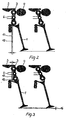
- FIGS 1, 2 and 3 show a first embodiment of a valve lift adjustment device according to the invention for a gas exchange valve in the form of an intake valve 1 of a cylinder of a combustion engine which is not shown in the drawing.
- a rocker lever 3 comprising three rollers, an external roller 9, a body area of the lever which can comprise a roller 10 and an internal roller 11. That rocker lever 3 is driven by a camshaft 4 via the external roller 9 and moves during one revolution of the camshaft 4 along a path 13.
- the path 13 is determined by the shape of the bearing 5 which is attached to or which is part of the engine, whereby the rocker lever 3 moves via the inner roller 11 over a bearing 7, which forms a part of the valve engagement means (a turning lever) 2.
- the rocker lever 3 moves around its body area 10, an area between the external roller 9 and the internal roller 11 and which can comprise a roller, around the positioning means 6.
- the body area of the lever 10 can also be in the form of a rigid contour of the lever.
- the positioning means 6 is positioned within a guide corresponding to a requested turning moment.
- the positioning means can take the positions 17 and 18 as shown in Figures 2 and 3.
- the position of the positioning means 6 determines the position of the pivot of the rocker lever 3 with respect to the vale engagement means and thus the area of the bearing 7 over which the roller 11 rolls.
- the bearing 7 is divided into areas, zero valve lift area 7a and valve lift area 7b ( Figure 1).
- the gas exchange valve 1 carries out only a partial valve lift.
- the rocker lever 3 is pushed by a spring 12 towards the camshaft 4 during valve lift movements of the valve.
- a further embodiment comprising the bearing 7 being divided into several curved areas which are linked to each other through transition radii.
- the path 13 along in which the rocker lever 3 moves via the roller 9 is determined by the shape of the bearing 5.
- the path 13 can have a circular, curved or semicircular surface or a plane surface.
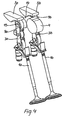
- two gas exchange valves 1a and 1b are operated by two rocker levers 3a and 3b being arranged on axis 15.
- the axis comprises, at its center between the rocker levers 3a and 3b, a common roller area 14 for the external rollers 9a and 9b which is either driven by the camshaft 4 ( Figure 4) or rolls over a bearing 5 that is attached to or is part of the engine. If the second roller area 14 rolls in the bearing 5, the first roller areas 9a and 9b are each driven by a cam 4. If the common second roller area 14 is driven by a cam of the camshaft 4, the two first roller areas 9a and 9b roll in two bearings 5a and 5b which are attached to or part of the engine. In another embodiment the three roller areas 9a, 9b, 14 are independent rollers and rest on a common axis 15.
- FIG. 1 A device for the valve lift adjustment of a gas exchange valve 1 of a not shown combustion engine is shown in Figure 1 wherein the gas exchange valve 1 is, for example, one of several intake or exhaust valves.
- the rocker lever 3 is driven by a cam shaft, moves around the positioning means and moves along a path which is determined by a bearing 5 that is attached to or part of the engine and 6.
- the position of the positioning means 6 determines the position of the pivot of the rocker lever and thus the area of the bearing 7 in which the roller 11 can roll.
- the bearing 7 is divided into two substantial areas; the zero valve lift area 7a and the valve lift area 7b ( Figure 1).
- valve 1 does not carry out a valve lift ( Figure 2). If the positioning means is brought into position 2, the roller 11 rolls during one revolution of the camshaft within the valve lift area 7b of the bearing 7 and the valve 1 carries out the maximum valve lift ( Figure 3). Between position 1 and 2 of the positioning means every position can be adjusted ( Figure 2, 3). In those intermediate positions the valve carries out partial valve lifts. The rocker lever is pushed by a biasing means 12 towards the camshaft.
- roller 9 Since the roller 9 should not roll on the camshaft 4 and over the bearing 5 in the same time two levers are usually arranged on an axis 15 (Figure 4).
- This axis 15 has at its center a roller 14 which rolls either over a bearing 5 that is attached to or part of the engine or is driven by the cam 4 ( Figure 4). If the roller 14 rolls in the bearing 5, the two external rollers 9a and 9b are each driven by a cam. If the roller 14 is driven by the cam 4, the two external rollers 9a and 9b roll in the two bearings 5a and 5b that are attached to or are part of the engine ( Figure 4).
- the rocker lever comprises an axis with three rollers where, for example, two rollers roll around the contour of the cam and the middle roller rolls over the bearing 5.
- the two external rollers roll over the bearing that is attached to or is part of the engine while the internal roller is driven by the cam of a camshaft.
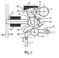
- Figure 5 shows a device for a valve lift adjustment of valves according to the invention in particular of a gas exchange valve 1 of a not shown combustion engine, wherein the gas exchange valve 1 is one of several similar intake valves of a cylinder.
- the rocker lever 3 is driven by the camshaft 4 and moves via the roller 9 along a path 13 which is determined by the bearing 5 that is attached to or is part of the engine.
- the rocker lever 3 moves via a second roller 10 around the contour 19 of the positioning means 6.
- the rocker lever 3 further comprises a working curve 20, which is in contact with the roller 21 of the valve engagement means 2, being here a roller lever.
- the positioning means 6 is positioned within a guide 22 for adjusting the valve lift.
- a zero valve lift is carried out if the positioning means is brought into position 17 while a maximum valve lift of the intake valve 1 is carried out if the positioning means 6 is in position 18.
- a preferred geometry is given if the curvature of bearing 5 is determined by a circular arc 23 around the center point of roller 21 and the area of the working curve 20 forms a circular arc 24 around the center point of the roller 9.
- the intake valve 1 is not opened during one revolution of the camshaft 4 if the positioning means 6 is in the zero valve lift position 17.
- the transition of the first area to the second area of the working curve 20 is limited by the radius of roller 21 and determines the shape of the ramp of the valve lifting curve during valve opening and closing.
- the second area of the working curve 20 defines the valve lift area.
- the shape of the working curve 20 determines the maximum valve lift and the valve acceleration of the partial valve lifts.
- the opening time of the valve lift is changed according to the invention dependent on the valve lift since the position of the positioning means 6 determines in which area of the working curve 20 the roller 21 rolls during one revolution of the cam shaft 4.
- Figure 6 shows that for example in a combustion engine having two intake valves, the rocker levers 3a and 3b can rest on a common axis 15 and the camshaft 4 can act on a roller located on the axis 15.
- the positioning means can take up different positions such that for one revolution of the camshaft 4 the intake valves have different valve opening times and have carried out different valve lifts.
- FIG. 7 A further embodiment of the invention shown in Figure 7 where the bearing 5 and the contour 19 of the positioning means 6 have plane surfaces aligned perpendicularly to each other or which comprise between them an angle of 90°.
- the rocker lever 3 is pushed by a spring 12 towards the positioning means 6 and the camshaft 4, in order to keep the system free of play and prevent lifting of the lever 3 from the camshaft 4 or the positioning means 6 during high revolutions.
- the spring 12 can also be composed of two or more springs.
Landscapes
- Engineering & Computer Science (AREA)
- Mechanical Engineering (AREA)
- General Engineering & Computer Science (AREA)
- Valve Device For Special Equipments (AREA)
- Valve-Gear Or Valve Arrangements (AREA)
- Braking Systems And Boosters (AREA)
Abstract
Description
- The invention relates to a device for adjusting the valve lift of valves in combustion engines and to a method for adjusting the valve lift of valves in combustion engines. Furthermore, the invention relates to combustion engines comprising a device for valve lift adjustment.
- Devices for adjusting the valve lift in combustion engines typically comprise a cam shaft driving a valve engagement means, this usually being a roller lever, which cooperates with the valve and moves the latter. More complex devices comprise additional levers being arranged between the valve engagement means and the camshaft. Those levers are typically turning levers, i.e. one-armed levers. An example for such a device is given in EP-A1-01 255 027 which describes a mechanically controllable valve lift adjustment for gas exchange valves of combustion engines wherein a turning lever is driven by a cam shaft and cooperates with a valve engagement means (that means being a roller lever). The turning lever is positioned by a positioning means and pushed back towards the camshaft by a spring. The turning lever also comprises an external roller which rolls over a bearing that is part of the engine.
- US 4 397 270 A discloses a device for adjusting the valve lift of valves of a combustion engine according to the preamble of claim 1 and a method according to the preamble of
claim 19. - It is an object of the present invention to provide a device for adjusting the valve lift of valves of combustion engines which has a lower moment of inertia compared to known devices for valve lift adjustment thus helping to improve the efficiency of combustion engines. It is also an object of the invention to provide a device for adjusting the valve lift that allows the realization of high revolutions and/or valve accelerations. Another object of the invention is to provide a device that enables a more fine-tuned and easily achieved adjustment of low valve lifts during the periods of idle strokes in combustion engines. A further object of the invention is to provide a device for the adjustment of the valve lift in combustion engines showing fewer signs of wear compared to other known devices.
- Provided by the invention is a device for stroke adjustments of valves of a combustion engine, the device comprising a lever driven by a cam shaft, said lever having at least two arms, wherein at least one arm moves on a bearing, said lever is pushed against the cam shaft by a biasing means and positioned by at least one positioning means and cooperates with a valve engagement means that cooperates with at least one valve of the combustion engine, characterized in that the lever comprises at least one roller which rolls over the bearing, wherein the lever is moved by the action of the cam shaft on the roller.
- Also provided by the invention is a combustion engine comprising a device as above.
- Additionally provided by the invention is a method for adjusting the valve lift of valves.
- The device and method according to the invention provide a controllable and variable, preferably mechanical, adjustment of the valve lift in a combustion engine. The present invention allows the lift of several valves be adjusted independently and variably. The valve lift can be increased or reduced depending on the engine performance (such as for example the revolution and/or the acceleration) required. Suitable combustion engines are engines for motor vehicles, ship or aircraft engines. The engines can be single- or multiple valve engines. The engines can also be single as well as multiple cylinder engines. Typically the valves to be adjusted are gas-exchanges valves, inlet or intake and/or outlet/exhaust valves.
- The device according to the invention is particularly suitable for revolutions of from more than 0 to up to 4000, preferably up to 6000 and more preferably up to 8.000 rpm (revolutions per minute).
- In the device according to the invention the lever is driven by a camshaft and cooperates with a valve engagement means, driving the same. The valve engagement means cooperates with the valve and moves the latter. By displacing the lever, i.e. varying the position of the pivot of the lever with respect to the valve engagement means the valve lift is adjusted. Displacement of the lever, i.e the positioning of the lever, is achieved by a positioning means.
- The device according to the invention comprises a lever having at least two arms. Each of the arms has at least one outer end. The part of the lever between the outer ends of the arms is referred to herein as the body area of the lever.
- Preferably, the lever is a rocker lever. A rocker lever is understood herein to mean a lever which turns around a pivot wherein the pivot is not located at or in proximity to the outer ends of the lever. Preferably the pivot of the rocker lever is situated in or substantially in proximity to the center of mass the lever.
- The lever has at least two arms, one of them comprising, preferably at the outer end, a means for bearing the lever, preferably rotatably, in a bearing. That means is preferably a roller but can for example also be a suitable shape or rigid contour of the lever allowing a rather frictionless movement of the lever on the bearing. The bearing is preferably attached to the engine or is a part of the engine.
- The shape of the bearing determines the path on which the lever moves. The shape of the bearing can be plane, curved or it can be of circular or semi-circular shape.
- The lever is driven by action of a camshaft or a means transmitting the driving force of a camshaft, preferably by cooperating with the means bearing the lever in the bearing. The lever may also comprise a means for cooperating with the camshaft. Such a means can for example be a suitable shape or rigid contour of the lever allowing a rather frictionless cooperation. The means can also be a roller. Preferably, the means cooperating with the camshaft are identical to the means bearing the lever in the bearing.
- The lever is pushed against the camshaft by a biasing means, which is preferably a spring.
- The lever acts on a valve engagement means, preferably by its other arm and preferably by the cooperation of one or more further roller with one or more working curve or further bearing. For this purpose the lever may comprise one or more further roller which cooperates with a working curve or a bearing located on the valve engagement means. The lever may also comprise a working curve or a further bearing with cooperates with a roller on the valve engagement means, which in this case is preferably a roller lever.
- In one embodiment of the invention the working curve is divided into curve areas, for example a zero valve lift area and a valve lift area, wherein the areas can be linked by transition curves or radii.
- The valve engagement means cooperates with at least one valve and moves the latter. Typical valve engagement means are roller levers or drag (turning) levers. It is an advantage of the invention that the device is not limited to one specific typ of valve engagement means, The valve engagement means can for example also be a pivoted rocker lever or a non-rotatable lever moved in a guide.
- A positioning means cooperates with the lever and positions the lever and the lever further comprises a means for cooperating with a positioning means displacing the lever.
- If the two-or more armed lever comprises at least two rollers, those rollers are preferably aligned along an axis of the lever.
- The lever can be made from materials providing a sufficient stiffness. Preferably light materials are used which contribute to reducing the inertia of the lever. Suitable materials are, for example, aluminum, titanium or alloys thereof, steal, steal mixtures, suitable plastics or composite materials. The bearings can be made of the same or different material to the engine and/or the lever.
- The lever is positioned by a positioning means for the adjustment of the valve lift. The positioning means act on the pivot of the lever and the lever moves around the positioning means. The positioning means is suitably formed and/or has a suitable contour to facilitate the movement of the lever around the positioning means. The lever comprises a means for cooperating with the positioning means.
- Such means may be a suitable shape or rigid contour or a roller, in order to facilitate the movement of the lever along the contour of the positioning means. Such a roller, shape or contour however should not be identical to the one on which the camshaft acts for moving the lever. The positioning means is for example a suitably shaped driven rail that can be brought in various positions, for example, by moving it forward or backward. Depending on the position the positioning means is brought into, the pivot of the lever is displaced with respect to the valve engagement means. The positioning means can be driven and positioned in any suitable manner known to the person skilled in the art, for example, mechanically, hydraulically, pneumatically, electrically, electromagnetically and/or piezoelectrically. The lever is displaced by action of the positioning means in accordance with the requirements as to the performance of the engine. Such requirements can be combustion valves, revolutions and/or turning moments. Preferably, the positioning means in accordance to a required torque.
- In one embodiment of the device to the cylinder of the engine comprises more than one valve, for example more than one intake valve per cylinder and each valve cooperates via a valve engagement means with the lever. The levers according to this embodiment may be arranged on a common axis and are positioned preferably by one positioning means per lever such that for each valve the valve lift can be controlled and adjusted individually. For example, for the individual valve lift adjustment of two gas exchange valves, for example two intake or exhaust valves respectively, or one intake and one exhaust valve an arrangement is provided wherein two rollers on two rocker levers are located on a common axis and wherein each of these rollers rolls in a separate bearing and the levers being displaced independently from each other depending on the position of the positioning means.
- The device according to the invention and the configuration of the lever allows in particular to achieve high revolutions. The working curve and the contour of the positioning means can be shaped such as to increase the maximum stroke acceleration of the intake or exhaust valve on reducing the valve lift. The device furthermore allows the opening time of the valves being reduced on reducing the valve lift.
- One embodiment of the invention is a device for the controllable variable adjustment of the valve lift of gas exchange valves in a combustion engine wherein additional rocker levers are moved in a divided bearing, driven by a cam shaft and positioned by a positioning means. A roller of the rocker lever rolls over a bearing that is attached to or is part of the engine and a second roller rolls over a bearing which is part of a valve engagement means. For adjusting the valve lift the positioning means are driven in a guide according to a required turning moment. The arrangement and the configuration of the rocker lever allows for achieving also high revolutions. By using a rocker lever having two rollers, the moment of inertia can be reduced compared to a turning lever comprising only one roll. Furthermore, the rocker lever can be made of aluminum contributing to a further reduction of the dynamic forces. The embodiment can also be used to adjust low valve lifts during idle stroke periods of a multiple cylinder combustion engine for minute variations for each cylinder since one part of the bearing is a part or an integral part of the valve engagement means.
- A further embodiment of the invention is a device for the mechanical adjustment of the valve lift wherein a rocker lever is driven by a cam shaft and biased by a spring and moves with a first roller over a bearing and with a second roller over the contour of an adjustable rail (positioning means) that cooperates with a valve engagement means being a roller lever. The bearing over which the lever moves and the contour of the positioning means may comprise plane surfaces which are, in a preferred embodiment, aligned perpendicularly to each other. A feature of this embodiment is that the opening period of the valve can be reduced by reduction of the valve lift. Preferably, the bearing is curved and the curvature of the bearing is determined by the circular arc around the center point of the roller of the roller lever with which the rocker lever cooperates. The rocker lever comprises a working curve which cooperates with the roller of the roller lever (the valve engagement means). The working curve has a first area and that first area has the curvature of a circular arc around the center point of the first roller.
- The working curve and the contour of the positioning means are preferably arranged such that the acceleration of the intake or exhaust valves, respectively, increases with reducing valve lift.
- The invention is described in the following by examples. Hereby shows:
- Fig. 1
- a first embodiment of a device for adjusting the valve lift according to the invention for one intake valve;
- Fig. 2
- the first embodiment for the intake valve at zero valve lift position;
- Fig. 3
- the first embodiment for the intake valve in valve lift position;
- Fig. 4
- a second embodiment of the device for valve lift adjustment of the invention for two intake valves;
- Fig. 5
- a third embodiment of the device for valve lift adjustment according to the invention;
- Fig. 6
- an embodiment with two valves in three different views
- Fig. 7
- a fourth embodiment having a plane contour and a plane bearing surface.
- The Figures 1, 2 and 3 show a first embodiment of a valve lift adjustment device according to the invention for a gas exchange valve in the form of an intake valve 1 of a cylinder of a combustion engine which is not shown in the drawing. A
rocker lever 3 comprising three rollers, anexternal roller 9, a body area of the lever which can comprise aroller 10 and aninternal roller 11. Thatrocker lever 3 is driven by acamshaft 4 via theexternal roller 9 and moves during one revolution of thecamshaft 4 along apath 13. Thepath 13 is determined by the shape of thebearing 5 which is attached to or which is part of the engine, whereby therocker lever 3 moves via theinner roller 11 over a bearing 7, which forms a part of the valve engagement means (a turning lever) 2. Therocker lever 3 moves around itsbody area 10, an area between theexternal roller 9 and theinternal roller 11 and which can comprise a roller, around the positioning means 6. The body area of thelever 10 can also be in the form of a rigid contour of the lever. For the adjustment of a valve lift 16 (Figure 3) the positioning means 6 is positioned within a guide corresponding to a requested turning moment. The positioning means can take thepositions rocker lever 3 with respect to the vale engagement means and thus the area of the bearing 7 over which theroller 11 rolls. The bearing 7 is divided into areas, zero valve lift area 7a and valve lift area 7b (Figure 1). These two areas are linked via transition radii or connection curves or by connecting planes, respectively. The radius of the curvature of the transition surface must be greater than the radius of therole 11 and determines the height of the acceleration ramp. If theroller 11 rolls during one revolution of thecamshaft 4 only within the zero stroke area 7a, due topositions 17 of the positioning mean 6, the gas exchange valve 1 does not carry out a valve lift (Figure 2). If the positioning means 6 is positioned to take theposition 18, theroller 11 rolls during one revolution of thecam shaft 4 over the stroke area 7b of the bearing 7 and the gas exchange valve 1 carries out themaximum valve lift 16. Betweenpositions rocker lever 3 is pushed by aspring 12 towards thecamshaft 4 during valve lift movements of the valve. A further embodiment comprising the bearing 7 being divided into several curved areas which are linked to each other through transition radii. Thepath 13 along in which therocker lever 3 moves via theroller 9 is determined by the shape of thebearing 5. For example, thepath 13 can have a circular, curved or semicircular surface or a plane surface. - In the second embodiment according to Figure 4 two gas exchange valves 1a and 1b are operated by two
rocker levers axis 15. The axis comprises, at its center between the rocker levers 3a and 3b, acommon roller area 14 for theexternal rollers bearing 5 that is attached to or is part of the engine. If thesecond roller area 14 rolls in thebearing 5, thefirst roller areas cam 4. If the commonsecond roller area 14 is driven by a cam of thecamshaft 4, the twofirst roller areas roller areas common axis 15. - A device for the valve lift adjustment of a gas exchange valve 1 of a not shown combustion engine is shown in Figure 1 wherein the gas exchange valve 1 is, for example, one of several intake or exhaust valves. In this device the
rocker lever 3 is driven by a cam shaft, moves around the positioning means and moves along a path which is determined by abearing 5 that is attached to or part of the engine and 6. The position of the positioning means 6 determines the position of the pivot of the rocker lever and thus the area of the bearing 7 in which theroller 11 can roll. The bearing 7 is divided into two substantial areas; the zero valve lift area 7a and the valve lift area 7b (Figure 1). If theroller 11 rolls during one revolution of the cam shaft only over the zero valve lift area 7a, due to the position of the positioning means, the valve 1 does not carry out a valve lift (Figure 2). If the positioning means is brought intoposition 2, theroller 11 rolls during one revolution of the camshaft within the valve lift area 7b of the bearing 7 and the valve 1 carries out the maximum valve lift (Figure 3). Betweenposition 1 and 2 of the positioning means every position can be adjusted (Figure 2, 3). In those intermediate positions the valve carries out partial valve lifts. The rocker lever is pushed by a biasing means 12 towards the camshaft. - Since the
roller 9 should not roll on thecamshaft 4 and over thebearing 5 in the same time two levers are usually arranged on an axis 15 (Figure 4). Thisaxis 15 has at its center aroller 14 which rolls either over abearing 5 that is attached to or part of the engine or is driven by the cam 4 (Figure 4). If theroller 14 rolls in thebearing 5, the twoexternal rollers roller 14 is driven by thecam 4, the twoexternal rollers bearing 5. In another suitable arrangement, the two external rollers roll over the bearing that is attached to or is part of the engine while the internal roller is driven by the cam of a camshaft. - Figure 5 shows a device for a valve lift adjustment of valves according to the invention in particular of a gas exchange valve 1 of a not shown combustion engine, wherein the gas exchange valve 1 is one of several similar intake valves of a cylinder. In this device the
rocker lever 3 is driven by thecamshaft 4 and moves via theroller 9 along apath 13 which is determined by thebearing 5 that is attached to or is part of the engine. Therocker lever 3 moves via asecond roller 10 around thecontour 19 of the positioning means 6. Therocker lever 3 further comprises a workingcurve 20, which is in contact with theroller 21 of the valve engagement means 2, being here a roller lever. The positioning means 6 is positioned within aguide 22 for adjusting the valve lift. For example, a zero valve lift is carried out if the positioning means is brought intoposition 17 while a maximum valve lift of the intake valve 1 is carried out if the positioning means 6 is inposition 18. A preferred geometry is given if the curvature ofbearing 5 is determined by acircular arc 23 around the center point ofroller 21 and the area of the workingcurve 20 forms acircular arc 24 around the center point of theroller 9. At this configuration the intake valve 1 is not opened during one revolution of thecamshaft 4 if the positioning means 6 is in the zerovalve lift position 17. The transition of the first area to the second area of the workingcurve 20 is limited by the radius ofroller 21 and determines the shape of the ramp of the valve lifting curve during valve opening and closing. The second area of the workingcurve 20 defines the valve lift area. The shape of the workingcurve 20 determines the maximum valve lift and the valve acceleration of the partial valve lifts. The opening time of the valve lift is changed according to the invention dependent on the valve lift since the position of the positioning means 6 determines in which area of the workingcurve 20 theroller 21 rolls during one revolution of thecam shaft 4. - Figure 6 shows that for example in a combustion engine having two intake valves, the rocker levers 3a and 3b can rest on a
common axis 15 and thecamshaft 4 can act on a roller located on theaxis 15. The positioning means can take up different positions such that for one revolution of thecamshaft 4 the intake valves have different valve opening times and have carried out different valve lifts. - A further embodiment of the invention shown in Figure 7 where the
bearing 5 and thecontour 19 of the positioning means 6 have plane surfaces aligned perpendicularly to each other or which comprise between them an angle of 90°. Therocker lever 3 is pushed by aspring 12 towards the positioning means 6 and thecamshaft 4, in order to keep the system free of play and prevent lifting of thelever 3 from thecamshaft 4 or the positioning means 6 during high revolutions. Thespring 12 can also be composed of two or more springs. -
- 1
- gas exchange valve
- 1a
- gas exchange valve
- 1b
- gas exchange valve
- 2
- drag lever (turning lever)
- 3
- rocker lever
- 3a
- rocker lever
- 3b
- rocker lever
- 4
- camshaft
- 5
- bearing attached to or part of the engine
- 5a
- bearing attached to or part of the engine
- 5b
- bearing attached to or part of the engine
- 6
- positioning means
- 7
- bearing
- 7a
- zero valve lift area of the bearing
- 7b
- valve lift area of the bearing
- 8
- bolt
- 9
- external roller
- 9a
- external roller
- 9b
- external roller
- 10
- roller (body area, rigid contour)
- 11
- inner roller
- 12
- spring
- 13
- path
- 14
- common second roller area
- 15
- axis
- 16
- valve lift
- 17
- position 1 of the positioning means
- 18
-
position 2 of the positioning means - 19
- contour
- 20
- working curve
- 21
- roller
- 22
- guide
- 23
- circular arc
- 24
- circular arc
Claims (26)
- A device for adjusting the valve lift of valves (1) of a combustion engine, the device comprising a lever (3) driven by a cam shaft (4), said lever having at least two arms, wherein at least one arm moves on a bearing (5), said lever (3) is pushed against the cam shaft (4) by a biasing means (12) and positioned by at least one positioning means (6) and cooperates with a valve engagement means (2) that cooperates with at least one valve of the combustion engine,
characterized in
that the lever (3) comprises at least one roller (9) which rolls over the bearing (5), wherein the lever (3) is moved by the action of the cam shaft (4) on the roller (9). - A device according to claim 1 wherein the lever (3) is a rocker lever.
- A device according to any one of the preceding claims wherein the bearing (5) is attachable to or is adapted to be a part of the engine.
- A device according to any one of the preceding claims, wherein the lever (3) moves around the positioning means (6).
- A device according to any one of the preceding claims, wherein the lever (3) comprises a further roller (11) which rolls over a further bearing (7), wherein said bearing is adapted to be a part of the valve engaging means (2).
- A device according to any one of the preceding claims, wherein the lever (3) comprises a roller (10) which cooperates with the positioning means (6) and wherein the lever (3) moves around the positioning means (6) via said roller (10).
- A device according to any one of claims 1 to 5, wherein the positioning means (6) cooperates with a rigid contour (10) of the lever (3) and wherein the lever (3) moves around the positioning means (6) via said rigid contour (10).
- A device according to any one of the preceding claims, wherein the device comprises at least two levers (3a, 3b), each of which comprising a first roller (9a, 9b) each rolling in a bearing (5a, 5b), whereby said levers (3a, 3b) are positioned by the positioning means cooperating with the pivots of the levers (3a, 3b), wherein each of the levers (3a, 3b) acts on the valve engaging means by cooperation of a second roller with a working curve, and wherein the first rollers (9a, 9b) of the levers (3a, 3b) rest on an axis (15) and are driven by the cam shaft (4), and wherein the levers (3a, 3b) can be positioned independently to each other by the positioning means.
- A device according to claim 8, wherein the two first rollers (9a, 9b) comprise a first roller area, being located at one end of the levers (3a, 3b) and a second common roller area (14) being located between the levers (3a, 3b) on the common axis (15).
- A device according to either one of claim 8 or 9, wherein the levers (3a, 3b) are driven by a common cam of the cam shaft (4), said common cam cooperating with the common second roller area (14).
- A device according to any one of claims 8 to 10, wherein the common second roller area (14) cooperates with the path (13) defined by the bearings (5a, 5b) said bearings being attachable to or being adapted to be a part of the engine, and wherein the two first roller areas (9a, 9b) cooperate with the cam shaft (4).
- A device according to any one of claims 1 to 4, wherein the lever (3) comprises a further roller (10) which moves around the positioning means (6) and wherein the lever (3) comprises a working curve (20) that cooperates with the valve engagement means (2).
- A device according to claim 12, wherein the valve engagement means (2) is a roller lever, with whose roller (21) the lever (3) cooperates via its working curve (20).
- A device according to claim 13, wherein the path (13) defined by the bearing (5) is curved and the curvature is determined by a circular arc around the center point of the roller (21) of the roller lever (2).
- A device according to claim 14, wherein the bearing (5) and a contour (19) of the positioning means (6) comprises plane surfaces.
- A device according to claim 15, wherein the plane surfaces of the bearing (5) and the contour (19) are aligned perpendicularly to each other.
- A device according to any one of claims 12 to 16 for adjusting the valve lift of at least two valves, wherein the device comprises at least two levers (3a, 3b) according to claim 14, which rest on a common axis (15) and which can be positioned by a positioning means such that the valves can carry out strokes which differ from each other.
- A combustion engine comprising a device according to any one of the preceding claims.
- A method for adjusting the valve lift of valves (1) whereas for the adjustment of the valve lift, rocker levers (3, 3a, 3b) are operated, which are positioned by positioning means (6), and which are driven in a path (13) by a cam shaft (4),
characterized in
that the rocker lever (3, 3a, 3b) rolls with a roller (9, 9a, 9b) over the path (13) and at the same time moves via a roller (10) pivoted at the lever, or instead of the roller (10), via a rigid contour of the lever around the contour of the positioning means (6). - Method according to claim 19, characterized in that a further roller (11) rolls over a further bearing (7).
- A method according to any one of claims 19 or 20, characterized in that by carrying out a variable valve lift adjustment for two valves (1a, 1b), two external rollers (9a, 9b) of two levers (3a, 3b), being linked via a common axis (15) and having a common roller (14), roll in two bearings (5a, 5b) and wherein the common roller (14) is driven by a cam of the cam shaft (4).
- A method according to claim 21, characterized in that the common roller (14) rolls in a bearing (5) and the external rollers (9a, 9b) are driven by the cam shaft (4).
- A method according to any one of claims 19 to 22, wherein with an arrangement of two rocker levers (3a, 3b) provided on a common axis (15), the strokes of the valves can be adjusted differently from each other.
- A method according to any one of claims 19 to 23, characterized in that for the adjustment of the valve lift, the positioning means (6) is positioned in a guidance corresponding to a desired torsional moment.
- A method according to any one of claims 20 to 24, characterized in that by way of the positioning the positioning means (6) a pivot of the rocker lever (3) and the area of the bearing (7) in which the roller (11) rolls is determined.
- A method according to any one of claims 22 to 25, characterized in that the rocker lever (3) moves during one revolution of the cam shaft (4) along a path that is determined by the bearing (5).
Applications Claiming Priority (3)
| Application Number | Priority Date | Filing Date | Title |
|---|---|---|---|
| DE10228022A DE10228022B4 (en) | 2002-06-20 | 2002-06-20 | Valve lifting device for stroke adjustment of the gas exchange valves of an internal combustion engine |
| DE10228022 | 2002-06-20 | ||
| PCT/EP2003/006550 WO2004001198A1 (en) | 2002-06-20 | 2003-06-20 | A stroke adjusting device for valves of a combustion engine |
Publications (2)
| Publication Number | Publication Date |
|---|---|
| EP1520088A1 EP1520088A1 (en) | 2005-04-06 |
| EP1520088B1 true EP1520088B1 (en) | 2006-09-13 |
Family
ID=29723392
Family Applications (1)
| Application Number | Title | Priority Date | Filing Date |
|---|---|---|---|
| EP03735658A Expired - Lifetime EP1520088B1 (en) | 2002-06-20 | 2003-06-20 | A stroke adjusting device for valves of a combustion engine |
Country Status (10)
| Country | Link |
|---|---|
| US (2) | US7418935B2 (en) |
| EP (1) | EP1520088B1 (en) |
| JP (1) | JP4366314B2 (en) |
| KR (1) | KR100949524B1 (en) |
| CN (1) | CN100368659C (en) |
| AT (1) | ATE339597T1 (en) |
| AU (1) | AU2003237968A1 (en) |
| DE (2) | DE10228022B4 (en) |
| TW (1) | TWI279483B (en) |
| WO (1) | WO2004001198A1 (en) |
Families Citing this family (21)
| Publication number | Priority date | Publication date | Assignee | Title |
|---|---|---|---|---|
| DE10228022B4 (en) * | 2002-06-20 | 2009-04-23 | Entec Consulting Gmbh | Valve lifting device for stroke adjustment of the gas exchange valves of an internal combustion engine |
| US6978751B2 (en) * | 2002-07-18 | 2005-12-27 | Kohler Co. | Cam follower arm for an internal combustion engine |
| DE102004013767B4 (en) * | 2004-03-20 | 2008-06-19 | Audi Ag | Method for diagnosing the functionality of a valve lift adjustment of an internal combustion engine |
| JP4342372B2 (en) * | 2004-04-28 | 2009-10-14 | 本田技研工業株式会社 | Valve operating device for internal combustion engine |
| DE102006018512A1 (en) * | 2006-04-21 | 2007-10-25 | Schaeffler Kg | Roller element for a pivotable machine part |
| JP4896817B2 (en) * | 2006-07-25 | 2012-03-14 | 本田技研工業株式会社 | Variable valve operating device for internal combustion engine |
| CN101225759B (en) * | 2008-01-25 | 2010-06-09 | 许小法 | Variable spiracula lifting device |
| EP2157292A1 (en) * | 2008-08-20 | 2010-02-24 | Delphi Technologies, Inc. | Valve gear assembly for an internal combustion engine |
| CN102762841B (en) * | 2009-11-05 | 2016-03-30 | 丰田自动车株式会社 | engine air intake |
| JP2011208631A (en) * | 2010-03-12 | 2011-10-20 | Nsk Ltd | Tappet roller bearing |
| CN101858233B (en) * | 2010-04-29 | 2016-04-20 | 朱譞晟 | Comprise full Variable Valve Time method and the mechanism of speed-changing swing mechanism |
| DE102010048708A1 (en) * | 2010-10-19 | 2012-04-19 | Kolbenschmidt Pierburg Innovations Gmbh | Mechanically controllable valve train |
| CN102155273A (en) * | 2011-04-08 | 2011-08-17 | 奇瑞汽车股份有限公司 | Variable gas distribution mechanism of engine |
| DE102011082227A1 (en) * | 2011-09-07 | 2013-03-07 | Bayerische Motoren Werke Aktiengesellschaft | Setting for a variable stroke valve train in a cylinder head of an internal combustion engine |
| DE102012001633A1 (en) * | 2012-01-30 | 2013-08-01 | Kolbenschmidt Pierburg Innovations Gmbh | Mechanically controllable valve train arrangement |
| US9217382B2 (en) | 2012-03-13 | 2015-12-22 | Ford Global Technologies, Llc | Method and system for engine air control |
| CN103742219B (en) * | 2013-12-30 | 2016-05-11 | 长城汽车股份有限公司 | For the valve actuating mechanism of engine and there is its vehicle |
| CN103742221B (en) * | 2013-12-30 | 2016-03-30 | 长城汽车股份有限公司 | For motor distribution device and there is its vehicle |
| DE102014100748B4 (en) * | 2014-01-23 | 2017-04-27 | Pierburg Gmbh | Transmission arrangement for a mechanically controllable valve train and mechanically controllable valve train |
| WO2017214708A1 (en) * | 2016-06-17 | 2017-12-21 | Antonio Cannata | Wedge arm based device providing variable operation of a device |
| CN106761993B (en) * | 2016-12-02 | 2018-12-28 | 肖光宇 | Reciprocating piston internal combustion engine starts cylinder exhaust valve opening mechanism |
Family Cites Families (12)
| Publication number | Priority date | Publication date | Assignee | Title |
|---|---|---|---|---|
| JPS55137305A (en) * | 1979-04-13 | 1980-10-27 | Nissan Motor Co Ltd | Valve lift for internal combustion engine |
| EP0638706A1 (en) * | 1993-08-05 | 1995-02-15 | Bayerische Motoren Werke Aktiengesellschaft | Valve actuating mechanism of an internal combustion engine |
| DE19509604A1 (en) | 1995-03-16 | 1996-09-19 | Bayerische Motoren Werke Ag | Valve train of an internal combustion engine |
| DE19548389A1 (en) | 1995-12-22 | 1997-06-26 | Siemens Ag | Adjustment device for the stroke of a gas exchange valve of an internal combustion engine |
| EP1096115B1 (en) * | 1999-10-29 | 2002-07-10 | STS System Technology Services GmbH | Mechanically controlled intake valve lift in an internal combustion engine |
| ATE220444T1 (en) | 1999-10-29 | 2002-07-15 | Sts System Technology Services | MECHANICAL CONTROL OF THE STROKE ADJUSTMENT OF THE INLET VALVE OF AN INTERNAL COMBUSTION ENGINE |
| DE10100173A1 (en) * | 2001-01-04 | 2002-07-11 | Fev Motorentech Gmbh | Fully variable mechanical valve train for a piston internal combustion engine |
| ATE272787T1 (en) * | 2001-05-03 | 2004-08-15 | Sts System Technology Services | MECHANICAL CONTROL OF THE STROKE ADJUSTMENT OF THE INLET VALVE OF AN INTERNAL COMBUSTION ENGINE |
| DE10164493B4 (en) | 2001-12-29 | 2010-04-08 | Fraunhofer-Gesellschaft zur Förderung der angewandten Forschung e.V. | Device for the variable actuation of the charge exchange valves in reciprocating engines |
| DE10228022B4 (en) * | 2002-06-20 | 2009-04-23 | Entec Consulting Gmbh | Valve lifting device for stroke adjustment of the gas exchange valves of an internal combustion engine |
| DE10235401A1 (en) | 2002-08-02 | 2004-02-12 | Bayerische Motoren Werke Ag | Lift stroke-variable valve gear for cylinder head of internal combustion engine has second pivoting lever installed stationary on first lever to form one-piece and material uniform double lever arrangement |
| DE10261304B4 (en) * | 2002-12-27 | 2009-01-22 | BÖSL-FLIERL, Gerlinde | Valve lift device for variable valve control of the gas exchange valves of an internal combustion engine |
-
2002
- 2002-06-20 DE DE10228022A patent/DE10228022B4/en not_active Expired - Fee Related
-
2003
- 2003-06-20 EP EP03735658A patent/EP1520088B1/en not_active Expired - Lifetime
- 2003-06-20 AT AT03735658T patent/ATE339597T1/en active
- 2003-06-20 TW TW092116821A patent/TWI279483B/en not_active IP Right Cessation
- 2003-06-20 CN CNB038133784A patent/CN100368659C/en not_active Expired - Fee Related
- 2003-06-20 DE DE60308377T patent/DE60308377T2/en not_active Expired - Lifetime
- 2003-06-20 KR KR1020047019965A patent/KR100949524B1/en not_active Expired - Fee Related
- 2003-06-20 US US10/518,739 patent/US7418935B2/en not_active Expired - Fee Related
- 2003-06-20 WO PCT/EP2003/006550 patent/WO2004001198A1/en not_active Ceased
- 2003-06-20 AU AU2003237968A patent/AU2003237968A1/en not_active Abandoned
- 2003-06-20 JP JP2004514827A patent/JP4366314B2/en not_active Expired - Fee Related
-
2008
- 2008-08-14 US US12/191,354 patent/US7814875B2/en not_active Expired - Fee Related
Also Published As
| Publication number | Publication date |
|---|---|
| JP2005530092A (en) | 2005-10-06 |
| JP4366314B2 (en) | 2009-11-18 |
| CN100368659C (en) | 2008-02-13 |
| AU2003237968A1 (en) | 2004-01-06 |
| EP1520088A1 (en) | 2005-04-06 |
| DE10228022B4 (en) | 2009-04-23 |
| DE10228022A1 (en) | 2004-01-15 |
| KR20050020829A (en) | 2005-03-04 |
| TWI279483B (en) | 2007-04-21 |
| US7418935B2 (en) | 2008-09-02 |
| US20080295788A1 (en) | 2008-12-04 |
| ATE339597T1 (en) | 2006-10-15 |
| US7814875B2 (en) | 2010-10-19 |
| US20060201459A1 (en) | 2006-09-14 |
| TW200409856A (en) | 2004-06-16 |
| DE60308377D1 (en) | 2006-10-26 |
| CN1659364A (en) | 2005-08-24 |
| KR100949524B1 (en) | 2010-03-25 |
| WO2004001198A1 (en) | 2003-12-31 |
| DE60308377T2 (en) | 2007-09-06 |
Similar Documents
| Publication | Publication Date | Title |
|---|---|---|
| US7814875B2 (en) | Stroke adjusting device for valves of a combustion engine | |
| US5592906A (en) | Method and device for variable valve control of an internal combustion engine | |
| US7624711B2 (en) | Variable mechanical valve control for an internal combustion engine | |
| US7469669B2 (en) | Variable valve train mechanism of internal combustion engine | |
| US4364341A (en) | Valve control device for an internal combustion engine | |
| US6997153B2 (en) | Device for variably actuating the gas exchange valves in reciprocating engines | |
| US7069890B2 (en) | Valve train device for an engine | |
| US7096835B2 (en) | Valve train device for an engine | |
| JP4417260B2 (en) | Valve lift device for variable valve control of gas exchange valve of internal combustion engine | |
| US6955146B2 (en) | System for variably actuating valves in internal combustion engines | |
| US8201531B2 (en) | Desmodromic variable valve actuation | |
| US7225773B2 (en) | Variable stroke valve drive for an internal combustion engine | |
| EP1697619B1 (en) | Variable valve gear | |
| US6736095B2 (en) | Extended duration cam lobe for variable valve actuation mechanism | |
| WO2006124839A2 (en) | Variable overhead valve control for engines | |
| JP2004521245A (en) | Variable valve mechanism | |
| EP2198129A2 (en) | Desmodromic variable valve actuation | |
| GB2214570A (en) | Variable lift i.c. engine valves | |
| JPH02221612A (en) | Variable valve system of internal combustion engine | |
| US20060130786A1 (en) | Device for actuating the gas exchange valves in reciprocating engines | |
| JPH06159025A (en) | Variable valve operating system of engine | |
| JP2005291011A (en) | Variable valve gear for engine | |
| HUP0402684A2 (en) | Device for changing of valve lift for internal combustion engine |
Legal Events
| Date | Code | Title | Description |
|---|---|---|---|
| PUAI | Public reference made under article 153(3) epc to a published international application that has entered the european phase |
Free format text: ORIGINAL CODE: 0009012 |
|
| 17P | Request for examination filed |
Effective date: 20050120 |
|
| AK | Designated contracting states |
Kind code of ref document: A1 Designated state(s): AT BE BG CH CY CZ DE DK EE ES FI FR GB GR HU IE IT LI LU MC NL PT RO SE SI SK TR |
|
| AX | Request for extension of the european patent |
Extension state: AL LT LV MK |
|
| 17Q | First examination report despatched |
Effective date: 20050406 |
|
| DAX | Request for extension of the european patent (deleted) | ||
| GRAP | Despatch of communication of intention to grant a patent |
Free format text: ORIGINAL CODE: EPIDOSNIGR1 |
|
| RAP1 | Party data changed (applicant data changed or rights of an application transferred) |
Owner name: FLIERL, RUDOLF |
|
| RIN1 | Information on inventor provided before grant (corrected) |
Inventor name: MOHR, MARK, ANDY Inventor name: GOLLASCH, DANIEL Inventor name: FLIERL, RUDOLF |
|
| GRAS | Grant fee paid |
Free format text: ORIGINAL CODE: EPIDOSNIGR3 |
|
| GRAA | (expected) grant |
Free format text: ORIGINAL CODE: 0009210 |
|
| RAP1 | Party data changed (applicant data changed or rights of an application transferred) |
Owner name: HYDRAULIK-RING GMBH Owner name: ENTEC CONSULTING GMBH |
|
| AK | Designated contracting states |
Kind code of ref document: B1 Designated state(s): AT BE BG CH CY CZ DE DK EE ES FI FR GB GR HU IE IT LI LU MC NL PT RO SE SI SK TR |
|
| PG25 | Lapsed in a contracting state [announced via postgrant information from national office to epo] |
Ref country code: IT Free format text: LAPSE BECAUSE OF FAILURE TO SUBMIT A TRANSLATION OF THE DESCRIPTION OR TO PAY THE FEE WITHIN THE PRESCRIBED TIME-LIMIT;WARNING: LAPSES OF ITALIAN PATENTS WITH EFFECTIVE DATE BEFORE 2007 MAY HAVE OCCURRED AT ANY TIME BEFORE 2007. THE CORRECT EFFECTIVE DATE MAY BE DIFFERENT FROM THE ONE RECORDED. Effective date: 20060913 Ref country code: LI Free format text: LAPSE BECAUSE OF FAILURE TO SUBMIT A TRANSLATION OF THE DESCRIPTION OR TO PAY THE FEE WITHIN THE PRESCRIBED TIME-LIMIT Effective date: 20060913 Ref country code: FI Free format text: LAPSE BECAUSE OF FAILURE TO SUBMIT A TRANSLATION OF THE DESCRIPTION OR TO PAY THE FEE WITHIN THE PRESCRIBED TIME-LIMIT Effective date: 20060913 Ref country code: CH Free format text: LAPSE BECAUSE OF FAILURE TO SUBMIT A TRANSLATION OF THE DESCRIPTION OR TO PAY THE FEE WITHIN THE PRESCRIBED TIME-LIMIT Effective date: 20060913 Ref country code: NL Free format text: LAPSE BECAUSE OF FAILURE TO SUBMIT A TRANSLATION OF THE DESCRIPTION OR TO PAY THE FEE WITHIN THE PRESCRIBED TIME-LIMIT Effective date: 20060913 Ref country code: BE Free format text: LAPSE BECAUSE OF FAILURE TO SUBMIT A TRANSLATION OF THE DESCRIPTION OR TO PAY THE FEE WITHIN THE PRESCRIBED TIME-LIMIT Effective date: 20060913 Ref country code: SI Free format text: LAPSE BECAUSE OF FAILURE TO SUBMIT A TRANSLATION OF THE DESCRIPTION OR TO PAY THE FEE WITHIN THE PRESCRIBED TIME-LIMIT Effective date: 20060913 Ref country code: RO Free format text: LAPSE BECAUSE OF FAILURE TO SUBMIT A TRANSLATION OF THE DESCRIPTION OR TO PAY THE FEE WITHIN THE PRESCRIBED TIME-LIMIT Effective date: 20060913 |
|
| REG | Reference to a national code |
Ref country code: GB Ref legal event code: FG4D |
|
| REG | Reference to a national code |
Ref country code: CH Ref legal event code: EP |
|
| REG | Reference to a national code |
Ref country code: IE Ref legal event code: FG4D |
|
| REF | Corresponds to: |
Ref document number: 60308377 Country of ref document: DE Date of ref document: 20061026 Kind code of ref document: P |
|
| REG | Reference to a national code |
Ref country code: SE Ref legal event code: TRGR |
|
| PG25 | Lapsed in a contracting state [announced via postgrant information from national office to epo] |
Ref country code: BG Free format text: LAPSE BECAUSE OF FAILURE TO SUBMIT A TRANSLATION OF THE DESCRIPTION OR TO PAY THE FEE WITHIN THE PRESCRIBED TIME-LIMIT Effective date: 20061213 Ref country code: DK Free format text: LAPSE BECAUSE OF FAILURE TO SUBMIT A TRANSLATION OF THE DESCRIPTION OR TO PAY THE FEE WITHIN THE PRESCRIBED TIME-LIMIT Effective date: 20061213 |
|
| PG25 | Lapsed in a contracting state [announced via postgrant information from national office to epo] |
Ref country code: ES Free format text: LAPSE BECAUSE OF FAILURE TO SUBMIT A TRANSLATION OF THE DESCRIPTION OR TO PAY THE FEE WITHIN THE PRESCRIBED TIME-LIMIT Effective date: 20061224 |
|
| PG25 | Lapsed in a contracting state [announced via postgrant information from national office to epo] |
Ref country code: PT Free format text: LAPSE BECAUSE OF FAILURE TO SUBMIT A TRANSLATION OF THE DESCRIPTION OR TO PAY THE FEE WITHIN THE PRESCRIBED TIME-LIMIT Effective date: 20070226 |
|
| NLV1 | Nl: lapsed or annulled due to failure to fulfill the requirements of art. 29p and 29m of the patents act | ||
| ET | Fr: translation filed | ||
| REG | Reference to a national code |
Ref country code: CH Ref legal event code: PL |
|
| REG | Reference to a national code |
Ref country code: HU Ref legal event code: AG4A Ref document number: E001218 Country of ref document: HU |
|
| PLBE | No opposition filed within time limit |
Free format text: ORIGINAL CODE: 0009261 |
|
| STAA | Information on the status of an ep patent application or granted ep patent |
Free format text: STATUS: NO OPPOSITION FILED WITHIN TIME LIMIT |
|
| 26N | No opposition filed |
Effective date: 20070614 |
|
| PG25 | Lapsed in a contracting state [announced via postgrant information from national office to epo] |
Ref country code: MC Free format text: LAPSE BECAUSE OF NON-PAYMENT OF DUE FEES Effective date: 20070630 |
|
| PG25 | Lapsed in a contracting state [announced via postgrant information from national office to epo] |
Ref country code: GR Free format text: LAPSE BECAUSE OF FAILURE TO SUBMIT A TRANSLATION OF THE DESCRIPTION OR TO PAY THE FEE WITHIN THE PRESCRIBED TIME-LIMIT Effective date: 20061214 |
|
| PG25 | Lapsed in a contracting state [announced via postgrant information from national office to epo] |
Ref country code: IE Free format text: LAPSE BECAUSE OF NON-PAYMENT OF DUE FEES Effective date: 20070620 |
|
| PG25 | Lapsed in a contracting state [announced via postgrant information from national office to epo] |
Ref country code: EE Free format text: LAPSE BECAUSE OF FAILURE TO SUBMIT A TRANSLATION OF THE DESCRIPTION OR TO PAY THE FEE WITHIN THE PRESCRIBED TIME-LIMIT Effective date: 20060913 |
|
| PG25 | Lapsed in a contracting state [announced via postgrant information from national office to epo] |
Ref country code: CY Free format text: LAPSE BECAUSE OF FAILURE TO SUBMIT A TRANSLATION OF THE DESCRIPTION OR TO PAY THE FEE WITHIN THE PRESCRIBED TIME-LIMIT Effective date: 20060913 Ref country code: LU Free format text: LAPSE BECAUSE OF NON-PAYMENT OF DUE FEES Effective date: 20070620 |
|
| PG25 | Lapsed in a contracting state [announced via postgrant information from national office to epo] |
Ref country code: TR Free format text: LAPSE BECAUSE OF FAILURE TO SUBMIT A TRANSLATION OF THE DESCRIPTION OR TO PAY THE FEE WITHIN THE PRESCRIBED TIME-LIMIT Effective date: 20060913 |
|
| REG | Reference to a national code |
Ref country code: GB Ref legal event code: 732E Free format text: REGISTERED BETWEEN 20100218 AND 20100224 |
|
| REG | Reference to a national code |
Ref country code: FR Ref legal event code: TP |
|
| REG | Reference to a national code |
Ref country code: SK Ref legal event code: PC4A Ref document number: E 1288 Country of ref document: SK Owner name: ENTEC CONSULTING GMBH, HEMER, DE Free format text: FORMER OWNER: HYDRAULIK-RING GMBH, MARKTHEIDENFELD, DE; ENTEC CONSULTING GMBH, HEMER, DE Effective date: 20100125 |
|
| REG | Reference to a national code |
Ref country code: HU Ref legal event code: GB9C Owner name: ENTEC CONSULTING GMBH, DE Free format text: FORMER OWNER(S): HYDRAULIK-RING GMBH, DE; ENTEC CONSULTING GMBH, DE Ref country code: HU Ref legal event code: FH1C Representative=s name: DR. KRAJNYAK ANDRAS, DR. ASBOTH, DR. KRAJNYAK , HU |
|
| REG | Reference to a national code |
Ref country code: SK Ref legal event code: PC4A Ref document number: E 1288 Country of ref document: SK Owner name: KOLBENSCHMIDT PIERBURG INNOVATIONS GMBH, NECKA, DE Free format text: FORMER OWNER: ENTEC CONSULTING GMBH, HEMER, DE Effective date: 20110211 |
|
| REG | Reference to a national code |
Ref country code: DE Ref legal event code: R081 Ref document number: 60308377 Country of ref document: DE Owner name: KOLBENSCHMIDT PIERBURG INNOVATIONS GMBH, DE Free format text: FORMER OWNER: ENTEC CONSULTING GMBH, 58675 HEMER, DE Effective date: 20110317 |
|
| REG | Reference to a national code |
Ref country code: HU Ref legal event code: GB9C Owner name: KOLBENSCHMIDT PIERBURG INNOVATIONS GMBH, DE Free format text: FORMER OWNER(S): HYDRAULIK-RING GMBH, DE; ENTEC CONSULTING GMBH, DE; ENTEC CONSULTING GMBH, DE Ref country code: HU Ref legal event code: FH1C Free format text: FORMER REPRESENTATIVE(S): DR. KRAJNYAK ANDRAS, DR. ASBOTH, DR. KRAJNYAK + TARSA UEGYVEDI ES SZABADALMI IRODA, HU |
|
| REG | Reference to a national code |
Ref country code: FR Ref legal event code: TP Owner name: KOLBENSCHMIDT PIERBURG INNOVATIONS GMBH, DE Effective date: 20110920 |
|
| REG | Reference to a national code |
Ref country code: GB Ref legal event code: 732E Free format text: REGISTERED BETWEEN 20120209 AND 20120215 |
|
| REG | Reference to a national code |
Ref country code: AT Ref legal event code: PC Ref document number: 339597 Country of ref document: AT Kind code of ref document: T Owner name: KOLBENSCHMIDT PIERBURG INNOVATIONS GMBH, DE Effective date: 20120924 |
|
| REG | Reference to a national code |
Ref country code: FR Ref legal event code: PLFP Year of fee payment: 13 |
|
| PGFP | Annual fee paid to national office [announced via postgrant information from national office to epo] |
Ref country code: SE Payment date: 20150623 Year of fee payment: 13 Ref country code: DE Payment date: 20150623 Year of fee payment: 13 Ref country code: GB Payment date: 20150623 Year of fee payment: 13 Ref country code: CZ Payment date: 20150610 Year of fee payment: 13 Ref country code: SK Payment date: 20150612 Year of fee payment: 13 |
|
| PGFP | Annual fee paid to national office [announced via postgrant information from national office to epo] |
Ref country code: AT Payment date: 20150619 Year of fee payment: 13 Ref country code: HU Payment date: 20150617 Year of fee payment: 13 Ref country code: FR Payment date: 20150623 Year of fee payment: 13 |
|
| REG | Reference to a national code |
Ref country code: DE Ref legal event code: R119 Ref document number: 60308377 Country of ref document: DE |
|
| PG25 | Lapsed in a contracting state [announced via postgrant information from national office to epo] |
Ref country code: CZ Free format text: LAPSE BECAUSE OF NON-PAYMENT OF DUE FEES Effective date: 20160620 |
|
| REG | Reference to a national code |
Ref country code: SE Ref legal event code: EUG |
|
| REG | Reference to a national code |
Ref country code: AT Ref legal event code: MM01 Ref document number: 339597 Country of ref document: AT Kind code of ref document: T Effective date: 20160620 |
|
| PG25 | Lapsed in a contracting state [announced via postgrant information from national office to epo] |
Ref country code: SE Free format text: LAPSE BECAUSE OF NON-PAYMENT OF DUE FEES Effective date: 20160621 |
|
| GBPC | Gb: european patent ceased through non-payment of renewal fee |
Effective date: 20160620 |
|
| REG | Reference to a national code |
Ref country code: SK Ref legal event code: MM4A Ref document number: E 1288 Country of ref document: SK Effective date: 20160620 |
|
| REG | Reference to a national code |
Ref country code: FR Ref legal event code: ST Effective date: 20170228 |
|
| PG25 | Lapsed in a contracting state [announced via postgrant information from national office to epo] |
Ref country code: FR Free format text: LAPSE BECAUSE OF NON-PAYMENT OF DUE FEES Effective date: 20160630 Ref country code: HU Free format text: LAPSE BECAUSE OF NON-PAYMENT OF DUE FEES Effective date: 20160621 Ref country code: DE Free format text: LAPSE BECAUSE OF NON-PAYMENT OF DUE FEES Effective date: 20170103 |
|
| PG25 | Lapsed in a contracting state [announced via postgrant information from national office to epo] |
Ref country code: AT Free format text: LAPSE BECAUSE OF NON-PAYMENT OF DUE FEES Effective date: 20160620 Ref country code: GB Free format text: LAPSE BECAUSE OF NON-PAYMENT OF DUE FEES Effective date: 20160620 Ref country code: SK Free format text: LAPSE BECAUSE OF NON-PAYMENT OF DUE FEES Effective date: 20160620 |