JP2005291011A - Variable valve gear for engine - Google Patents
Variable valve gear for engine Download PDFInfo
- Publication number
- JP2005291011A JP2005291011A JP2004103601A JP2004103601A JP2005291011A JP 2005291011 A JP2005291011 A JP 2005291011A JP 2004103601 A JP2004103601 A JP 2004103601A JP 2004103601 A JP2004103601 A JP 2004103601A JP 2005291011 A JP2005291011 A JP 2005291011A
- Authority
- JP
- Japan
- Prior art keywords
- lift
- spring
- valve
- period
- constant
- Prior art date
- Legal status (The legal status is an assumption and is not a legal conclusion. Google has not performed a legal analysis and makes no representation as to the accuracy of the status listed.)
- Abandoned
Links
- 230000008859 change Effects 0.000 claims abstract description 54
- 230000006835 compression Effects 0.000 claims description 29
- 238000007906 compression Methods 0.000 claims description 29
- 230000007246 mechanism Effects 0.000 claims description 21
- 239000011295 pitch Substances 0.000 claims description 16
- 238000006073 displacement reaction Methods 0.000 claims description 9
- 239000002131 composite material Substances 0.000 claims description 3
- 239000000446 fuel Substances 0.000 abstract description 9
- 230000033001 locomotion Effects 0.000 description 14
- 230000001105 regulatory effect Effects 0.000 description 5
- 230000000694 effects Effects 0.000 description 4
- 238000005086 pumping Methods 0.000 description 4
- 230000010355 oscillation Effects 0.000 description 2
- 230000001133 acceleration Effects 0.000 description 1
- 230000009471 action Effects 0.000 description 1
- 238000005452 bending Methods 0.000 description 1
- 230000008901 benefit Effects 0.000 description 1
- 238000006243 chemical reaction Methods 0.000 description 1
- 230000001276 controlling effect Effects 0.000 description 1
- 230000003111 delayed effect Effects 0.000 description 1
- 230000006872 improvement Effects 0.000 description 1
- 238000005457 optimization Methods 0.000 description 1
- 230000002093 peripheral effect Effects 0.000 description 1
- 230000004044 response Effects 0.000 description 1
- 238000004804 winding Methods 0.000 description 1
Images


Landscapes
- Valve Device For Special Equipments (AREA)
Abstract
Description
本発明は、バルブのリフト量を変化可能に構成されたエンジンの可変動弁装置に関する技術分野に属する。 The present invention belongs to a technical field related to a variable valve operating apparatus for an engine configured to be capable of changing a lift amount of a valve.
従来より、エンジンの運転状態に応じて、エンジンの吸排気バルブの開閉時期やバルブリフト量を変化させるようにすることは知られている。そのような可変動弁装置の一例として、カムシャフトに設けた偏心部に駆動リンクを外嵌めする一方、該カムシャフトに吸気バルブをリフトさせる揺動カムを揺動自在に支持し、上記偏心部の回転に伴う上記駆動リンクの変位を上記揺動カムにリンク手段で伝えるようにし、このリンク手段を、駆動リンクに連結したロッカアームと、揺動カムに連結したリンクとによって構成し、ロッカアームの揺動支点と揺動カムの軸心との距離をエンジンの運転状態に応じて変化させるようにしたものがある(特許文献1参照)。 Conventionally, it is known to change the opening / closing timing and valve lift amount of an intake / exhaust valve of an engine in accordance with the operating state of the engine. As an example of such a variable valve operating device, a drive link is externally fitted to an eccentric portion provided on a camshaft, and a swing cam for lifting an intake valve is supported on the camshaft so as to be swingable. The displacement of the drive link accompanying the rotation of the rocker is transmitted to the swing cam by the link means, and the link means is constituted by a rocker arm connected to the drive link and a link connected to the swing cam, and the rocker arm swings. There is one in which the distance between the moving fulcrum and the axis of the swing cam is changed in accordance with the operating state of the engine (see Patent Document 1).
この可変動弁装置によれば、エンジン高回転高負荷時にはロッカアームの揺動支点を揺動カム軸心に近づけることにより、バルブ開弁開始時期を早めてバルブリフト量を大きくし、エンジン低回転低負荷時には上記揺動支点を離すことにより、バルブの開弁開始時期を遅らせてバルブリフト量を小さくすることができる。 According to this variable valve operating system, at the time of high engine speed and high load, the rocker arm's rocking fulcrum is brought close to the rocking cam shaft so that the valve opening start time is advanced and the valve lift amount is increased. By releasing the swing fulcrum at the time of loading, the valve opening start timing can be delayed to reduce the valve lift amount.
また、可変動弁装置の他の例として、カムシャフトに支持アームを回動自在に支持し、この支持アーム先端に上記特許文献1と同様のロッカアームを揺動自在に支持し、エンジン低回転低負荷時には、上記支持アームを回動させてロッカアームの揺動支点をカムシャフトの軸心回りに変位させることにより、バルブ開弁開始時期を遅らせることなくバルブリフト量を小さくするようにする試みがなされている(特許文献2参照)。
ところで、上記特許文献1,2の可変動弁装置を含めて動弁装置には、通常、バルブをリフト方向とは反対方向に付勢する圧縮コイルスプリング等からなるバルブスプリングが設けられている。このバルブスプリングのばね定数は、バルブリフト時において常に一定である。
Incidentally, a valve spring including a compression coil spring or the like that normally biases the valve in a direction opposite to the lift direction is provided in the valve operating apparatus including the variable valve operating apparatus disclosed in
しかしながら、可変動弁装置においてバルブスプリングのばね定数が一定であると、小リフト制御時に機械抵抗ロスが大きくなるという問題がある。すなわち、通常は、エンジン高回転時には大リフト制御を行い、エンジン低回転時に小リフト制御を行うため、大リフト制御時における高回転による動弁系の大きな慣性力に対応してバルブスプリングを設計すると、小リフト制御時には、付勢力が不必要に大きくなりすぎて、この余分な付勢力の分だけ動弁系の機械抵抗ロスの増大を招いてしまう。このため、特許文献2のように吸気バルブの開弁開始時期を略揃えてポンピングロスを低減するようにしたとしても、機械抵抗ロスが大きいと、燃費の改善効果が十分に得られなくなってしまう。
However, if the spring constant of the valve spring is constant in the variable valve operating apparatus, there is a problem that the mechanical resistance loss increases during the small lift control. That is, normally, a large lift control is performed at a high engine speed and a small lift control is performed at a low engine speed. Therefore, when a valve spring is designed corresponding to a large inertial force of a valve train system due to a high rotation at a large lift control. At the time of the small lift control, the urging force becomes unnecessarily large, and the mechanical resistance loss of the valve system is increased by the extra urging force. For this reason, even if the pumping loss is reduced by substantially aligning the opening timings of the intake valves as in
本発明は、斯かる点に鑑みてなされたものであり、その目的とするところは、上記バルブスプリング等のばね付勢手段によりリフト方向とは反対方向に付勢されたバルブのリフト量を変化させることを可能にするエンジンの可変動弁装置に対して、そのばね付勢手段の構成に工夫を凝らすことによって、特に小リフト制御時において動弁系の機械抵抗ロスを低減して燃費を効果的に低減しようとすることにある。 The present invention has been made in view of such points, and an object of the present invention is to change the lift amount of a valve biased in a direction opposite to the lift direction by a spring biasing means such as the valve spring. For the variable valve system of the engine that makes it possible to reduce the mechanical resistance loss of the valve system, especially in the case of small lift control, the fuel efficiency is improved by devising the structure of the spring biasing means To try to reduce it.
上記の目的を達成するために、この発明では、バルブがリフト量零の状態からリフト量の変化範囲の最大値の状態になるまでリフトされるフルリフト期間内に、ばね付勢手段のばね定数が互いに異なる2つ以上のばね定数一定期間が含まれるようにするとともに、該フルリフト期間内における小リフト側のばね定数一定期間のばね定数が大リフト側のばね定数一定期間よりも小さくなるようにした。 In order to achieve the above object, according to the present invention, the spring constant of the spring urging means is adjusted within a full lift period in which the valve is lifted from a state where the lift amount is zero to a maximum value in the range of change in the lift amount. Two or more different spring constant constant periods are included, and the spring constant of the small lift side spring constant during the full lift period is smaller than that of the large lift side. .
具体的には、請求項1の発明では、ばね付勢手段によりリフト方向とは反対方向に付勢されたバルブのリフト量を変化可能に構成されたエンジンの可変動弁装置を対象とする。
Specifically, the invention according to
そして、上記バルブがリフト量零の状態からリフト量の変化範囲の最大値の状態になるまでリフトされるフルリフト期間内に、上記ばね付勢手段のばね定数が互いに異なる2つ以上のばね定数一定期間が含まれているとともに、該フルリフト期間内における小リフト側のばね定数一定期間のばね定数が大リフト側のばね定数一定期間よりも小さいものとする。 Two or more spring constants with different spring constants of the spring biasing means are constant within a full lift period in which the valve is lifted from a state in which the lift amount is zero to a maximum value in the range of change in the lift amount. The period is included, and the spring constant of the small lift side spring constant during the full lift period is smaller than the large lift side spring constant constant period.
上記の構成により、小リフト側のばね定数一定期間では、リフト量の変化に対するばね付勢手段の付勢力の変化が小さくなり、これにより、当該期間全体に亘って付勢力を小さくすることができ、エンジン低回転時に小リフト制御を行う場合に、動弁系の機械抵抗ロスを低減することができる。一方、大リフト側のばね定数一定期間では、リフト量の変化に対するばね付勢手段の付勢力の変化が大きくなり、これにより、エンジン高回転時に大リフト制御を行う場合には、高回転による動弁系の大きな慣性力に対応することができ、エンジン回転限界を高めることができる。 With the above configuration, the change in the urging force of the spring urging means with respect to the change in the lift amount is small in the constant period of the spring constant on the small lift side, and thus the urging force can be reduced over the entire period. When the small lift control is performed at the time of low engine rotation, the mechanical resistance loss of the valve operating system can be reduced. On the other hand, in the constant period of the spring constant on the large lift side, the change in the urging force of the spring urging means with respect to the change in the lift amount becomes large. A large inertia force of the valve system can be dealt with, and the engine rotation limit can be increased.
請求項2の発明では、請求項1の発明において、ばね付勢手段は、圧縮コイルスプリングからなり、上記圧縮コイルスプリングは、自然状態からの圧縮時にばね定数の変化点が2つ以上存在するものであって、バルブのフルリフト期間内においては、ばね定数の変化点が少なくとも1つ存在するように所定位置にセットされているものとする。 According to a second aspect of the present invention, in the first aspect of the present invention, the spring biasing means comprises a compression coil spring, and the compression coil spring has two or more spring constant change points when compressed from a natural state. In the full lift period of the valve, it is assumed that the spring constant is set at a predetermined position so that at least one change point of the spring constant exists.
このことにより、圧縮コイルスプリングを自然状態から圧縮して1つ目のばね定数変化点を越えた圧縮量で所定位置にセットし、バルブのフルリフト期間において2つ目以降のばね定数変化点が現れるように圧縮することができる。このように圧縮コイルスプリングをセットすることで、該セット時に安定した付勢力が確実に得られるとともに、セット時の組付性が向上する。また、このような圧縮コイルスプリングは、自然状態において互いに異なる3種以上の線間ピッチを有するものとすることで容易に得られるとともに、自動的に小リフト側のばね定数一定期間のばね定数が大リフト側のばね定数一定期間よりも小さくなる。 As a result, the compression coil spring is compressed from the natural state and set to a predetermined position with a compression amount exceeding the first spring constant change point, and the second and subsequent spring constant change points appear during the full lift period of the valve. Can be compressed. By setting the compression coil spring in this way, a stable urging force can be reliably obtained at the time of setting, and the assembling property at the time of setting can be improved. Further, such a compression coil spring can be easily obtained by having three or more different line pitches in the natural state, and the spring constant on the small lift side for a certain period of time is automatically set. The spring constant on the large lift side becomes smaller than a certain period.
請求項3の発明では、請求項1の発明において、ばね付勢手段は、自然状態において互いに異なる複数種の線間ピッチを有する圧縮コイルスプリングからなるものとする。このことで、請求項1に記載のばね付勢手段が容易に得られる。
According to a third aspect of the present invention, in the first aspect of the present invention, the spring biasing means is composed of compression coil springs having a plurality of different line pitches in the natural state. Thus, the spring urging means according to
請求項4の発明では、請求項1の発明において、ばね付勢手段は、所定位置に互いに同心状にセットされた複数の圧縮コイルスプリングからなり、バルブのフルリフト期間内に、上記複数の圧縮コイルスプリングの合成ばね定数の変化点が少なくとも1つ存在しているものとする。 According to a fourth aspect of the invention, in the first aspect of the invention, the spring biasing means comprises a plurality of compression coil springs set concentrically at predetermined positions, and the plurality of compression coils are within a full lift period of the valve. It is assumed that there is at least one change point of the composite spring constant of the spring.
こうすることで、複数の圧縮コイルスプリング間で線間ピッチを異ならせることにより、バルブのフルリフト期間におけるばね定数(合成ばね定数)の変化点の数を容易に増大させることができ、付勢力を適切な値に設定し易くなる。この結果、どのリフト量に対しても適正な付勢力が容易に得られるようになる。 In this way, by changing the line pitch between the plurality of compression coil springs, the number of change points of the spring constant (synthetic spring constant) during the full lift period of the valve can be easily increased, and the biasing force can be increased. It becomes easy to set to an appropriate value. As a result, an appropriate biasing force can be easily obtained for any lift amount.
請求項5の発明では、請求項1の発明において、バルブのフルリフト期間内における小リフト側のばね定数一定期間の始点及び終点にそれぞれ対応する両リフト量の差が、大リフト側のばね定数一定期間よりも小さいものとする。 According to a fifth aspect of the present invention, in the first aspect of the present invention, the difference between both lift amounts corresponding to the start point and the end point of the small lift-side spring constant constant period within the full lift period of the valve is a constant large spring-side spring constant. It shall be smaller than the period.
このことにより、小リフト側においてばね定数を木目細かく変化させることができ、ばね定数の変化点の数が少なくても、特に小リフト側のばね定数を最適なものにすることができる。 As a result, the spring constant can be finely changed on the small lift side, and the spring constant on the small lift side can be optimized even if the number of change points of the spring constant is small.
請求項6の発明では、エンジンのクランク軸に同期して回転するカムシャフトと、上記カムシャフトに設けられ、該カムシャフトの軸心回りに偏心して回転する偏心部と、上記カムシャフトの軸心回りに揺動可能に設けられ、中間部材を介してバルブをリフトさせる揺動カムと、上記カムシャフトの偏心部に回転自在に外嵌めされた駆動リンクと、上記揺動カムと駆動リンクとを連結するとともに、上記偏心部の回転に伴う該駆動リンクの変位を上記揺動カムが揺動するように規制するリンク機構と、上記リンク機構の位置を、上記揺動カムによる上記バルブのリフト量が変化するように変更するコントロール部材と、上記バルブをリフト方向とは反対方向に付勢するばね付勢手段とを備えたエンジンの可変動弁装置を対象とする。 According to a sixth aspect of the present invention, a camshaft that rotates in synchronization with a crankshaft of an engine, an eccentric portion that is provided on the camshaft and rotates eccentrically around the axis of the camshaft, and an axis of the camshaft A swing cam which is provided so as to be swingable around and lifts the valve via an intermediate member, a drive link rotatably fitted on an eccentric part of the camshaft, and the swing cam and the drive link. A link mechanism that restricts the displacement of the drive link accompanying the rotation of the eccentric portion so that the swing cam swings, and the position of the link mechanism is determined by the lift amount of the valve by the swing cam. An engine variable valve gear including a control member that changes so as to change and a spring urging means that urges the valve in a direction opposite to the lift direction.
そして、上記揺動カムにより上記バルブがリフト量零の状態からリフト量の変化範囲の最大値の状態になるまでリフトされるフルリフト期間内に、上記ばね付勢手段のばね定数が互いに異なる2つ以上のばね定数一定期間が含まれているとともに、該フルリフト期間内における小リフト側のばね定数一定期間のばね定数が大リフト側のばね定数一定期間よりも小さいものとする。 Two spring constants of the spring biasing means are different from each other during the full lift period in which the valve is lifted by the swing cam until the valve is lifted from the lift amount zero state to the maximum value of the lift amount change range. It is assumed that the above-described constant period of the spring constant is included and the spring constant of the constant constant period on the small lift side within the full lift period is smaller than the constant period of the spring constant on the large lift side.
この発明により、カムシャフトの回転に伴って偏心部が回転すると、駆動リンクとリンク機構との連結点が該リンク機構に規制された所定の軌跡で運動し、この駆動リンクの変位がリンク機構を介して揺動カムに伝わり、該揺動カムが揺動してバルブがリフトする。そうして、コントロール部材によってリンク機構の位置を変更して、駆動リンクとリンク機構との連結点をほぼカムシャフト軸心回りに変位させると、それに伴って上記駆動リンクとリンク機構との連結点の運動軌跡が変化し、これにより、揺動カムの揺動態様が変化してバルブリフト量が変化する。このバルブリフト量の変更にあたっては、小リフト制御時に大リフト制御時よりもカムシャフトの回転方向手前側の回転角度でバルブリフトのピークが現れるようにリンク機構の位置を変更させるようにすれば、バルブ開弁開始時期をバルブリフト量の変更に拘わらず略揃えることが可能になる。また、コントロール部材によってバルブリフト量を無段階に変化させることができるようになる。そして、このような構成では、リンク機構を介してバルブをリフトさせるので、動弁系の機械抵抗ロスがより一層増大するが、ばね付勢手段を請求項1の発明と同様の構成とすることで、小リフト制御時の機械抵抗ロスの低減効果がより有効に発揮され、バルブ開弁開始時期を略揃えることと相俟って、燃費を効果的に低減することができる。
According to this invention, when the eccentric portion rotates with the rotation of the camshaft, the connection point between the drive link and the link mechanism moves along a predetermined locus regulated by the link mechanism, and the displacement of the drive link causes the link mechanism to To the swing cam, the swing cam swings and the valve lifts. Then, when the position of the link mechanism is changed by the control member and the connection point between the drive link and the link mechanism is displaced approximately around the camshaft axis, the connection point between the drive link and the link mechanism is accordingly accompanied. As a result, the movement trajectory of the swing cam changes, and the swing mode of the swing cam changes to change the valve lift amount. In changing the valve lift amount, if the position of the link mechanism is changed so that the peak of the valve lift appears at the rotation angle closer to the camshaft rotation direction than at the time of large lift control at the time of small lift control, The valve opening start timing can be substantially aligned regardless of the change in the valve lift amount. Further, the valve lift amount can be changed steplessly by the control member. In such a configuration, since the valve is lifted via the link mechanism, the mechanical resistance loss of the valve operating system is further increased. However, the spring biasing means is configured similarly to the invention of
以上説明したように、本発明のエンジンの可変動弁装置によると、バルブがリフト量零の状態からリフト量の変化範囲の最大値の状態になるまでリフトされるフルリフト期間に、ばね付勢手段のばね定数が互いに異なる2つ以上のばね定数一定期間が含まれるようにするとともに、該フルリフト期間内における小リフト側のばね定数一定期間のばね定数が大リフト側のばね定数一定期間よりも小さくなるようにしたことにより、エンジン低回転時に小リフト制御を行う場合に、動弁系の機械抵抗ロスを低減して燃費を効果的に低減することができるとともに、エンジン高回転時に大リフト制御を行う場合に、エンジン回転限界を高めることができる。 As described above, according to the variable valve operating apparatus for an engine of the present invention, the spring biasing means is used during the full lift period in which the valve is lifted from the state where the lift amount is zero to the maximum value in the range of change in the lift amount. Two or more spring constant constant periods having different spring constants are included, and the spring constant of the small lift side spring constant during the full lift period is smaller than the constant constant period of the large lift side. As a result, when small lift control is performed at low engine speed, the mechanical resistance loss of the valve system can be reduced to effectively reduce fuel consumption, and large lift control can be performed at high engine speed. When done, the engine speed limit can be increased.
以下、本発明の実施形態を図面に基づいて詳細に説明する。 Hereinafter, embodiments of the present invention will be described in detail with reference to the drawings.
(可変動弁装置の基本構成)
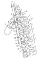
図1は、本発明の実施形態に係る可変動弁装置を4気筒エンジンの吸気バルブに適用した全体構成を示す。同図において、3はエンジンのクランク軸に同期して軸心X(図2、図10等参照)回りに回転するカムシャフトである。このエンジンは1つの気筒に2つの吸気バルブ1,2と2つの排気バルブ(図示省略)とを有する4バルブのダブルオーバヘッドカム方式を採用したものである。つまり、同一気筒において2つの吸気バルブ1,2がカムシャフト3の軸方向に並設されていることになる。尚、吸気バルブ1,2の軸線及び排気バルブの軸線は、シリンダボアセンターに対して傾斜(上方に向かってエンジン外側(吸気バルブ1,2と排気バルブとで互いに反対側)に傾斜)している。
(Basic configuration of variable valve operating device)
FIG. 1 shows an overall configuration in which a variable valve device according to an embodiment of the present invention is applied to an intake valve of a four-cylinder engine. In the figure,
上記カムシャフト3における後述の偏心部6以外の部分(カムシャフト本体)には、各気筒毎に一対の揺動カム4,5が揺動自在に支持されている。これら一対の揺動カム4,5は、上記2つの吸気バルブ1,2にそれぞれ対応するように互いに一体形成されてなっている。つまり、両揺動カム4,5は、その間に設けた略円筒状の連結部50で互いに連結されてなっていて、カムシャフト3の軸心(カムシャフト3の回転中心)X回りに一体で揺動する。そして、1つの気筒における吸気バルブ1,2の各々は、上記揺動カム4,5によって、中間部材としての直動式タペット21(図2参照)を介してそれぞれリフトされ、そのバルブリフト量及びバルブタイミングがエンジンの運転状態に応じて変更されるようになっている。
A pair of
上記各気筒における吸気バルブ1,2のリフト量及びタイミングの変更のために、上記カムシャフト3には、該カムシャフト3の回転時にカムシャフト3の軸心X回りに偏心して回転する4つの偏心部6がそれぞれ一体的に設けられている。これら4つの偏心部6は、各々、カムシャフト3の軸心Xに対して偏心しかつ平行に延びる中心軸を有する円形偏心カムからなっていて、各気筒毎にそれぞれ対応して設けられている。この各偏心カムはカムシャフト本体よりも大きい径を有している。そして、上記各偏心部6には、駆動リンク7の一端部が回転自在に外嵌めされ、この駆動リンク7の他端部と上記揺動カム5とが1本の連結リンク8によって連結されている。また、上記カムシャフト3と平行にコントロールシャフト11が設けられており、このコントロールシャフト11には、4つのコントロールアーム(コントロール部材)12がそれぞれ結合固定されている。この各コントロールアーム12の先端部と上記駆動リンク7の他端部とが規制リンク13によって連結されている。この規制リンク13は、上記偏心部6の回転に伴う駆動リンク7の変位を上記連結リンク8を介して上記揺動カム4,5が揺動するように規制するものである。このことで、上記連結リンク8及び規制リンク13は、揺動カム5と駆動リンク7とを連結しかつ上記偏心部6の回転に伴う該駆動リンク7の変位を揺動カム5(及び揺動カム4)が揺動するように規制するリンク機構を構成する。
In order to change the lift amount and timing of the
上記コントロールシャフト11には、円周の一部のみに歯が形成されたウォーム歯車14が結合されている。このウォーム歯車14の歯に、モータ15で回転駆動されるウォーム16が噛み合っている。そうして、エンジンの運転状態に応じてモータ15を作動させて上記コントロールアーム12をコントロールシャフト11の軸心回りに回動させることで、上記規制リンク13の位置(リンク機構の位置)を変えて吸気バルブ1,2のリフト量及びタイミングを変更させるようになっている。この場合、コントロールアーム12は、エンジン負荷が高くなるほど吸気バルブ1,2のリフト量が大きくなるように制御される。以下、可変動弁装置について具体的に説明する。
The
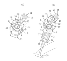
図2(b)に示すように、吸気バルブ2のステム上端に直動式タペット21が設けられ、該タペット21に揺動カム5が当接している。吸気バルブ2は、タペット21内部に設けられたリテーナ22とシリンダヘッドに設けられたリテーナ23との間の位置(所定位置)に設けられたばね付勢手段としてのバルブスプリング24によって吸気ポート25を閉じる方向(バルブリフト方向とは反対方向)に付勢されている。このバルブスプリング24の構成については後に詳細に説明する。尚、吸気バルブ1も吸気バルブ2と同様の構成になっている。
As shown in FIG. 2B, a
上記連結リンク8の一端部は、揺動カム5において揺動カム4とは反対側面におけるカムノーズとは揺動中心を挟んで反対側部分に、ピン31にて回動自在に連結され、規制リンク13の一端部は、コントロールアーム12の先端部にピン32にて回動自在に連結されている。そうして、この連結リンク8と規制リンク13とは、駆動リンク7を中間において連係している。すなわち、連結リンク8及び規制リンク13の各々の他端部は、駆動リンク7の他端部に連結ピン33によって同軸で回動自在に連結されている。尚、上記ピン31〜33はいずれもカムシャフト3と平行に延びている。
One end portion of the connecting
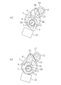
上記駆動リンク7と連結リンク8との連結ピン33はカムシャフト3の上方に配置され、該連結点の側方にコントロールアーム12の回動中心(コントロールシャフト11の軸心)が配置されている。コントロールアーム12の先端のピン32は規制リンク13の回動中心である。このピン32をコントロールシャフト11の下方に配置した図2は、大リフト制御時の状態を示し、図3に示すようにコントロールアーム12の回動によってピン32を上方へ移動させてカムシャフト3の上方に位置付けると、小リフト制御時の状態となる。
The
図2(a)及び(b)に示すように、駆動リンク7の位置は偏心部6の回転に伴って変化し、この駆動リンク7の位置変化により揺動カム5が連結リンク8を介して、吸気バルブ2のリフト量が零となるリフト量零状態(図2(a)参照)と、リフト量がピークとなるリフトピーク状態(図2(b)参照)との間で揺動する。上記リフト量零状態では、揺動カム5は、カムシャフト3の軸方向一方側から見て、該揺動カム5のカムノーズ先端が吸気バルブ2の軸線の延長線両側のいずれか一方(この実施形態では、シリンダボアセンターとは反対側(図2の右側))に位置するようになされている。そして、揺動カム5は、カムシャフト3の軸方向一方側から見て、このリフト量零状態からカムシャフト3の回転方向と同じ方向(この実施形態では、図2で時計回り方向(右回り))に回動しながら吸気バルブ2をリフトさせるようになっている。つまり、カムシャフト3の回転方向と揺動カム5のバルブリフト時の回動方向とが同じになっている。尚、小リフト制御時の図3の場合も、上記大リフト制御時と同様であり、吸気バルブ1と揺動カム4との関係は、吸気バルブ2と5揺動カム5との関係と同じである。
As shown in FIGS. 2 (a) and 2 (b), the position of the
図4に上記可変動弁装置の作動を具体的に示す。尚、同図では、コントロールアーム12、連結リンク8及び規制リンク13については直線で表している。また、T3は偏心部6の中心(偏心カムの中心軸)の回転軌跡である。また、上述の如く吸気バルブ1と揺動カム4との関係は吸気バルブ2と揺動カム5との関係と同じであって、揺動カム4は揺動カム5と同様に働くので、以下では、吸気バルブ2と揺動カム5との関係で当該可変動弁装置を説明する。
FIG. 4 specifically shows the operation of the variable valve operating apparatus. In the figure, the
まず、揺動カム5の周面には、曲率半径が所定角度範囲一定になっている基円面(ベースサークル区間)θ1と、該θ1に続いて曲率半径が漸次大きくなっているカム面(リフト区間)θ2とが形成されている。カムシャフト3(偏心部6)の回転方向は図4で時計回り方向に設定されている。図4に実線で示す状態は、コントロールアーム12が大リフト制御時の位置とされ、かつ駆動リンク7の連結ピン33が最も上方に位置付けられたリフトピーク状態である。このときに、揺動カム5はカム面θ2のカムノーズ先端側の端がタペット21に当接(後述の如く、この実施形態では、カムシャフト3の軸方向一方側から見てタペット21の略中心部に当接)した状態になるように設けられている。
First, on the peripheral surface of the
図4の実線状態において、偏心部6が回転すると、それに伴って駆動リンク7が変位するが、その変位は規制リンク13によって規制される。すなわち、規制リンク13はコントロールシャフト11の下方に配置されたピン32を中心に回動するから、駆動リンク7の連結ピン33は、偏心部6が1回転する度に、ピン32を中心として往復円弧運動T1をすることになる(規制リンク13は実線状態と破線状態との間で往復回動する)。
In the state of the solid line in FIG. 4, when the
上記連結ピン33の往復円弧運動T1に伴って、駆動リンク7に連結リンク8で連結された揺動カム5は、実線状態と破線状態との間で揺動運動をする。揺動カム5は破線状態ではその基円面θ1がタペット21に接しており、バルブリフト量は零(吸気バルブ1,2は閉)となる。そして、連結ピン33が上方に移動するときに、ピン31も上方に移動して、揺動カム5におけるカムノーズとは揺動中心を挟んで反対側部分が上方に移動し、これにより、カムノーズは下方(吸気バルブ2側)に移動して、吸気バルブ2をリフトさせる。
Along with the reciprocating arc motion T1 of the connecting
上記揺動カム5が図4の実線状態(大リフト制御時のリフトピーク状態)と破線状態(リフト量零状態)との間で揺動するときの吸気バルブ1,2のリフト特性を図5にL1で示す。
FIG. 5 shows the lift characteristics of the
次にコントロールアーム12を図4に実線で示す状態からコントロールシャフト11の軸心回りに上方へ回動させて、規制リンク13の回動中心であるピン32を大リフト制御時よりもカムシャフト3の回転方向手前側に位置付けた一点鎖線で示す略水平な状態にすると、小リフト制御時の状態となる。すなわち、偏心部6が回転するとき、駆動リンク7の連結ピン33は規制リンク13によって変位が規制され、コントロールシャフト11の側方に配置されたピン32を中心として往復円弧運動T2をすることになる(規制リンク13は一点鎖線状態と二点鎖線状態との間で往復回動する)。
Next, the
上記連結ピン33の往復円弧運動T2に伴って、駆動リンク7に連結リンク8で連結された揺動カム5は、一点鎖線状態と破線状態との間で揺動運動をする。尚、本例の場合、連結ピン33が往復円弧運動T2によってリフト量零状態になったときの位置(二点鎖線位置)は、往復円弧運動T1によってリフト量零状態になったときの位置(破線位置)と略同じであるから、連結ピン33が往復円弧運動T2によって二点鎖線位置に位置付けられたときの揺動カム5の状態は破線状態で代用した。
Along with the reciprocating arc motion T2 of the connecting
揺動カム5が図4の一点鎖線状態(小リフト制御時のリフトピーク状態)と破線状態(リフト量零状態)との間で揺動するときの吸気バルブ1,2のリフト特性を図5にL2で示す。
FIG. 5 shows the lift characteristics of the
図5に示すように、大リフト制御時から小リフト制御時へ移行すると、リフトピーク状態でのバルブリフト量が小さくなり、このことで、コントロールアーム12によるリンク機構(規制リンク13)の位置変更によりバルブリフト量が変化することになる。尚、バルブリフト量は、コントロールアーム12の図4の実線状態と一点鎖線状態との間における回動位置に応じて無段階に変化させることができる。
As shown in FIG. 5, when shifting from the large lift control to the small lift control, the valve lift amount in the lift peak state becomes small, and this changes the position of the link mechanism (restriction link 13) by the
そうして、大リフト制御時から小リフト制御時への移行にあたっては、コントロールアーム12の回動により規制リンク13の回動中心であるピン32を移動させて連結ピン33の往復円弧運動の位置をT1からT2へ、すなわち、カムシャフト3の回転方向手前側に移動させている。これにより、大リフト制御時にはリフトピーク状態での偏心部6の中心はTaに位置するが、小リフト制御時にはリフトピーク状態での偏心部6の中心はTbに移動する。つまり、大リフト制御時から小リフト制御時に移行したとき、リフトピーク状態ではTaとTbとに関する中心角θ3だけ進角することになる。
Thus, when shifting from the large lift control to the small lift control, the
このように、リフトピーク状態でのバルブリフト量を小さくしていくと、バルブリフトのピーク時が進角するから、図5に示すように、バルブリフト量の大小に拘わらず吸気バルブ1,2の開弁開始時期を略揃える上で有利になる。このように開弁開始時期を揃えるための各部材の位置関係は、揺動カム4,5のバルブリフト時の回動方向がカムシャフト3の回転方向と同じである場合の方が異なる場合よりも容易に得られる。
As described above, when the valve lift amount in the lift peak state is reduced, the peak time of the valve lift is advanced. Therefore, as shown in FIG. This is advantageous in substantially aligning the valve opening start times. Thus, the positional relationship of each member for aligning the valve opening start timing is different when the rotation direction of the
しかも、上記連結リンク8と規制リンク13とが駆動リンク7を中間において連係しているから、コントロールアーム12によって規制リンク13の位置を大きく変更させて揺動カム5によるバルブリフト量を大きく変化させることができ、このバルブリフト量の制御のみでエンジンの運転状態に応じた最適な吸気量を得ることができるため、スロットルレスとしてポンピングロスを低減することができるとともに、大リフト制御時の吸気充填効率を向上させることができる。
Moreover, since the connecting
また、上記実施形態では、各気筒において、揺動カム4と揺動カム5とを互いに一体形成して、揺動カム5と駆動リンク7とを1本の連結リンク8で連結し、該連結リンク8及び規制リンク13各々の一端を駆動リンク7に連結する構成としたから、部品点数を少なくして構成を簡単にすることができ、可変動弁装置のコンパクト化及び軽量化に有利になる。しかも、コントロールアーム12の回動中心(コントロールシャフト11の軸心)を駆動リンク7の連結ピン33の側方に配置したから、可変動弁装置全体が嵩高なものにならず、エンジンの全高が増大することを防止することができる。
In the above embodiment, in each cylinder, the rocking
(リンク機構の適正化)
可変動弁装置のコンパクト化を図る方策の一つとして、カムシャフト3の偏心部6を小さくする(つまり偏心量を小さくする)ことが挙げられる。また、可変動弁装置では、狭角リフト化の実現、つまり、小さい開弁角(カムシャフト3の回転角)で大きなバルブリフト量を得て吸気バルブ1,2の早閉じを実現し、それによってポンピングロスを低減して燃費の向上を図りたいという要求がある。
(Optimization of link mechanism)
One of the measures for reducing the size of the variable valve operating apparatus is to reduce the
可変動弁装置のコンパクト化を図るべく偏心部6の偏心量を小さくした場合、駆動リンク7の連結ピン33の往復円弧運動の角度変化は小さくなる。この状態で狭角リフト化を図るには、連結ピン33の角度の微小変化に対して、揺動カム5のピン31(以下、揺動カムピンという)の角度変化を大きくする必要がある。
When the amount of eccentricity of the
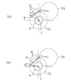
このことについて、図6を参照しながら説明する。図6(a)は、連結ピン33の往復円弧運動の軌跡T4と、揺動カムピン31の揺動運動の軌跡T5とをそれぞれ示している(軌跡T4,T5は実際には円弧となるが、同図では円で示している)。また、図6(b)も同様であり、軌跡T4,T5は、図6(a)及び(b)で同じである。
This will be described with reference to FIG. FIG. 6A shows a trajectory T4 of the reciprocating arc motion of the connecting
図6(a)は、揺動カムピン31の角度変化の接線が、連結ピン33の角度変化の接線に対して直角に比較的近い角度で交わる箇所で、揺動カムピン31を揺動させた場合を示していて、この場合、連結リンク8の長さは比較的短くなる。これに対し、図6(b)は、揺動カムピン31の角度変化の接線が、連結ピン33の角度変化の接線に対して略平行となる箇所で、揺動カムピン31を揺動させた場合を示していて、この場合、連結リンク8の長さは比較的長くなる。
FIG. 6A shows a case where the
図6(a)及び(b)を比較すると、連結ピン33の角度がdxだけ微小変化したときに、揺動カムピン31のdx方向への変位量は図6(a)及び(b)共に同程度であるが、図6(a)の場合における揺動カムピン31の角度変化(α)は、図6(b)の場合における揺動カムピン31の角度変化(β)よりも大きいことがわかる。図6(a)に示すように、揺動カムピン31を連結ピン33に近接した位置で、その揺動カムピン31を揺動させることで、揺動カム5を効率よく揺動させることが可能になり、可変動弁装置のコンパクト化を図りつつ、狭角リフト化の実現が図られる。また、連結リンク8の長さが短くなることから、可変動弁装置の更なるコンパクト化が図られると共に、リンクの剛性の点でも有利になる。さらに、揺動カムピン31を連結ピン33に近接させることで連結リンク8が他部材と干渉しなくなることから、連結リンク8の屈曲を小さくすることができ、リンクの高剛性の点でより一層有利になる。
Comparing FIGS. 6A and 6B, when the angle of the connecting
このように、揺動カム5の揺動カムピン31を連結ピン33に近接させることで揺動カムピン31を効率よく揺動させることができるが、吸気バルブ2のリフト量と開弁角とは、揺動カム5のカムノーズをどのように配置させるかによって決定される。
As described above, the
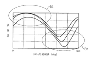
このことについて、図7及び図8を参照しながら説明する。図7は、図6(a)に示すリンク構造において、カムシャフト3の回転角(クランク角)に対する揺動角の変化、つまり揺動プロファイルを示している。この揺動プロファイルにおいて、E1で囲まれた領域は、連結ピン33がその往復円弧運動の最下部ないしその近傍に位置するときに対応し、E2で囲まれた領域は、連結ピン33がその往復円弧運動の最上部ないしその近傍に位置するときに対応する。これによると、E1で囲まれた領域は、クランク角変化に対する揺動角の変化が緩やかであり、E2で囲まれた領域を含めてE1以外の領域ではクランク角変化に対する揺動角の変化が急峻である。尚、揺動プロファイルは、コントロールアーム12の図4の実線状態と一点鎖線状態との間における回動位置によって変化するが、上記の傾向は同じである。
This will be described with reference to FIGS. FIG. 7 shows a change in swing angle with respect to the rotation angle (crank angle) of the
ここで、図6(a)に示すリンク構造においては、図8(a)に示すように、連結リンク8により揺動カム5をタペット21から引き離す方向に引っ張る(同図の実線の矢印参照)ことで吸気バルブ2を開弁させる(カムシャフト3の軸方向一方側から見て、揺動カム5のバルブリフト時の回動方向がカムシャフト3の回転方向と同じになっている)場合と、図8(b)に示すように、揺動カム5をタペット21側に押す(同図の矢印参照)ことで、吸気バルブ2を開弁させる(カムシャフト3の軸方向一方側から見て、揺動カム5のバルブリフト時の回動方向がカムシャフト3の回転方向と反対になっている)場合との2つが考えられる。図8(a)の場合には、揺動カム5のカムノーズは揺動中心を挟んで揺動カムピン31とは逆側に位置し、図8(b)の場合には、カムノーズは揺動中心に対して揺動カムピン31と同じ側に位置する。そして、図8(b)の場合には、連結ピン33が最下部ないしその近傍に位置するときにバルブがリフトされた状態にあるので、このバルブリフト状態においては、図7におけるE1領域の揺動プロファイル、つまり揺動角の変化が緩やかな揺動プロファイルを利用することになり、その結果、開弁角が大きくなる。これに対し、図8(a)の場合には、連結ピン33が最上部ないしその近傍に位置するときにバルブがリフトされた状態にあるので、このバルブリフト状態においては、図7におけるE2領域の揺動プロファイル、つまり揺動角の変化が急峻な揺動プロファイルを利用することになり、その結果、開弁角が小さくなる。したがって、狭角リフト化を実現するには、図8(a)に示すように、揺動カム5のカムノーズを揺動中心を挟んで揺動カムピン31とは逆側に設けることが必要となる。また、この場合、小リフト制御時におけるE2領域の揺動プロファイルを大リフト制御時よりも急峻にすることで、小リフト制御時の方が大リフト制御時よりもクランク角変化に対する揺動角の変化を急峻にすることができ、これにより、ポンピングロスがより一層改善されて、燃費改善効果を増大させることができる。
Here, in the link structure shown in FIG. 6A, as shown in FIG. 8A, the connecting
さらに、リフトピーク状態から吸気バルブ2の閉じ方向に揺動カム5が戻る際に、バルブスプリング反力がカムノーズに作用するが、カムノーズを揺動中心を挟んで揺動カムピン31とは逆側に設けることによって、その揺動カムピン31には、揺動カム5を戻す方向のモーメントが作用する(図8(a)の破線の矢印参照)。それによって、揺動カムピン31に入力される荷重が緩和されるという利点がある。
Further, when the
以上、説明したように、可変動弁装置のコンパクト化と狭角リフト化とを両立させるためにリンク機構を最適化させると、カムシャフト3、コントロールシャフト11、揺動カム4,5、偏心部6、駆動リンク7、連結リンク8、規制リンク13及びコントロールアーム12の配置は、図8(a)に示すようになる。同図は、上述したように、リフトピーク状態を示していて、コントロールアーム12、連結リンク8及び規制リンク13によって、カムシャフト3の軸方向一方側から見て略N字が形成されるように、これらコントロールアーム12、連結リンク8、規制リンク13がそれぞれ配置される。また、リフトピーク状態において、連結ピン33が、コントロールアーム12の回動中心(コントロールシャフト11の軸心)に近接して配設される。そして、揺動カム4,5がカムシャフト3の回転方向と同じ方向に回動しながら吸気バルブ1,2をリフトさせることになる。
As described above, when the link mechanism is optimized in order to achieve both compactness and narrow angle lift of the variable valve device, the
(バルブスプリングの詳細構成)
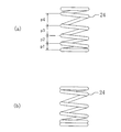
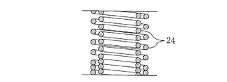
図9(a)に示すように、上記吸気バルブ1,2をリフト方向と反対方向にそれぞれ付勢する各バルブスプリング24は、圧縮コイルスプリングからなっていて、自然状態(圧縮量が零の状態)において互いに異なる4種の線間ピッチp1〜p4を有している。この実施形態では、1巻き毎に線間ピッチが変化しかつ一方端から他方端に向かって線間ピッチが長くなっているが、これに限らず、各線間ピッチを有する部分がバルブスプリング24の長さ方向のどの位置にあってもよく、複数巻き連続して同じ線間ピッチであってもよい。このように互いに異なる4種の線間ピッチp1〜p4を有することで、このバルブスプリング24を自然状態から圧縮していくと、その特性は図10のようになる。すなわち、最初に最も小さい線間ピッチp1の部分が密着状態となり、この時点(図10に示すP点)でばね定数が大きくなるように変化し、更に圧縮していくと、2番目に小さい線間ピッチp2の部分も密着状態となり、この時点(Q点)でばね定数が更に大きくなるように変化し、続いて、3番目に小さい線間ピッチp2の部分も密着状態となり、この時点(R点)でばね定数が更に大きくなるように変化する。要するに、自然状態からの圧縮時にばね定数の変化点が3つ(P点、Q点及びR点)存在して、ばね定数が4段階に変化するようになっている。そして、上記バルブスプリング24は、自然状態から圧縮して1つ目のばね定数変化点(P点)を越えた圧縮量(S点)で上記所定位置にセットされるようになっている。このセットされた状態を図9(b)に示す。つまり、バルブスプリング24のセット状態では、最も小さい線間ピッチp1の部分が密着状態となっている。このセット状態から更に圧縮した、2つ目及び3つ目のばね定数変化点(Q点及びR点)を含む領域(S点からF点までの領域)が、後述のフルリフト期間に相当する。尚、F点では、最も大きい線間ピッチp4の部分が密着状態とはなっていない。
(Detailed configuration of valve spring)
As shown in FIG. 9A, each
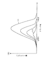
上記の如くバルブスプリング24が構成されかつセットされることで、吸気バルブ1,2がリフト量零の状態からコントロールアーム12によるリフト量の変化範囲の最大値の状態になるまでリフトされるフルリフト期間内に、バルブスプリング24のばね定数が互いに異なる3つのばね定数一定期間(小リフト側から第1ばね定数一定期間(図10及び図11に示すD1期間)、第2ばね定数一定期間(D2期間)及び第3ばね定数一定期間(D3期間)という)が含まれることになる。すなわち、吸気バルブ1,2のフルリフト期間内においては、バルブスプリング24のばね定数の変化点が2つ(Q点及びR点)存在して、ばね定数が3段階に変化するようになっている。そして、上記フルリフト期間内における小リフト側のばね定数一定期間のばね定数が大リフト側のばね定数一定期間よりも小さくなっている。つまり、第1ばね定数一定期間D1のばね定数が最も小さく、第3ばね定数一定期間D3のばね定数が最も大きく、第2ばね定数一定期間D2のばね定数が中間の値となっている。
As the
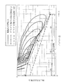
図11は、上記バルブスプリング24の付勢力及び揺動カム5の直動式タペット21に対する押圧力を、バルブリフト量との関係で示すものである。これら付勢力及び押圧力は、バルブリフト方向を正としていて、同図では負の値となっており、図の下側ほど力の絶対値が大きいことになる。そして、揺動カム5の押圧力は、9種類のリフト量の各々の場合において、揺動カム5がリフトピーク状態からリフト量零状態に向かって回動しているときのものであり、各リフト量に対応するエンジンの最大回転数に基づく動弁系の慣性力によって決まるものである。このように揺動カム5がリフトピーク状態からリフト量零状態に向かって回動しているときには、負の加速度のために慣性力(つまり押圧力)が負となり、このため、図11に示す揺動カム5の押圧力は、実際には、揺動カム5がタペット21から離れようとする力である。尚、バルブスプリング24の付勢力の絶対値は、図10で示したS点からF点までの領域における圧縮荷重と同じであり、図11のグラフの横軸のバルブリフト量は、バルブスプリング24のセット時からの圧縮量と同じである。
FIG. 11 shows the urging force of the
ここで、揺動カム5がリフトピーク状態からリフト量零状態に向かって回動しているときに、揺動カム5がタペット21から離れないようにするためには、上記バルブスプリング24の付勢力の絶対値が上記揺動カム5の押圧力の絶対値(タペット21から離れようとする力)よりも大きくなければならない。一方、動弁系の機械抵抗ロスを低減するためには、上記付勢力の絶対値は出来る限り小さい方が望ましい。したがって、付勢力の絶対値は、押圧力の絶対値に対して僅かに大きい程度が望ましい。そして、従来より使用されているバルブスプリングのように、吸気バルブ1,2のフルリフト期間の全体に亘ってばね定数が一定であるもの(図11の破線参照)では、大リフト制御時における高回転にる動弁系の大きな慣性力に対応してバルブスプリングを設計するため、小リフト側においては付勢力と押圧力との差が大きくなり、仮にこの付勢力に押圧力を近づけるようにすると、小リフト制御時にエンジン回転限界を高くできることになるが、小リフト制御を行うのは、エンジン低回転低負荷時であり、このため、小リフト制御時にエンジン回転限界を高める必要はなく、結局、付勢力の絶対値と押圧力の絶対値との差の分だけ動弁系の機械抵抗ロスにより無駄なエネルギーを消費することになり、燃費の改善効果が十分に得られなくなってしまう。
Here, in order to prevent the
これに対し、本実施形態では、図11において一点鎖線で示すように、吸気バルブ1,2のフルリフト期間にバルブスプリング24のばね定数が2回変化するようにしているので、付勢力の絶対値と押圧力の絶対値との差がフルリフト期間全体に亘って略均一となる。特に、本実施形態では、上記フルリフト期間内における小リフト側のばね定数一定期間の始点及び終点にそれぞれ対応する両リフト量の差を、大リフト側のばね定数一定期間よりも小さくしている。すなわち、第1ばね定数一定期間D1の始点(S点)及び終点(Q点)にそれぞれ対応する両リフト量の差(図11におけるSQ間の横軸に沿った長さ(S点からQ点まで圧縮したときの圧縮量))を最も小さくし、第3ばね定数一定期間D3の始点(R点)及び終点(F点)にそれぞれ対応する両リフト量の差(図11におけるRF間の横軸に沿った長さ(R点からF点まで圧縮したときの圧縮量))を最も大きくし、第2ばね定数一定期間D2の始点(Q点)及び終点(R点)にそれぞれ対応する両リフト量の差(図11におけるQR間の横軸に沿った長さ(Q点からR点まで圧縮したときの圧縮量))を中間の値としている。このようにすることで、小リフト側においてばね定数を木目細かく変化させることができ、小リフト側のばね定数を最適なものにすることができる。この結果、小リフト制御時には、動弁系の機械抵抗ロスを低減することができ、バルブ開弁開始時期を略揃えること及び狭角リフト化を実現することと相俟って、燃費を効果的に低減することができる。一方、エンジン高回転時における大リフト制御時には、高回転による動弁系の大きな慣性力に対応して第3ばね定数一定期間D3のばね定数を大きくすることで、エンジン回転限界を高めることができる。
In contrast, in the present embodiment, as indicated by the one-dot chain line in FIG. 11, the spring constant of the
尚、上記実施形態では、吸気バルブ1,2のフルリフト期間内に、バルブスプリング24のばね定数が互いに異なる3つのばね定数一定期間が含まれるようにしたが、ばね定数が互いに異なるばね定数一定期間が2つ以上含まれていればよい(ばね定数変化点が少なくとも1つ存在していればよい)。このため、自然状態からの圧縮時には、ばね定数変化点が2つ以上存在すればよい。但し、バルブスプリング24のセット時に、最も小さい線間ピッチの部分を密着状態にする必要は必ずしもないので、その部分を密着状態にしてセットしない場合には、自然状態からの圧縮時とフルリフト期間内とで同じ数のばね定数変化点が存在すればよい。
In the above-described embodiment, the three constants of the spring constant of the
また、上記実施形態では、1つの吸気バルブについて1つのバルブスプリング24を設けたが、図12に示すように、複数(同図では、2つ)のバルブスプリング24を同心状にして上記所定位置にセットするようにしてもよい。この場合、各バルブスプリング24は上記実施形態と同様の構成とし、吸気バルブ1,2のフルリフト期間内に、複数のバルブスプリング24の合成ばね定数の変化点が少なくとも1つ存在するようにすればよい。そして、上記複数のバルブスプリング24間で線間ピッチを異ならせることで、合成ばね定数の変化点の数を容易に増大させることもでき、付勢力を適切な値に設定し易くなる。
In the above embodiment, one
さらに、上記実施形態では、ばね付勢手段を圧縮コイルスプリングで構成したが、圧縮コイルスプリングに限らず、板ばね等で構成してもよい。 Furthermore, in the said embodiment, although the spring biasing means was comprised with the compression coil spring, you may comprise not only with a compression coil spring but with a leaf | plate spring.
また、上記実施形態では、揺動カム4,5が中間部材としての直動式タペット21を介して吸気バルブ1,2をそれぞれリフトさせるようにしたが、中間部材がロッカアームであってもよい。また、揺動カム4,5が、カムシャフト3の軸方向一方側から見て、該カムシャフト3の回転方向と反対方向に回動しながら吸気バルブ1,2をそれぞれリフトさせる図8(b)のような構成であっても、本発明を適用することができる。さらに、リンク機構は、上記実施形態のような連結リンク8及び規制リンク13に限らず、揺動カム4,5と駆動リンク7とを連結しかつ偏心部6の回転に伴う該駆動リンク7の変位を揺動カム4,5が揺動するように規制するものであればどのような構成であってもよく、コントロール部材は、上記実施形態のようなコントロールアーム12に限らず、上記リンク機構の位置を、揺動カム4,5による吸気バルブ1,2のリフト量が変化するように変更するものであればよい。さらにまた、本発明は、排気バルブにも適用することができる。
In the above embodiment, the
加えて、本発明は、ばね付勢手段によりリフト方向とは反対方向に付勢されたバルブのリフト量を変化させる可変動弁装置であれば、どうような構成のものにも適用することができ、例えば従来技術として挙げた特許文献1や特許文献2のものにも適用することができるとともに、バルブのリフト量を互いに異ならせる複数のカムを有していて該カムを選択切換えすることでバルブリフト量を変化させるものにも適用することができる。
In addition, the present invention can be applied to any configuration as long as it is a variable valve gear that changes the lift amount of the valve biased in the direction opposite to the lift direction by the spring biasing means. For example, it can be applied to those of
本発明は、エンジンの運転状態に応じて、エンジンの吸排気バルブの開閉時期やバルブリフト量を変化させるようにするエンジンの可変動弁装置に有用である。 INDUSTRIAL APPLICABILITY The present invention is useful for a variable valve operating device for an engine that changes the opening / closing timing and valve lift amount of the intake / exhaust valve of the engine according to the operating state of the engine.
1,2 吸気バルブ
3 カムシャフト
4,5 揺動カム
6 偏心部
6a ピン部
6b 支持部
6c 支持部
6d 規制部
7 駆動リンク
8 連結リンク(リンク機構)(第1リンク)
11 コントロールシャフト
12 コントロールアーム(コントロール部材)
13 規制リンク(リンク機構)(第2リンク)
21 直動式タペット(中間部材)
24 バルブスプリング(ばね付勢手段)
DESCRIPTION OF
11
13 Restriction link (link mechanism) (second link)
21 Direct acting tappet (intermediate member)
24 Valve spring (spring biasing means)
Claims (6)
上記バルブがリフト量零の状態からリフト量の変化範囲の最大値の状態になるまでリフトされるフルリフト期間内に、上記ばね付勢手段のばね定数が互いに異なる2つ以上のばね定数一定期間が含まれているとともに、該フルリフト期間内における小リフト側のばね定数一定期間のばね定数が大リフト側のばね定数一定期間よりも小さいことを特徴とするエンジンの可変動弁装置。 A variable valve operating apparatus for an engine configured to be capable of changing a lift amount of a valve biased in a direction opposite to a lift direction by a spring biasing means,
Two or more spring constant constant periods in which the spring constants of the spring urging means are different from each other within the full lift period in which the valve is lifted from the state where the lift amount is zero to the maximum value in the range of change in the lift amount. A variable valve operating system for an engine, characterized in that the spring constant of a small lift-side spring constant during the full lift period is smaller than the large lift-side spring constant constant period.
ばね付勢手段は、圧縮コイルスプリングからなり、
上記圧縮コイルスプリングは、自然状態からの圧縮時にばね定数の変化点が2つ以上存在するものであって、バルブのフルリフト期間内においては、ばね定数の変化点が少なくとも1つ存在するように所定位置にセットされていることを特徴とするエンジンの可変動弁装置。 The variable valve operating apparatus for an engine according to claim 1,
The spring biasing means comprises a compression coil spring,
The compression coil spring has two or more spring constant change points when compressed from a natural state, and the predetermined value is set so that at least one spring constant change point exists during the full lift period of the valve. A variable valve operating device for an engine characterized by being set to a position.
ばね付勢手段は、自然状態において互いに異なる複数種の線間ピッチを有する圧縮コイルスプリングからなることを特徴とするエンジンの可変動弁装置。 The variable valve operating apparatus for an engine according to claim 1,
The variable valve operating apparatus for an engine, wherein the spring urging means comprises compression coil springs having a plurality of different line pitches in a natural state.
ばね付勢手段は、所定位置に互いに同心状にセットされた複数の圧縮コイルスプリングからなり、
バルブのフルリフト期間内に、上記複数の圧縮コイルスプリングの合成ばね定数の変化点が少なくとも1つ存在していることを特徴とするエンジンの可変動弁装置。 The variable valve operating apparatus for an engine according to claim 1,
The spring biasing means comprises a plurality of compression coil springs set concentrically with each other at a predetermined position,
A variable valve operating apparatus for an engine, wherein at least one change point of a composite spring constant of the plurality of compression coil springs exists within a full lift period of the valve.
バルブのフルリフト期間内における小リフト側のばね定数一定期間の始点及び終点にそれぞれ対応する両リフト量の差が、大リフト側のばね定数一定期間よりも小さいことを特徴とするエンジンの可変動弁装置。 The variable valve operating apparatus for an engine according to claim 1,
A variable valve for an engine characterized in that a difference between both lift amounts corresponding to a start point and an end point of a spring constant constant period on the small lift side within a full lift period of the valve is smaller than that on the large lift side. apparatus.
上記カムシャフトに設けられ、該カムシャフトの軸心回りに偏心して回転する偏心部と、
上記カムシャフトの軸心回りに揺動可能に設けられ、中間部材を介してバルブをリフトさせる揺動カムと、
上記カムシャフトの偏心部に回転自在に外嵌めされた駆動リンクと、
上記揺動カムと駆動リンクとを連結するとともに、上記偏心部の回転に伴う該駆動リンクの変位を上記揺動カムが揺動するように規制するリンク機構と、
上記リンク機構の位置を、上記揺動カムによる上記バルブのリフト量が変化するように変更するコントロール部材と、
上記バルブをリフト方向とは反対方向に付勢するばね付勢手段とを備えたエンジンの可変動弁装置であって、
上記揺動カムにより上記バルブがリフト量零の状態からリフト量の変化範囲の最大値の状態になるまでリフトされるフルリフト期間内に、上記ばね付勢手段のばね定数が互いに異なる2つ以上のばね定数一定期間が含まれているとともに、該フルリフト期間内における小リフト側のばね定数一定期間のばね定数が大リフト側のばね定数一定期間よりも小さいことを特徴とするエンジンの可変動弁装置。 A camshaft that rotates in synchronization with the crankshaft of the engine;
An eccentric portion provided on the camshaft and rotating eccentrically about the axis of the camshaft;
A swing cam provided so as to be swingable about the axis of the camshaft and for lifting the valve via an intermediate member;
A drive link rotatably fitted on the eccentric part of the camshaft;
A link mechanism that connects the swing cam and the drive link, and restricts the displacement of the drive link accompanying the rotation of the eccentric portion so that the swing cam swings;
A control member that changes the position of the link mechanism so that the lift amount of the valve by the swing cam changes;
A variable valve operating system for an engine comprising spring urging means for urging the valve in a direction opposite to the lift direction,
Two or more spring constants of the spring urging means are different from each other during a full lift period in which the swing cam lifts the valve from a lift amount zero state to a maximum value of the lift amount change range. A variable valve operating system for an engine characterized by including a constant spring constant period and a spring constant of a small spring side constant constant within the full lift period being smaller than a constant period of a large lift side spring constant .
Priority Applications (1)
| Application Number | Priority Date | Filing Date | Title |
|---|---|---|---|
| JP2004103601A JP2005291011A (en) | 2004-03-31 | 2004-03-31 | Variable valve gear for engine |
Applications Claiming Priority (1)
| Application Number | Priority Date | Filing Date | Title |
|---|---|---|---|
| JP2004103601A JP2005291011A (en) | 2004-03-31 | 2004-03-31 | Variable valve gear for engine |
Publications (1)
| Publication Number | Publication Date |
|---|---|
| JP2005291011A true JP2005291011A (en) | 2005-10-20 |
Family
ID=35324240
Family Applications (1)
| Application Number | Title | Priority Date | Filing Date |
|---|---|---|---|
| JP2004103601A Abandoned JP2005291011A (en) | 2004-03-31 | 2004-03-31 | Variable valve gear for engine |
Country Status (1)
| Country | Link |
|---|---|
| JP (1) | JP2005291011A (en) |
Cited By (1)
| Publication number | Priority date | Publication date | Assignee | Title |
|---|---|---|---|---|
| US8011336B2 (en) | 2007-10-05 | 2011-09-06 | Honda Motor Co., Ltd. | Variable valve opening property internal combustion engine |
-
2004
- 2004-03-31 JP JP2004103601A patent/JP2005291011A/en not_active Abandoned
Cited By (1)
| Publication number | Priority date | Publication date | Assignee | Title |
|---|---|---|---|---|
| US8011336B2 (en) | 2007-10-05 | 2011-09-06 | Honda Motor Co., Ltd. | Variable valve opening property internal combustion engine |
Similar Documents
| Publication | Publication Date | Title |
|---|---|---|
| US7603973B2 (en) | Variable mechanical valve control for an internal combustion engine | |
| US7299775B2 (en) | Variable valve operating device | |
| US20010037781A1 (en) | Variable valve mechanism having an eccentric-driven frame | |
| US20060207533A1 (en) | Valve mechanism for an internal combustion engine | |
| US6378474B1 (en) | Variable value timing mechanism with crank drive | |
| JPWO2003098012A1 (en) | Engine valve gear | |
| JP4289192B2 (en) | Variable valve gear for engine | |
| US6295958B2 (en) | Linkless variable valve actuation mechanism | |
| JP2010037996A (en) | Variable valve train | |
| JP2007198363A (en) | Variable valve mechanism | |
| US7640900B2 (en) | Variable valve operating device | |
| JP2004301058A (en) | Adjustable valve gear for engine | |
| US8833317B2 (en) | Variable valve mechanism | |
| JP4289193B2 (en) | Variable valve gear for engine | |
| JP2005282573A (en) | Adjustable lifting device | |
| JP2007146733A (en) | Variable valve operating device for internal combustion engine | |
| JP4622431B2 (en) | Variable valve gear for engine | |
| US6736095B2 (en) | Extended duration cam lobe for variable valve actuation mechanism | |
| JP4345616B2 (en) | Variable valve gear for engine | |
| JP2005291011A (en) | Variable valve gear for engine | |
| JP4941028B2 (en) | Engine valve gear | |
| JP4469341B2 (en) | Variable valve mechanism | |
| JP2007218116A (en) | Variable valve gear for engine | |
| JP2005054700A (en) | Decompression device in internal combustion engine | |
| JP4157649B2 (en) | Variable valve operating device for internal combustion engine |
Legal Events
| Date | Code | Title | Description |
|---|---|---|---|
| A621 | Written request for application examination |
Free format text: JAPANESE INTERMEDIATE CODE: A621 Effective date: 20070130 |
|
| A762 | Written abandonment of application |
Free format text: JAPANESE INTERMEDIATE CODE: A762 Effective date: 20070706 |