EP1520076B1 - Self-propelled road milling machine - Google Patents
Self-propelled road milling machine Download PDFInfo
- Publication number
- EP1520076B1 EP1520076B1 EP03720545A EP03720545A EP1520076B1 EP 1520076 B1 EP1520076 B1 EP 1520076B1 EP 03720545 A EP03720545 A EP 03720545A EP 03720545 A EP03720545 A EP 03720545A EP 1520076 B1 EP1520076 B1 EP 1520076B1
- Authority
- EP
- European Patent Office
- Prior art keywords
- milling
- self
- machine according
- propelled road
- milling machine
- Prior art date
- Legal status (The legal status is an assumption and is not a legal conclusion. Google has not performed a legal analysis and makes no representation as to the accuracy of the status listed.)
- Expired - Lifetime
Links
- 238000003801 milling Methods 0.000 title claims abstract description 185
- 230000008878 coupling Effects 0.000 claims description 5
- 238000010168 coupling process Methods 0.000 claims description 5
- 238000005859 coupling reaction Methods 0.000 claims description 5
- 230000004323 axial length Effects 0.000 claims description 3
- 230000001681 protective effect Effects 0.000 description 15
- 230000005540 biological transmission Effects 0.000 description 3
- 238000006243 chemical reaction Methods 0.000 description 3
- 230000007935 neutral effect Effects 0.000 description 3
- 238000002485 combustion reaction Methods 0.000 description 2
- 238000010276 construction Methods 0.000 description 2
- 210000004907 gland Anatomy 0.000 description 2
- 208000031872 Body Remains Diseases 0.000 description 1
- 101100390736 Danio rerio fign gene Proteins 0.000 description 1
- 101100390738 Mus musculus Fign gene Proteins 0.000 description 1
- 230000006978 adaptation Effects 0.000 description 1
- 230000000712 assembly Effects 0.000 description 1
- 238000000429 assembly Methods 0.000 description 1
- 150000001875 compounds Chemical class 0.000 description 1
- 238000011109 contamination Methods 0.000 description 1
- 230000018109 developmental process Effects 0.000 description 1
- 238000009434 installation Methods 0.000 description 1
- 239000000463 material Substances 0.000 description 1
- 230000003746 surface roughness Effects 0.000 description 1
- 239000000725 suspension Substances 0.000 description 1
Images


Classifications
-
- E—FIXED CONSTRUCTIONS
- E01—CONSTRUCTION OF ROADS, RAILWAYS, OR BRIDGES
- E01C—CONSTRUCTION OF, OR SURFACES FOR, ROADS, SPORTS GROUNDS, OR THE LIKE; MACHINES OR AUXILIARY TOOLS FOR CONSTRUCTION OR REPAIR
- E01C23/00—Auxiliary devices or arrangements for constructing, repairing, reconditioning, or taking-up road or like surfaces
- E01C23/06—Devices or arrangements for working the finished surface; Devices for repairing or reconditioning the surface of damaged paving; Recycling in place or on the road
- E01C23/08—Devices or arrangements for working the finished surface; Devices for repairing or reconditioning the surface of damaged paving; Recycling in place or on the road for roughening or patterning; for removing the surface down to a predetermined depth high spots or material bonded to the surface, e.g. markings; for maintaining earth roads, clay courts or like surfaces by means of surface working tools, e.g. scarifiers, levelling blades
- E01C23/085—Devices or arrangements for working the finished surface; Devices for repairing or reconditioning the surface of damaged paving; Recycling in place or on the road for roughening or patterning; for removing the surface down to a predetermined depth high spots or material bonded to the surface, e.g. markings; for maintaining earth roads, clay courts or like surfaces by means of surface working tools, e.g. scarifiers, levelling blades using power-driven tools, e.g. vibratory tools
- E01C23/088—Rotary tools, e.g. milling drums
Definitions
- the invention relates to a self-propelled road milling machine according to the preamble of claim 1.
- a disadvantage of this solution is that the milling drum drive hydrostatically by hydraulic motors are mounted on both sides of the milling drum.
- the connection between the segments is a simple connector that allows only insufficient centering of the milling rotor. Characterized in that a drive device is provided on both sides, not close to the edge milling is possible.
- a roll housing variable width is required, which is very expensive to construct.
- US 4,720,207 describes mounted on a roll body Fräsrohrsegmente.
- a corner ring segment is first attached to one side. Then the Fräsrohrsegmente are screwed to this, with the glands are within the segments.
- a disadvantage is the enormous Verschraubungsaufwand and that the depth of cut is limited due to the constant diameter of the body, when a planetary gear is integrated into the body.
- This gear arrangement with a gear whose outer diameter is only slightly smaller than that of the milling tube, is required to allow a flush milling.
- a disadvantage of this solution is that to carry out various milling, such as normal or fine milling, a complete disassembly of the milling drum must be done. In a work application with maximum working width, i. if all segments are mounted, the individual segments then have different cutting circle diameters, so that the milled road surface milled in the transverse direction are staged.
- a road milling machine with a machine frame in which a milling drum is rotatably mounted, wherein the milling drum a driven by a Fräswalzenantriebs adopted via a gear unit roller body and alternatively usable, coaxial, on one side of the roller body pushed and exchangeable attached milling tubes has, which carry cutting tools on the outer circumferential surface.
- the reduction gear is provided on the drive side in the case of over the entire working width extending milling tubes.
- the roller body is attached to a radially projecting flange of the gear housing, with a screw from the poorly accessible drive side is required.
- the known solution with the arrangement of the reduction gear on the drive side is not useful for milling tubes lesser milling width, because the depth of cut is limited for the following reasons:
- the milling tubes must be almost flush with the zero side to allow a near-edge milling.
- the arranged on the drive side gear would limit the feasible depth of cut.
- the reduction gear is on the null side of the machine, i. on the side on which a near-edge milling is possible arranged.
- the disadvantage here is that extending from the drive side to the reduction gear on the null side drive shaft is required, which must be stored, and must be provided with an additional protection tube against damage.
- the reduction gear forms a fixed bearing, which must be arranged by the arrangement on the null side inevitably on the drive side a floating bearing.
- a pivotable side plate for quick change of the milling tubes is arranged on the null side, which is less suitable to absorb the high reaction forces of a fixed bearing in the axial direction.
- Another disadvantage is that the long drive shaft acts as a torsion suspension, whereby a rigid drive of the milling drum is not possible and the maximum possible cutting forces are reduced.
- the invention has for its object to provide a self-propelled road milling machine, in which a change of milling tubes different milling width is simplified and the time and labor required for it is minimized.
- the invention provides in an advantageous manner that the reduction gear is arranged on the drive side, that the reduction gear has an inside of the drive-side side plate arranged output element, the lateral surface a seat for sliding from the null side Fräsrohremia, namely the drive-side ends of the milling tubes or radial support means for forms the milling tubes and / or tubular guards for the output element, and that the roller body is coupled to the free end of the output member to the reduction gear, without hindering the sliding of the Fräsrohremia.
- the reduction gear is arranged on the drive side, wherein the reduction gear has a preferably circular cylindrical housing which forms the output element of the reduction gear, wherein the roller base body is coupled to the reduction gear on the end face of the housing.
- the housing has a cross-sectional shape, which allows a sliding of the milling tube or support means for the milling tube and / or protective devices for the housing from the null side, wherein the inner contour of the support means or the protective devices is adapted to the cross-sectional shape of the housing.
- the housing forms a seat for sliding from the null side Fräsrohrenden, support and / or protective devices.
- the roller body has for this purpose a maximum outer diameter which is not greater than the outer diameter of the housing.
- the coupling of the roller body on the front side of the housing advantageously increases the feasible milling depth.
- the one-piece support rings according to the invention are easy on the Housing of the reduction gear can be pushed from the null side and fixed there at any point in a convenient way for the fitter.
- the circular-cylindrical housing of the reduction gear adapted in its cross-sectional shape to the support means for the milling tube can receive tubular or annular, undivided radial support means for the milling tube and / or protective devices for the housing over its entire axial length.
- the seat for the support and / or protective devices may extend only to a part of the axial length of the preferably circular cylindrical housing.
- the radial support means form a movable bearing on the preferably circular cylindrical housing for the milling tube.
- the tubular or annular, radial support means comprise the preferably circular-cylindrical housing in a form-fitting manner.
- the milling tubes are automatically centered in an advantageous manner, so that the risk of imbalances is minimized.
- the floating bearing can either between the milling tube and the radial support means, z. a radial support ring, be formed or, when the radial support ring is fixed to the milling tube, be formed between the radial support ring and the seat on the lateral surface of the housing.
- the centering device On the front side of the housing may be arranged a centering device for the roller body.
- the centering device consists for example of a centering approach, which is either supported on the inner circumferential surface of the tubular roller base body or preferably adapted to the inner diameter of a connecting flange of the roller body.
- the free end of the roller body is mounted on one side in the easily removable, the drive-side side plate opposite side plate.
- the provided on the null side bearing of the roller body is a floating bearing, while the drive side is formed by the reduction gear, a fixed bearing.
- a protective tube which engages over the reduction gear can be fastened in order to protect the housing against damage.
- the reduction gearbox has at least one reduction stage in a drive-side gear part at the coupling point with the drive device and at least one further reduction step inside the milling tube in a milling roller-side gear part.
- the division of the reduction gear in a drive-side gear part at the coupling point of the drive device and in a further arranged within the milling drum gear part allows the reduction of the diameter of the cylindrical housing element, which in milling tubes of shorter overall length a greater ⁇ ere milling depth can be achieved.
- the at least one drive-side reduction stage is arranged axially offset from the at least one milling roller-side reduction stage.
- the gear parts are arranged on both sides of the drive-side side plate.
- the two gear parts are coupled together via a passing through the side plate transmission shaft.
- the provided on the null side easily removable side plate can be designed to swap the milling tubes.
- the preferably circular-cylindrical housing has an outer diameter of at most 400 mm, preferably of at most 350 mm.
- the roller base body has a first end-side annular flange, which can be coupled axially from the zero side to the front side of the housing, as well as a second radially on the roller body seated rotationally seated annular flange axially with one of the milling tube radially inwardly projecting annular flange can be coupled.
- the output from the housing of the reduction gear as output element torque is transmitted by means of the annular flange of the roller body and the radial annular flange of the milling tube to the milling tube.
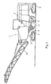
- a road milling machine 1 In Fig. 1, a road milling machine 1 is shown, in which the Fräsrohrschnell hierarchical system described below can be used.
- Road milling machines generally consist of a machine frame 2 on which an internal combustion engine and a control station is mounted.
- the self-propelled road milling machine has height-adjustable, attached to the machine frame 2 lifting columns 3, where support wheels or track assemblies 5 are mounted.
- the milling drum 4 is located under the machine frame 2 in a roller box 11, which is bounded laterally by the side plates 12,13.
- the processed from the milling drum 4 material is dropped in a conventional manner on a first conveyor belt 9 and conveyed to a second, height-adjustable and pivotable conveyor belt 16.
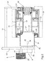
- a milling drum 4 is rotatable between side plates orthogonal to the axis of the milling drum. 12,13 of the roller box 11 and is driven via a mounted on the drive side side plate 12 drive means 6 and a reduction gear 8.
- the milling drum 4 consists of a on a drive-side side plate 12 arranged housing 26 of the reduction gear 8 coupled roller base 14 and a one-piece milling tube 10 which is removably attached to the roller body 14.
- the roll main body 14 is disposed axially adjacent to the reduction gear part 8b.
- the roller base body 14 transmits the torque of the reduction gear 8 to the respective inserted milling tube 10.
- usable milling tubes 10 different milling width and different tooling are available for different roadworks and can be replaced quickly.
- Fig. 2 shows a first embodiment in which the drive means 6 is arranged on the drive-side side plate 12, of which in Fig. 2, only the pulley 35 is shown.
- the internal combustion engine drives this pulley 35, for example via a compound V-belt.
- the pulley 35 is coupled directly to a coupling point 18 with a first reduction stage of the reduction gear 8 in a drive-side gear part 8a.
- a further reduction stage is coupled to the first reduction stage via a transmission shaft 28.
- the second reduction stage is arranged in a preferably circular-cylindrical housing 26 which is arranged on the milling-side side of the drive-side side plate 12.
- the housing 26 forms the output element of the reduction gear. 8
- a roller base 14 is mounted coaxially to the housing 26 by means of an end face provided on the roller body annular flange 15, wherein the free end of the roller body 14 is mounted in a floating bearing in the drive side side plate 12 opposite side plate 13 ,
- the side plate 13 is arranged on the neutral side of the road milling machine, which indicates the side in which a near-edge milling is possible.
- the annular flange 15 of the roller base body 14 has a maximum of the same outer diameter as the cylindrical housing 26, wherein the inner diameter of the annular flange 15 is seated on a cylindrical spigot 27 of the housing 26, so that ensures a precisely coaxial aligned position of the roller body 14 to the reduction gear 8 is.
- a second annular flange 17 is provided on the roller base 14, which serves as a fastening means for the milling tubes 10.
- annular flanges 19 or other fastening means radially inwardly which cooperate with the annular flange 17.
- the annular flange 17 transmits the torque of the roller base body 14 to the milling tube 10.
- the milling tube 10 is equipped, for example, with chisels 22 whose engagement circle 24 in FIGS. is indicated by the dashed line.
- the maximum milling depth FT is indicated by a further dashed line below the side plates 12, 13.
- the easily removable side plate 13 is preferably pivotable, but may alternatively be axially removable.
- the milling tube shown in Fig. 2 has a milling width of 750 mm.
- the drive side facing free end of the milling tube 10 is supported on a support ring 29 which is slid onto the housing 26 and fixed there. From this radial support ring 29 is a fixed to the support ring 29 protective tube 30 from which coaxially surrounds the circular cylindrical housing 26 and the housing 26 of the reduction gear 8 protects against damage. Between the radial support ring 29 and the milling tube 10, a floating bearing is formed, wherein the milling tube 10 can slide on the support ring 29.
- the radial support ring 29 and the protective tube 30 may be secured to the milling tube 10, wherein the common construction of the support ring 29 and the protective tube 30 seated on the housing 26 and on the seat on the parallel to the transmission shaft 28 extending lateral surface 25 of the housing 26 in the type of a floating bearing can slide.
- the roller main body 14 is in the embodiments of FIGS. 2 to 5 with the housing 26 of the reduction gear 8 and pre-assembled with the annular flange 19. If a change of the milling tube 10 due to another task in the milling required, this change can be performed quickly by first the side plate 13 is dismantled or pivoted. Then the glands between the milling tube and the annular flange 19 must be removed, after which the entire milling tube can be deducted from the null side. Subsequently, the radial support ring 29 is withdrawn with the attached thereto support tube 30 from its seat on the housing 26. They can remain on the housing if the milling tube is only exchanged for reasons of wear and a similar milling tube or another type of milling tube of the same milling width, eg for fine milling, is pushed back.
- the assembly is done in reverse order. First, therefore, the support ring 29 is pushed with the attached protective tube 30 to the seat on the lateral surface 25 of the housing 26 and fixed there. Subsequently, the milling tube 10 can be pushed onto the roller base body 14 and the radial support ring 29.
- the milling tube 10 is screwed to the annular flange 19, wherein at the zero side facing the end of the milling tube 10, a further annular flange 33 may be arranged as a front end cover to the front end of the milling tube 10, an ingress of dirt into the interior of the milling tube 10 prevent.
- the support ring 29 may also be integral with the milling tube 10, in which case the milling tube 10 is pushed together with the support ring 29 on the roller body 14. Also, the annular flange 19 may in principle be integral with the milling tube 10.
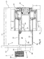
- FIG. 3 largely corresponds to the embodiment of FIG. 2, wherein the milling tube 10 has a maximum milling width between the side plates 12,13.
- the radially supporting annular flange 29 is supported on the drive-side end of the housing 26.
- the attached to the annular flange 29 protective tube 30 is shortened and terminates at the front end of the housing 26, which faces the drive side.
- annular flange 29 are secured to the protective tube 30 to the milling tube 10 and are pushed together with this on the lateral surface 25 of the housing 26.
- the milling tube 10 is even shorter than in the embodiment of FIG. 2, so that a second radial support of the milling tube 10 can be omitted.
- the protective tube 30 is fixed to the annular flange 19 of the milling tube 10.
- the milling tube 10 is pushed together with the protective tube 30 on the seat on the lateral surface 25 of the housing 26.
- FIGS. 2 to 5 when changing the milling width both the reduction gear and the roller main body 14 remain unchanged, while the milling tubes can be mounted or dismounted axially from the neutral side. Access from the drive side is not required.
- FIG. 5 shows a milling tube with a short milling width, which is bolted to the roller base body 14 only via the annular flange 19.
Landscapes
- Engineering & Computer Science (AREA)
- Mechanical Engineering (AREA)
- Mining & Mineral Resources (AREA)
- Architecture (AREA)
- Civil Engineering (AREA)
- Structural Engineering (AREA)
- Road Repair (AREA)
- Milling Processes (AREA)
- Rollers For Roller Conveyors For Transfer (AREA)
- General Details Of Gearings (AREA)
- Pharmaceuticals Containing Other Organic And Inorganic Compounds (AREA)
- Control Of Position, Course, Altitude, Or Attitude Of Moving Bodies (AREA)
- Adjustment And Processing Of Grains (AREA)
- Grinding Of Cylindrical And Plane Surfaces (AREA)
- Road Paving Machines (AREA)
Abstract
Description
Die Erfindung betrifft eine selbstfahrende Straßenfräsmaschine nach dem Oberbegriff des Anspruchs 1.The invention relates to a self-propelled road milling machine according to the preamble of
Häufig ist es nötig, aufgrund unterschiedlicher Baustellensituationen und Fräsarbeiten, das Fräswerkzeug einer Straßenfräsmaschine den spezifischen Aufgaben anzupassen. Beispielsweise, wenn eine bestimmte Oberflächenrauhigkeit erreicht werden soll, ist eine Fräswalze mit einem bestimmten Linienabstand der Fräswerkzeuge oder eine andere Werkzeugausrüstung erforderlich. In einem anderen Anwendungsfall sollen nur bestimmte Fahrbahnbreiten ausgebaut werden, so dass eine Fräswalze mit einer bestimmten Arbeitsbreite benötigt wird.Often it is necessary, due to different construction site situations and milling, to adapt the milling tool of a road milling machine to the specific tasks. For example, if a certain surface roughness is to be achieved, a milling drum with a certain line spacing of the milling tools or other tooling is required. In another application, only certain roadway widths are to be expanded, so that a milling drum with a certain working width is needed.
In der Regel muß in solchen Situationen eine spezielle Fräsmaschine eingesetzt werden, oder die Maschine muß mit einer der Aufgabe angepaßten Fräswalze ausgerüstet werden. Gegenwärtig ist der Austausch der Fräswalzen aber sehr aufwändig und erfordert spezielle Hilfsmittel zur Montage bzw. Demontage der Fräswalze.In general, a special milling machine must be used in such situations, or the machine must be equipped with a task adapted to the milling drum. At the moment, however, the replacement of the milling drums is very complicated and requires special aids for mounting or dismounting the milling drum.
Die Anpassung des Fräswerkzeuges an unterschiedliche Anforderungen ist im Stand der Technik bekannt.The adaptation of the milling tool to different requirements is known in the art.
In der US 4,704,045 wird ein Fräsaggregat beschrieben, dessen Breite durch die Verwendung von verschiedenen Walzensegmenten variiert werden kann. Die Walzensegmente werden bei dieser Lösung über eine Steckverbindung miteinander verbunden. Diese Art stellt in gewisser Weise zwar ein Fräswalzen-Schnellwechselsystem dar, welches aber die folgenden Nachteile besitzt:In US 4,704,045 a milling unit is described, the width of which can be varied by the use of different roller segments. The roller segments are connected to each other in this solution via a plug connection. Although this type is to a certain extent a milling roller quick-change system, it has the following disadvantages:
Unvorteilhaft an dieser Lösung ist, dass der Fräswalzenantrieb hydrostatisch erfolgt, indem auf beiden Seiten der Fräswalze Hydraulikmotoren angebracht werden. Darüber hinaus ist die Verbindung zwischen den Segmenten eine einfache Steckverbindung, die nur eine unzureichende Zentrierung des Fräsrotors erlaubt. Dadurch, dass auf beiden Seiten eine Antriebsvorrichtung vorgesehen ist, ist kein kantennahes Fräsen möglich. Außerdem ist ein Walzengehäuse variabeler Breite erforderlich, das konstruktiv sehr aufwändig ist.A disadvantage of this solution is that the milling drum drive hydrostatically by hydraulic motors are mounted on both sides of the milling drum. In addition, the connection between the segments is a simple connector that allows only insufficient centering of the milling rotor. Characterized in that a drive device is provided on both sides, not close to the edge milling is possible. In addition, a roll housing variable width is required, which is very expensive to construct.
Die US 4,720,207 beschreibt auf einem Walzengrundkörper montierte Fräsrohrsegmente. Bei dieser Konzeption wird zunächst an einer Seite ein Eckringsegment angebracht. Dann werden die Fräsrohrsegmente an diesem verschraubt, wobei die Verschraubungen innerhalb der Segmente sind. Nachteilig ist der enorme Verschraubungsaufwand und, daß die Frästiefe aufgrund des konstanten Durchmessers des Grundkörpers, eingeschränkt ist, wenn ein Planetengetriebe in den Grundkörper integriert ist.US 4,720,207 describes mounted on a roll body Fräsrohrsegmente. In this concept, a corner ring segment is first attached to one side. Then the Fräsrohrsegmente are screwed to this, with the glands are within the segments. A disadvantage is the enormous Verschraubungsaufwand and that the depth of cut is limited due to the constant diameter of the body, when a planetary gear is integrated into the body.
Eine andere Lösung, bei der vor allem die Frästiefe nicht eingeschränkt ist, wird in der US 5,505,598 beschrieben. Das Untersetzungsgetriebe dieser Fräswalze befindet sich auf der der Riemenabtriebsscheibe gegenüberliegenden Seite und wird von einer durch die Fräswalzenachse geführten Antriebswelle angetrieben.Another solution, in which especially the depth of cut is not limited, is described in US 5,505,598. The reduction gear of this milling drum is located on the opposite side of the belt driven pulley and is driven by a guided through the Fräswalzenachse drive shaft.
Diese Getriebeanordnung mit einem Getriebe, dessen Außendurchmesser nur geringfügig geringer ist als der des Fräsrohres, ist erforderlich, um ein bündiges Fräsen zu ermöglichen. Von dem Abschnitt der Fräswalze, in dem das Untersetzungsgetriebe integriert ist, steht ein Achsstumpf ab, auf dem weitere Segmente mit Fräswerkzeugen angebracht werden können.This gear arrangement with a gear whose outer diameter is only slightly smaller than that of the milling tube, is required to allow a flush milling. From the section of the milling drum, in which the reduction gear is integrated, stands out from a stub axle on which more segments can be attached with milling tools.
Nachteilig an dieser Lösung ist, dass zur Durchführung verschiedener Fräsarbeiten, wie Normal- oder Feinfräsen, eine vollständige Demontage der Fräswalze erfolgen muss. Bei einem Arbeitseinsatz mit maximaler Arbeitsbreite, d.h. wenn alle Segmente montiert sind, haben die einzelnen Segmente dann unterschiedliche Schnittkreisdurchmesser, so dass die damit gefräste Straßenoberfläche in Querrichtung stufig gefräst werden.A disadvantage of this solution is that to carry out various milling, such as normal or fine milling, a complete disassembly of the milling drum must be done. In a work application with maximum working width, i. if all segments are mounted, the individual segments then have different cutting circle diameters, so that the milled road surface milled in the transverse direction are staged.
Die drei zuletzt genannten Lösungen haben auch den Nachteil, dass die segmentierten Fräsrohre einem unterschiedlichen Verschleiß unterliegen, da nicht alle Fräsrohrsegmente immer im Einsatz sind.The last three mentioned solutions also have the disadvantage that the segmented milling tubes are subject to different wear, since not all milling tube segments are always in use.
Aus der gattungsgemäßen WO 01/04422 ist eine Straßenfräsmaschine mit einem Maschinenrahmen bekannt, in dem eine Fräswalze drehbar gelagert ist, wobei die Fräswalze einen von einer Fräswalzenantriebseinrichtung über eine Getriebeeinheit angetriebenen Walzengrundkörper und alternativ einsetzbare, koaxiale, auf den Walzengrundkörper einseitig aufschiebbare und auswechselbar befestigte Fräsrohre aufweist, die auf der äußeren Mantelfläche Schneidwerkzeuge tragen.From the generic WO 01/04422 a road milling machine with a machine frame is known, in which a milling drum is rotatably mounted, wherein the milling drum a driven by a Fräswalzenantriebseinrichtung via a gear unit roller body and alternatively usable, coaxial, on one side of the roller body pushed and exchangeable attached milling tubes has, which carry cutting tools on the outer circumferential surface.
Bei der bekannten selbstfahrenden Straßenfräsmaschine ist das Untersetzungsgetriebe im Falle von sich über die gesamte Arbeitsbreite erstreckenden Fräsrohren antriebsseitig vorgesehen. Der Walzengrundkörper ist dabei an einem radial abstehenden Flansch des Getriebegehäuses befestigt, wobei eine Verschraubung von der schlecht zugänglichen Antriebsseite erforderlich ist. Die bekannte Lösung mit der Anordnung des Untersetzungsgetriebes auf der Antriebsseite ist für Fräsrohre geringerer Fräsbreite nicht sinnvoll einsetzbar, weil die Frästiefe aus folgenden Gründen beschränkt ist:In the known self-propelled road milling machine, the reduction gear is provided on the drive side in the case of over the entire working width extending milling tubes. The roller body is attached to a radially projecting flange of the gear housing, with a screw from the poorly accessible drive side is required. The known solution with the arrangement of the reduction gear on the drive side is not useful for milling tubes lesser milling width, because the depth of cut is limited for the following reasons:
Die Fräsrohre müssen nahezu bündig mit der Nullseite abschließen, um ein kantennahes Fräsen zu ermöglichen. Das auf der Antriebsseite angeordnete Getriebe würde die realisierbare Frästiefe begrenzen.The milling tubes must be almost flush with the zero side to allow a near-edge milling. The arranged on the drive side gear would limit the feasible depth of cut.
Bei nicht über die gesamte Arbeitsbreite sich erstreckenden Fräsrohren ist daher das Untersetzungsgetriebe auf der Nullseite der Maschine, d.h. an der Seite, auf der ein kantennahes Fräsen möglich ist, angeordnet.Therefore, with mill tubes not extending over the entire working width, the reduction gear is on the null side of the machine, i. on the side on which a near-edge milling is possible arranged.
Nachteilig ist dabei, dass eine sich von der Antriebsseite bis zum Untersetzungsgetriebe auf der Nullseite erstreckende Antriebswelle erforderlich ist, die gelagert werden muss, und die mit einem zusätzlichen Schutzrohr gegen Beschädigung versehen werden muss. Das Untersetzungsgetriebe bildet ein Festlager, wobei durch die Anordnung auf der Nullseite zwangsläufig auf der Antriebsseite ein Loslager angeordnet sein muss. Dies ist insofern nachteilig, als auf der Nullseite eine verschwenkbare Seitenplatte zum schnellen Wechseln der Fräsrohre angeordnet ist, die weniger geeignet ist, die hohen Reaktionskräfte eines Festlagers in Axialrichtung aufzunehmen. Desweiteren befindet sich bei dieser Lösung das Loslager auf der schlecht zugänglichen Antriebsseite, an der beispielsweise die Verdrehsicherung für das Loslager montierbar sein muss. Ein weiterer Nachteil besteht darin, dass die lange Antriebswelle wie eine Torsionsfederung wirkt, wodurch ein starrer Antrieb der Fräswalze nicht möglich ist und die maximal möglichen Schnittkräfte reduziert werden.The disadvantage here is that extending from the drive side to the reduction gear on the null side drive shaft is required, which must be stored, and must be provided with an additional protection tube against damage. The reduction gear forms a fixed bearing, which must be arranged by the arrangement on the null side inevitably on the drive side a floating bearing. This is disadvantageous in that a pivotable side plate for quick change of the milling tubes is arranged on the null side, which is less suitable to absorb the high reaction forces of a fixed bearing in the axial direction. Furthermore, located in this solution, the floating bearing on the poorly accessible drive side on which, for example, the anti-rotation must be mountable for the floating bearing. Another disadvantage is that the long drive shaft acts as a torsion suspension, whereby a rigid drive of the milling drum is not possible and the maximum possible cutting forces are reduced.
Zum Stützen der Fräsrohre auf dem Walzengrundkörper sind zwingend geteilte Ringe erforderlich, die in einer Zwangslage des Monteurs montiert werden müssen. Die Montage der geteilten Stützringe kann es erforderlich machen, die Drehposition des Walzengrundkörpers wiederholt zu verändern, beispielsweise um 180 °, wodurch Unfallgefahren entstehen.To support the milling tubes on the roller body imperatively divided rings are required, which must be mounted in a predicament of the mechanic. The assembly of the split support rings may make it necessary to repeatedly change the rotational position of the roller body, for example by 180 °, which causes accidents.
Der Erfindung liegt die Aufgabe zugrunde, eine selbstfahrende Straßenfräsmaschine zu schaffen, bei der ein Wechsel von Fräsrohren unterschiedlicher Fräsbreite vereinfacht ist und die dafür benötigte Zeit und der Arbeitsaufwand minimiert ist.The invention has for its object to provide a self-propelled road milling machine, in which a change of milling tubes different milling width is simplified and the time and labor required for it is minimized.
Die Erfindung sieht in vorteilhafter Weise vor, dass das Untersetzungsgetriebe antriebsseitig angeordnet ist, dass das Untersetzungsgetriebe ein innenseitig von der antriebsseitigen Seitenplatte angeordnetes Abtriebselement aufweist, dessen Mantelfläche einen Sitz für von der Nullseite her aufschiebbare Fräsrohrelemente, nämlich die antriebsseitigen Enden der Fräsrohre oder radiale Stützeinrichtungen für die Fräsrohre und/oder rohrförmige Schutzeinrichtungen für das Abtriebselement bildet, und dass der Walzengrundkörper an der freien Stirnseite des Abtriebselementes an das Untersetzungsgetriebe angekoppelt ist, ohne das Aufschieben der Fräsrohrelemente zu behindern.The invention provides in an advantageous manner that the reduction gear is arranged on the drive side, that the reduction gear has an inside of the drive-side side plate arranged output element, the lateral surface a seat for sliding from the null side Fräsrohrelemente, namely the drive-side ends of the milling tubes or radial support means for forms the milling tubes and / or tubular guards for the output element, and that the roller body is coupled to the free end of the output member to the reduction gear, without hindering the sliding of the Fräsrohrelemente.
Gemäß der Erfindung ist das Untersetzungsgetriebe auf der Antriebsseite angeordnet, wobei das Untersetzungsgetriebe ein vorzugsweise kreiszylindrisches Gehäuse aufweist, das das Abtriebselement des Untersetzungsgetriebes bildet, wobei der Walzengrundkörper an der Stirnseite des Gehäuses an das Untersetzungsgetriebe angekoppelt ist. Auf diese Weise ist es möglich, Fräsrohre unterschiedlicher Fräsbreite bis hin zur maximalen Fräsbreite stets von der Nullseite auf den Walzengrundkörper und/oder das Gehäuse aufzuschieben, wobei eine Montage ausschließlich von der Nullseite her erfolgen kann. Das Gehäuse weist eine Querschnittsform auf, die ein Aufschieben des Fräsrohres oder von Stützeinrichtungen für das Fräsrohr und/oder Schutzeinrichtungen für das Gehäuse von der Nullseite zulässt, wobei die Innenkontur der Stützeinrichtungen bzw. der Schutzeinrichtungen der Querschnittsform des Gehäuses angepasst ist. Insofern bildet das Gehäuse einen Sitz für von der Nullseite her aufschiebbare Fräsrohrenden, Stütz- und/oder Schutzeinrichtungen. Der Walzengrundkörper hat hierzu einen maximalen Außendurchmesser, der nicht größer ist als der Außendurchmesser des Gehäuses. Es sind keine geteilten Ringe zum Abstützen der Fräsrohre erforderlich, die nach dem Stand der Technik in einer Zwangslage montiert werden müssen. Die Ankopplung des Walzengrundkörpers an der Stirnseite des Gehäuse erhöht in vorteilhafter Weise die realisierbare Frästiefe. Die einteiligen Stützringe gemäß der Erfindung sind leicht auf das Gehäuse des Untersetzungsgetriebes von der Nullseite her aufschiebbar und dort an beliebiger Stelle in bequemer Weise für den Monteur fixierbar.According to the invention, the reduction gear is arranged on the drive side, wherein the reduction gear has a preferably circular cylindrical housing which forms the output element of the reduction gear, wherein the roller base body is coupled to the reduction gear on the end face of the housing. In this way, it is possible to always postpone milling tubes of different milling width up to the maximum milling width from the null side to the roller main body and / or the housing, wherein assembly can be effected exclusively from the neutral side. The housing has a cross-sectional shape, which allows a sliding of the milling tube or support means for the milling tube and / or protective devices for the housing from the null side, wherein the inner contour of the support means or the protective devices is adapted to the cross-sectional shape of the housing. In this respect, the housing forms a seat for sliding from the null side Fräsrohrenden, support and / or protective devices. The roller body has for this purpose a maximum outer diameter which is not greater than the outer diameter of the housing. There are no split rings for supporting the Fräsrohre required, which must be mounted according to the prior art in a predicament. The coupling of the roller body on the front side of the housing advantageously increases the feasible milling depth. The one-piece support rings according to the invention are easy on the Housing of the reduction gear can be pushed from the null side and fixed there at any point in a convenient way for the fitter.
Dies vereinfacht in erheblichem Umfang den Montageaufwand und die hierfür erforderliche Zeit. Darüber hinaus werden auch Unfallgefahren minimiert, weil auf der schlecht zugänglichen Antriebsseite keine Montagearbeiten ausgeführt werden müssen und ein Drehen der Fräswalze nicht erforderlich ist.This considerably simplifies the installation effort and the time required for this. In addition, accident risks are minimized because on the hard to reach drive side no assembly work must be performed and turning the milling drum is not required.
Das in seiner Querschnittsform den Stützeinrichtungen für das Fräsrohr angepasste kreiszylindrische Gehäuse des Untersetzungsgetriebes kann rohr- oder ringförmige, ungeteilte radiale Stützeinrichtungen für das Fräsrohr und/oder Schutzeinrichtungen für das Gehäuse auf seiner gesamten axialen Länge aufnehmen. Selbstverständlich kann der Sitz für die Stütz- und/oder Schutzeinrichtungen sich auch nur auf einen Teil der axialen Länge des vorzugsweise kreiszylindrischen Gehäuses erstrecken.The circular-cylindrical housing of the reduction gear adapted in its cross-sectional shape to the support means for the milling tube can receive tubular or annular, undivided radial support means for the milling tube and / or protective devices for the housing over its entire axial length. Of course, the seat for the support and / or protective devices may extend only to a part of the axial length of the preferably circular cylindrical housing.
Dabei ist insbesondere vorgesehen, dass die radialen Stützeinrichtungen auf dem vorzugsweise kreiszylindrischen Gehäuse ein Loslager für das Fräsrohr bilden. Die rohr- oder ringförmigen, radialen Stützeinrichtungen umfassen das vorzugsweise kreiszylindrische Gehäuse formschlüssig. Dabei werden in vorteilhafter Weise die Fräsrohre automatisch zentriert, so dass die Gefahr von Unwuchten minimiert ist. Das Loslager kann entweder zwischen dem Fräsrohr und der radialen Stützeinrichtung, z:B. einem radialen Stützring, gebildet sein oder, wenn der radiale Stützring an dem Fräsrohr befestigt ist, zwischen dem radialen Stützring und dem Sitz auf der Mantelfläche des Gehäuse gebildet sein. In diesem Fall können der radiale Stützring und ein eventuell an den radialen Stützring befestigtes Schutzrohr auf der Sitzfläche, nämlich der Mantelfläche des Gehäuses des Untersetzungsgetriebes, gleiten.It is provided in particular that the radial support means form a movable bearing on the preferably circular cylindrical housing for the milling tube. The tubular or annular, radial support means comprise the preferably circular-cylindrical housing in a form-fitting manner. In this case, the milling tubes are automatically centered in an advantageous manner, so that the risk of imbalances is minimized. The floating bearing can either between the milling tube and the radial support means, z. a radial support ring, be formed or, when the radial support ring is fixed to the milling tube, be formed between the radial support ring and the seat on the lateral surface of the housing. In this case, the radial support ring and a possibly attached to the radial support ring protective tube on the seat surface, namely the lateral surface of the housing of the reduction gear, slide.
An der Stirnseite des Gehäuses kann eine Zentriereinrichtung für den Walzengrundkörper angeordnet sein. Die Zentriereinrichtung besteht beispielsweise auf einem Zentrieransatz, der entweder sich auf der inneren Mantelfläche des rohrförmigen Walzengrundkörpers abstützt oder vorzugsweise an den Innendurchmesser eines Anschlussflansches des Walzengrundkörpers angepasst ist.On the front side of the housing may be arranged a centering device for the roller body. The centering device consists for example of a centering approach, which is either supported on the inner circumferential surface of the tubular roller base body or preferably adapted to the inner diameter of a connecting flange of the roller body.
Bei bevorzugten Ausführungsbeispielen ist vorgesehen, dass das freie Ende des Walzengrundkörpers einseitig in der leicht demontierbaren, der antriebsseitigen Seitenplatte gegenüberliegenden Seitenplatte gelagert ist. In diesem Fall ist das auf der Nullseite vorgesehene Lager des Walzengrundkörpers ein Loslager, während antriebsseitig durch das Untersetzungsgetriebe ein Festlager gebildet ist. Der Vorteil besteht darin, dass das axiale Kräfte aufnehmende Festlager auf der starren Antriebsseite angeordnet ist, an der die Seitenplatte höhere Reaktionskräfte insbesondere höhere axiale Reaktionskräfte aufnehmen kann.In preferred embodiments, it is provided that the free end of the roller body is mounted on one side in the easily removable, the drive-side side plate opposite side plate. In this case, the provided on the null side bearing of the roller body is a floating bearing, while the drive side is formed by the reduction gear, a fixed bearing. The advantage is that the axial forces receiving bearing is arranged on the rigid drive side, on which the side plate can accommodate higher reaction forces in particular higher axial reaction forces.
An der radialen Stützeinrichtung für das Fräsrohr kann ein das des Untersetzungsgetriebe übergreifendes Schutzrohr befestigt sein, um das Gehäuse gegen Beschädigung zu schützen.At the radial support means for the milling tube, a protective tube which engages over the reduction gear can be fastened in order to protect the housing against damage.
Bei einer Weiterbildung der Erfindung ist vorgesehen, dass das Untersetzungsgetriebe mindestens eine Untersetzungsstufe in einem antriebsseitigen Getriebeteil an der Kopplungsstelle mit der Antriebseinrichtung und mindestens eine weitere Untersetzungsstufe im Inneren des Fräsrohres in einem fräswalzenseitigen Getriebeteil aufweist.In a development of the invention, it is provided that the reduction gearbox has at least one reduction stage in a drive-side gear part at the coupling point with the drive device and at least one further reduction step inside the milling tube in a milling roller-side gear part.
Die Aufteilung des Untersetzungsgetriebes in ein antriebsseitiges Getriebeteil an der Kopplungsstelle der Antriebseinrichtung und in ein weiteres innerhalb der Fräswalze angeordneten Getriebeteil ermöglicht die Verringerung des Durchmessers des zylindrischen Gehäuseelementes, wodurch bei Fräsrohren kürzerer Baulänge eine grö-βere Frästiefe erzielbar ist.The division of the reduction gear in a drive-side gear part at the coupling point of the drive device and in a further arranged within the milling drum gear part allows the reduction of the diameter of the cylindrical housing element, which in milling tubes of shorter overall length a greater βere milling depth can be achieved.
Vorzugsweise ist vorgesehen, dass die mindestens eine antriebsseitige Untersetzungsstufe axial versetzt zu der mindestens einen fräswalzenseitigen Untersetzungsstufe angeordnet ist.It is preferably provided that the at least one drive-side reduction stage is arranged axially offset from the at least one milling roller-side reduction stage.
Dabei sind die Getriebeteile auf beiden Seiten der antriebsseitigen Seitenplatte angeordnet. Die beiden Getriebeteile sind über eine durch die Seitenplatte hindurchgehende Getriebewelle miteinander gekoppelt.The gear parts are arranged on both sides of the drive-side side plate. The two gear parts are coupled together via a passing through the side plate transmission shaft.
Die auf der Nullseite vorgesehene leicht demontierbare Seitenplatte kann zum Auswechseln der Fräsrohre verschwenkbar gestaltet sein.The provided on the null side easily removable side plate can be designed to swap the milling tubes.
Das vorzugsweise kreiszylindrische Gehäuse weist einen Außendurchmesser von maximal 400 mm, vorzugsweise von maximal 350 mm auf.The preferably circular-cylindrical housing has an outer diameter of at most 400 mm, preferably of at most 350 mm.
Bei einer bevorzugten Ausführungsform ist vorgesehen, dass der Walzengrundkörper einen ersten stirnseitigen Ringflansch aufweist, der axial von der Nullseite her an die Stirnseite des Gehäuses ankoppelbar ist, sowie einen zweiten radial auf den Walzengrundkörper drehfest aufsitzenden Ringflansch aufweist, der axial mit einem von dem Fräsrohr radial nach innen abstehenden Ringflansch koppelbar ist. Das von dem Gehäuses des Untersetzungsgetriebes als Abtriebselement abgegebene Drehmoment wird mit Hilfe des Ringflansches des Walzengrundkörpers und des radialen Ringflansches des Fräsrohrs auf das Fräsrohr übertragen.In a preferred embodiment, it is provided that the roller base body has a first end-side annular flange, which can be coupled axially from the zero side to the front side of the housing, as well as a second radially on the roller body seated rotationally seated annular flange axially with one of the milling tube radially inwardly projecting annular flange can be coupled. The output from the housing of the reduction gear as output element torque is transmitted by means of the annular flange of the roller body and the radial annular flange of the milling tube to the milling tube.
Im folgenden werden unter Bezugnahme auf die Zeichnungen Ausführungsbeispiele der Erfindung näher erläutert.In the following, embodiments of the invention will be explained in more detail with reference to the drawings.
Es zeigen:
- Fig. 1
- eine selbstfahrende Straßenfräsmaschine, und
- Fign. 2 bis 7
- Ausführungsbeispiele der Erfindung mit Fräsrohren unterschiedlicher Fräsbreite.
- Fig. 1
- a self-propelled road milling machine, and
- FIGS. 2 to 7
- Embodiments of the invention with milling tubes of different milling width.
In Fig. 1 ist eine Straßenfräsmaschine 1 dargestellt, in der das nachfolgend beschriebene Fräsrohrschnellwechselsystem eingesetzt werden kann. Straßenfräsen bestehen im allgemeinen aus einem Maschinenrahmen 2, auf dem ein Verbrennungsmotor und ein Fahrstand montiert ist. Die selbstfahrende Straßenfräsmaschine weist höhenverstellbare, an dem Maschinenrahmen 2 befestigte Hubsäulen 3 auf, an denen Stützräder oder Kettenlaufwerke 5 montiert sind.In Fig. 1, a
Die Fräswalze 4 befindet sich unter dem Maschinenrahmen 2 in einem Walzenkasten 11, der seitlich von den Seitenplatten 12,13 begrenzt ist. Das von der Fräswalze 4 abgearbeitete Material wird in an sich bekannter Weise auf ein erstes Förderband 9 abgeworfen und auf ein zweites, höhenverstellbares und schwenkbares Förderband 16 weiterbefördert.The milling
Eine Fräswalze 4 ist drehbar zwischen orthogonal zur Achse der Fräswalze verlaufenden Seitenplatten. 12,13 des Walzenkastens 11 gelagert und wird über eine an der antriebsseitigen Seitenplatte 12 gelagerten Antriebseinrichtung 6 und ein Untersetzungsgetriebe 8 angetrieben.A milling
Die Fräswalze 4 besteht aus einem an ein an der antriebsseitigen Seitenplatte 12 angeordneten Gehäuse 26 des Untersetzungsgetriebes 8 angekoppelten Walzengrundkörper 14 und einem einstückigen Fräsrohr 10, das auswechselbar an dem Walzengrundkörper 14 befestigt ist. Der Walzengrundkörper 14 ist axial neben dem Untersetzungsgetriebeteil 8b angeordnet. Der Walzengrundkörper 14 überträgt das Drehmoment des Untersetzungsgetriebes 8 auf das jeweils eingesetzte Fräsrohr 10. Alternativ einsetzbare Fräsrohre 10 unterschiedlicher Fräsbreite und unterschiedlicher Werkzeugbestückung stehen für unterschiedliche Straßenbearbeitungen zur Verfügung und können schnell ausgewechselt werden.The milling
Fig. 2 zeigt ein erstes Ausführungsbeispiel, bei dem die Antriebseinrichtung 6 an der antriebsseitigen Seitenplatte 12 angeordnet ist, von der in Fig. 2 lediglich die Riemenscheibe 35 gezeigt ist. Der Verbrennungsmotor treibt diese Riemenscheibe 35 beispielsweise über einen Verbundkeilriemen an. Die Riemenscheibe 35 ist direkt an einer Kopplungsstelle 18 mit einer ersten Untersetzungsstufe des Untersetzungsgetriebes 8 in einem antriebsseitigen Getriebeteil 8a gekoppelt. Eine weitere Untersetzungsstufe ist mit der ersten Untersetzungsstufe über eine Getriebewelle 28 gekoppelt. Die zweite Untersetzungsstufe ist in einem vorzugsweise kreiszylindrischen Gehäuse 26 angeordnet, das fräswalzenseitig an der antriebsseitigen Seitenplatte 12 angeordnet ist. Das Gehäuse 26 bildet das Abtriebselement des Untersetzungsgetriebes 8.Fig. 2 shows a first embodiment in which the drive means 6 is arranged on the drive-
An der Stirnseite 23 des kreiszylindrischen Gehäuses 26 ist ein Walzengrundkörper 14 koaxial zu dem Gehäuse 26 mit Hilfe eines an dem Walzengrundkörper stirnseitig vorgesehenen Ringflansches 15 befestigt, wobei das freie Ende des Walzengrundkörpers 14 in einem Loslager in der der antriebsseitigen Seitenplatte 12 gegenüberliegenden Seitenplatte 13 gelagert ist. Die Seitenplatte 13 ist auf der Nullseite der Straßenfräsmaschine angeordnet, die die Seite kennzeichnet, bei der ein kantennahes Fräsen möglich ist. Auf der Nullseite ist der Abstand von der stirnseitigen Kante der Fräswalze 4 zu der Außenwand der Straßenfräsmaschine 1, z.B. die Seitenplatte 13, so gering wie möglich gehalten.On the
Der Ringflansch 15 des Walzengrundkörpers 14 weist maximal den gleichen Außendurchmesser, wie das zylindrische Gehäuse 26 auf, wobei der Innendurchmesser des Ringflansches 15 auf einem zylindrischen Zentrieransatz 27 des Gehäuses 26 aufsitzt, so dass eine exakt koaxial ausgerichtete Lage des Walzengrundkörpers 14 zu dem Untersetzungsgetriebe 8 gewährleistet ist. Mit Abstand von dem Ringflansch 15, sowie mit Abstand von der Seitenplatte 13 ist ein zweiter Ringflansch 17 auf dem Walzengrundkörper 14 vorgesehen, der als Befestigungsmittel für die Fräsrohre 10 dient. Hierzu stehen von der Innenseite der Fräsrohre 10 Ringflansche 19 oder andere Befestigungsmittel radial nach innen ab, die mit dem Ringflansch 17 kooperieren. Der Ringflansch 17 überträgt das Drehmoment des Walzengrundkörpers 14 auf das Fräsrohr 10.The
Das Fräsrohr 10 ist beispielsweise mit Fräsmeißeln 22 bestückt, deren Eingriffskreis 24 in den Fign. durch die gestrichelte Linie angedeutet ist. Die maximale Frästiefe FT ist durch eine weitere gestrichelte Linie unterhalb der Seitenplatten 12,13 angedeutet.The milling
Die leicht demontierbare Seitenplatte 13 ist vorzugsweise schwenkbar, kann aber auch alternativ axial entfernbar sein.The easily
Das in Fig. 2 gezeigte Fräsrohr weist beispielsweise eine Fräsbreite von 750 mm auf. Das der Antriebsseite zugewandte freie Ende des Fräsrohres 10 stützt sich auf einen Stützring 29 auf, der auf das Gehäuse 26 aufgeschoben und dort befestigt ist. Von diesem radialen Stützring 29 steht ein an dem Stützring 29 befestigtes Schutzrohr 30 ab, das koaxial das kreiszylindrische Gehäuse 26 umgibt und das Gehäuse 26 des Untersetzungsgetriebes 8 gegen Beschädigung schützt. Zwischen dem radialen Stützring 29 und dem Fräsrohr 10 ist ein Loslager gebildet, wobei das Fräsrohr 10 auf dem Stützring 29 gleiten kann.The milling tube shown in Fig. 2, for example, has a milling width of 750 mm. The drive side facing free end of the milling
Alternativ kann der radiale Stützring 29 und das Schutzrohr 30 an dem Fräsrohr 10 befestigt sein, wobei die gemeinsame Konstruktion des Stützrings 29 und des Schutzrohrs 30 auf dem Gehäuse 26 aufsitzen und auf dem Sitz auf der parallel zur Getriebewelle 28 verlaufende Mantelfläche 25 des Gehäuses 26 in der Art eines Loslagers gleiten können.Alternatively, the
Der Walzengrundkörper 14 ist bei den Ausführungsbeispielen der Fign. 2 bis 5 mit dem Gehäuse 26 des Untersetzungsgetriebes 8 und mit dem Ringflansch 19 vormontiert. Ist ein Wechsel des Fräsrohres 10 aufgrund einer anderen Aufgabenstellung bei der Fräsbearbeitung erforderlich, kann dieser Wechsel schnell ausgeführt werden, indem zunächst die Seitenplatte 13 demontiert oder verschwenkt wird. Dann müssen die Verschraubungen zwischen dem Fräsrohr und dem Ringflansch 19 entfernt werden, wonach das gesamte Fräsrohr von der Nullseite her abgezogen werden kann. Anschließend wird der radiale Stützring 29 mit dem an diesem befestigten Stützrohr 30 von seinem Sitz auf dem Gehäuse 26 abgezogen. Sie können auf dem Gehäuse verbleiben, wenn das Fräsrohr nur aus Verschleißgründen ausgetauscht wird und ein gleichartiges Fräsrohr oder ein andersartiges Fräsrohr gleicher Fräsbreite, z.B. zum Feinfräsen, wieder aufgeschoben wird.The roller
Bei den Ausführungsbeispielen der Fign. 2 und 3 erfolgt die Montage in umgekehrter Reihenfolge. Zunächst wird demzufolge der Stützring 29 mit dem daran befestigten Schutzrohr 30 auf den Sitz auf der Mantelfläche 25 des Gehäuses 26 aufgeschoben und dort fixiert. Anschließend kann das Fräsrohr 10 auf den Walzengrundkörper 14 und den radialen Stützring 29 aufgeschoben werden.In the embodiments of FIGS. 2 and 3, the assembly is done in reverse order. First, therefore, the
Dann wird das Fräsrohr 10 mit dem Ringflansch 19 verschraubt, wobei an dem der Nullseite zugewandten Ende des Fräsrohres 10 ein weiterer Ringflansch 33 als stirnseitiger Abschlussdeckel angeordnet sein kann, um am stirnseitigen Ende des Fräsrohres 10 ein Eindringen von Schmutz in das Innere des Fräsrohres 10 zu verhindern.Then, the milling
Der Stützring 29 kann auch einstückig mit dem Fräsrohr 10 sein, wobei dann das Fräsrohr 10 gemeinsam mit dem Stützring 29 auf den Walzengrundkörper 14 aufgeschoben wird. Auch der Ringflansch 19 kann grundsätzlich einstückig mit dem Fräsrohr 10 sein.The
Das Ausführungsbeispiel der Fig. 3 entspricht weitgehend dem Ausführungsbeispiel der Fig. 2, wobei das Fräsrohr 10 eine maximale Fräsbreite zwischen den Seitenplatten 12,13 aufweist. Der radial abstützende Ringflansch 29 ist an dem antriebsseitigen Ende des Gehäuses 26 abgestützt. Das an dem Ringflansch 29 befestigte Schutzrohr 30 ist verkürzt und endet an dem stirnseitigen Ende des Gehäuses 26, das der Antriebsseite zugewandt ist.The embodiment of FIG. 3 largely corresponds to the embodiment of FIG. 2, wherein the milling
Alternativ kann bei den Ausführungsbeispielen der Fign. 2 und 3 vorgesehen sein, dass der Ringflansch 29 mit dem Schutzrohr 30 an dem Fräsrohr 10 befestigt sind und gemeinsam mit diesem auf die Mantelfläche 25 des Gehäuses 26 aufgeschoben werden.Alternatively, in the embodiments of FIGS. 2 and 3 be provided that the
Bei dem Ausführungsbeispiel der Fig. 4 ist das Fräsrohr 10 noch kürzer als bei dem Ausführungsbeispiel der Fig. 2, so dass eine zweite radiale Abstützung des Fräsrohrs 10 entfallen kann. In diesem Fall ist das Schutzrohr 30 an dem Ringflansch 19 des Fräsrohres 10 befestigt. Bei der Montage wird das Fräsrohr 10 gemeinsam mit dem Schutzrohr 30 auf den Sitz auf der Mantelfläche 25 des Gehäuses 26 aufgeschoben. Bei den Ausführungsbeispielen der Fign. 2 bis 5 kann bei einem Wechsel der Fräsbreite sowohl das Untersetzungsgetriebe als auch der Walzengrundkörper 14 unverändert bleiben, während die Fräsrohre axial von der Nullseite aus montiert bzw. demontiert werden können. Ein Zugang von der Antriebsseite ist nicht erforderlich.In the embodiment of Fig. 4, the milling
Das Ausführungsbeispiel der Fig. 5 zeigt ein Fräsrohr mit kurzer Fräsbreite, das nur über den Ringflansch 19 mit dem Walzengrundkörper 14 verschraubt ist.The embodiment of FIG. 5 shows a milling tube with a short milling width, which is bolted to the
Besonders vorteilhaft ist, dass bei den Ausführungsbeispielen der Fign. 2 bis 5 jeweils nur das Fräsrohr 10 ausgetauscht werden muss. Das Untersetzungsgetriebe 8 und der Walzengrundkörper bleiben gegenüber der Antriebseinrichtung unverändert, so dass keine Justierung des Antriebsstranges erforderlich ist. Das Fräsrohr 10 wird durch seinen Sitz auf dem Walzengrundkörper 14 und/oder auf dem zylindrischen Gehäuse 26 automatisch zentriert, wodurch insbesondere Unwuchten vermieden werden. Die leicht lösbaren Befestigungseinrichtungen des Fräsrohrs 10 sind vor Verschmutzung und Beschädigung geschützt.It is particularly advantageous that in the embodiments of FIGS. 2 to 5 only the milling
Claims (19)
- Self-propelled road milling machine comprising a machine chassis (2), inside of which a milling roll (4) is rotationally mounted between lateral plates (12,13) that are orthogonal to the axis of the milling roll (4), the milling roll (4), which has a roll base body (14) and a milling tube (10), being adapted to be driven via a drive means (6) which is supported on the exterior of the input-side lateral plate (12) and via a reduction gear unit (8), and the lateral plate (13) situated opposite the input-side lateral plate (12) being easily detachable for exchanging alternatively mountable milling tubes (10) of different milling widths and defining the null side of the machine (1) against which one face of the milling roll (4) abuts in an approximately flush manner to enable a milling that is near to an edge,
characterized in
that the reduction gear unit (8) is mounted on the drive input side,
that the reduction gear unit (8) comprises a drive output element, which is mounted on the interior of the drive input-side lateral plate (12) and whose shell surface (25) forms a seat for milling tube elements that can be slid thereon from the null side, and
that the roll base body (14) is coupled to the reduction gear unit (8) at the free front face (23) of the drive output element without hindering the milling tube elements in being slid on. - Self-propelled road milling machine according to claim 1, characterized in that the milling tube elements consist of the ends of the milling tubes (10) directed to the drive input side or of the radial supporting means for the milling tubes (10) and/or tubular protection means for the output element.
- Self-propelled road milling machine according to claim 2, characterized in that the milling tubes (10) and/or the radial supporting means for the milling tubes (10) and/or the tubular protection means are integrally formed.
- Self-propelled road milling machine according to claim 1 to 3, characterized in that the drive output element has a circularly cylindrical cross-sectional shape.
- Self-propelled road milling machine according to one of claims 1 to 4, characterized in that the drive output element consists of a housing (26) of the reduction gear unit (8).
- Self-propelled road milling machine according to one of claims 1 to 5, characterized in that the roll base body (14) has a maximum outer diameter that is not greater than the outer diameter of the output element (26).
- Self-propelled road milling machine according to one of claims 1 to 6, characterized in that the output element is able to receive tubular or annular radial supporting and/or protection means on at least a part of the entire axial length.
- Self-propelled road milling machine according to one of claims 1 to 7, characterized in that the radial supporting means form a movable bearing for the milling tube (10) on the output element (26).
- Self-propelled road milling machine according to one of claims 1 to 8, characterized in that a centering means (27) for the roll base body (14) is arranged at the face side of the housing (26).
- Self-propelled road milling machine according to one of claims 1 to 9, characterized in that the free end of the roll base body (14) is supported in the easily dismountable lateral plate (13) on one side opposite the input-side lateral plate (12).
- Self-propelled road milling machine according to one of claims 1 to 10, characterized in that a protection tube (30) covering the output element is mounted to the radial supporting means (29) for the milling tube (10) as a protection means.
- Self-propelled road milling machine according to one of claims 5 to 10, characterized in that the housing (26) serving as the output element has an outer diameter of 400 mm at maximum, preferably of 350 mm at maximum.
- Self-propelled road milling machine according to one of claims 1 to 12, characterized in that the roll base body (14) comprises a first face-side annular flange (15) being adapted to be axially coupled to the face of the drive output element (26) from the null side as well as a second annular flange (17) radially seated on the roll base body (14) for rotation therewith, which is adapted to be axially coupled with a supporting means (19) projecting radially inward from the milling tube (10).
- Self-propelled road milling machine according to one of claims 1 to 13, characterized in that a radial supporting ring (29) is arranged as a supporting means for the milling tube (10) at the face-side end of the milling tube (10) and is coaxially seated with a positive fit on the drive output element (26).
- Self-propelled road milling machine according to one of claims 1 to 14, characterized in that the reduction gear unit (8) comprises at least one reduction stage in an input-side gear unit portion (8a) at the site of coupling (18) to the drive means (6) and at least one further reduction stage in a milling roll-side gear unit portion (8b) surrounded by the housing (26).
- Self-propelled road milling machine according to claim 15, characterized in that the at least one input-side reduction unit is arranged so as to be axially offset with respect to the at least one milling roll-side reduction stage.
- Self-propelled road milling machine according to one of claims 15 or 16, characterized in that the at least one input-side reduction stage is arranged on the side of the input-side lateral plate (12) of the machine chassis (2), which is opposite to the milling roll (4).
- Self-propelled road milling machine according to one of claims 15 to 17, characterized in that the at least one input-side reduction stage is coupled with the at least one further reduction stage via a gear shaft (28).
- Self-propelled road milling machine according to one of claims 1 to 18, characterized in that the easily dismountable lateral plate (13) is pivotable to change the milling tubes (10).
Applications Claiming Priority (5)
| Application Number | Priority Date | Filing Date | Title |
|---|---|---|---|
| DE10230784 | 2002-07-09 | ||
| DE10230784 | 2002-07-09 | ||
| DE10232489 | 2002-07-18 | ||
| DE10232489A DE10232489A1 (en) | 2002-07-09 | 2002-07-18 | Self-propelled road milling machine |
| PCT/EP2003/004517 WO2004005623A1 (en) | 2002-07-09 | 2003-04-30 | Self-propelled road milling machine |
Publications (2)
| Publication Number | Publication Date |
|---|---|
| EP1520076A1 EP1520076A1 (en) | 2005-04-06 |
| EP1520076B1 true EP1520076B1 (en) | 2006-01-18 |
Family
ID=30116618
Family Applications (1)
| Application Number | Title | Priority Date | Filing Date |
|---|---|---|---|
| EP03720545A Expired - Lifetime EP1520076B1 (en) | 2002-07-09 | 2003-04-30 | Self-propelled road milling machine |
Country Status (14)
| Country | Link |
|---|---|
| US (1) | US7144192B2 (en) |
| EP (1) | EP1520076B1 (en) |
| JP (1) | JP4190494B2 (en) |
| KR (1) | KR101005186B1 (en) |
| CN (1) | CN100365212C (en) |
| AT (1) | ATE316169T1 (en) |
| AU (1) | AU2003224140B2 (en) |
| BR (1) | BR0311553B1 (en) |
| CA (1) | CA2481779C (en) |
| DE (1) | DE50302240D1 (en) |
| ES (1) | ES2255672T3 (en) |
| MX (1) | MXPA04012008A (en) |
| RU (1) | RU2308561C2 (en) |
| WO (1) | WO2004005623A1 (en) |
Cited By (3)
| Publication number | Priority date | Publication date | Assignee | Title |
|---|---|---|---|---|
| DE102006015506B3 (en) * | 2006-03-31 | 2007-11-08 | Wirtgen Gmbh | Milling roller for a construction machine, construction machine and gear unit for a milling drum |
| WO2010003436A1 (en) * | 2008-07-09 | 2010-01-14 | Marini S.P.A. | Road milling machine with replaceable milling drum for different cutting widths |
| DE102009059064A1 (en) * | 2009-12-18 | 2011-06-22 | Wirtgen GmbH, 53578 | Self-propelled road milling machine |
Families Citing this family (33)
| Publication number | Priority date | Publication date | Assignee | Title |
|---|---|---|---|---|
| DE102006062129B4 (en) | 2006-12-22 | 2010-08-05 | Wirtgen Gmbh | Road construction machine and method for measuring the cutting depth |
| DE102007019202B4 (en) * | 2007-04-20 | 2015-05-21 | Wirtgen Gmbh | Self-propelled construction machine, in particular road milling machine, recycler or stabilizer |
| USD626573S1 (en) * | 2007-08-14 | 2010-11-02 | Wirtgen Gmbh | Road milling machine |
| US8469456B2 (en) | 2009-03-25 | 2013-06-25 | Wirtgen Gmbh | Ejector unit for a road milling machine or the like |
| DE102009014730B3 (en) * | 2009-03-25 | 2010-10-28 | Wirtgen Gmbh | Ejector or ejector unit for a road milling machine or the like |
| US8523289B2 (en) | 2009-04-10 | 2013-09-03 | Kennametal Inc. | Retention assembly for cutting bit |
| US8523290B2 (en) * | 2009-04-10 | 2013-09-03 | Kennametal Inc. | Rotatable cutting tool-tool holder-base assembly |
| USD635160S1 (en) * | 2010-03-19 | 2011-03-29 | Wirtgen Gmbh | Body panels for a construction machine |
| USD660876S1 (en) * | 2010-08-09 | 2012-05-29 | Joseph Vögele AG | Feeder for a road paving machine |
| USD642599S1 (en) | 2010-10-12 | 2011-08-02 | Wirtgen Gmbh | Body panels for a construction machine |
| USD650396S1 (en) | 2010-11-03 | 2011-12-13 | Joseph Vogele Ag | Feeder for a road paving machine |
| US8256847B2 (en) * | 2010-11-30 | 2012-09-04 | Hall David R | Rotational milling chamber |
| DE102011108016A1 (en) * | 2011-07-19 | 2013-01-24 | Liebherr-Components Biberach Gmbh | Self-propelled surface milling cutter |
| US8714660B2 (en) * | 2012-07-16 | 2014-05-06 | Caterpillar Paving Products Inc. | Chamber for milling machine |
| DE102013208645B4 (en) * | 2013-05-10 | 2018-01-11 | Wirtgen Gmbh | Device, in particular small milling machine, for processing road surfaces |
| DE102013013304A1 (en) * | 2013-08-12 | 2015-02-12 | Wirtgen Gmbh | Self-propelled construction machine for machining lanes or ground surfaces and method for cooling the milling tools of a milling drum of a self-propelled construction machine |
| USD774561S1 (en) * | 2014-01-24 | 2016-12-20 | Bomag Gmbh | Cold milling machine |
| USD774562S1 (en) * | 2014-07-22 | 2016-12-20 | Bomag Gmbh | Cold milling machine |
| USD755859S1 (en) * | 2014-08-12 | 2016-05-10 | Bomag Gmbh | Milling machine |
| CN105178145B (en) * | 2015-09-07 | 2018-01-12 | 南陵旺科知识产权运营有限公司 | A kind of light adjustable die mould voluntarily enters the device that rolls over a road |
| DE102017208775A1 (en) * | 2017-05-23 | 2018-11-29 | Wirtgen Gmbh | Soil cultivation machine whose working device with an on-board actuator from its operating position is displaced |
| EP3406798B1 (en) * | 2017-05-23 | 2019-11-20 | Wirtgen GmbH | Replaceable milling roller |
| US10787775B2 (en) * | 2017-07-21 | 2020-09-29 | Roadtec, Inc. | Auxiliary drum drive assembly for milling machine |
| US10577759B2 (en) * | 2017-07-21 | 2020-03-03 | Roadtec, Inc. | Drive belt disengagement for cutter drum of milling machine and auxiliary drum drive assembly |
| USD866618S1 (en) * | 2018-03-16 | 2019-11-12 | Wirtgen Gmbh | Body panels for a road milling machine |
| CN109112930B (en) * | 2018-07-25 | 2020-11-20 | 温州澳鼎建材有限公司 | A special sprinkler roller for road construction |
| KR102259506B1 (en) | 2019-10-15 | 2021-06-02 | 한국도로공사 | Apparatus for removing dust in road milling machine |
| DE102020111311B4 (en) * | 2020-04-24 | 2023-07-27 | Wirtgen Gmbh | Interchangeable unit for texturing soil surface treatment and road construction machine with such an interchangeable unit |
| IT202000013528A1 (en) | 2020-06-08 | 2021-12-08 | Seppi M S P A | MACHINE WITH A CYLINDRICAL HOLLOW TOOL HOLDER ROTOR |
| US11674273B2 (en) | 2021-10-06 | 2023-06-13 | Caterpillar Paving Products Inc. | Milling drum with alignment interface |
| US12486626B2 (en) | 2023-07-19 | 2025-12-02 | Caterpillar Paving Products Inc. | Quick change rotor alignment feature |
| USD1062803S1 (en) * | 2023-10-25 | 2025-02-18 | Hunan Sany Zhongyi Machinery Co., Ltd. | Pavement milling machine |
| USD1061626S1 (en) * | 2024-03-20 | 2025-02-11 | Hunan Sany Zhongyi Machinery Co., Ltd. | Pavement milling machine |
Family Cites Families (16)
| Publication number | Priority date | Publication date | Assignee | Title |
|---|---|---|---|---|
| US3072391A (en) * | 1960-06-21 | 1963-01-08 | James F Mcdarrah | Disintegrating machine having cutting and impact action |
| DE3249844C2 (en) * | 1982-04-15 | 1989-03-09 | Alfred Dr. 2095 Obermarschacht De Hackmack | Attachment device for treating road coverings |
| GB2128540B (en) * | 1982-09-04 | 1986-05-21 | Reinhard Wirtgen | Roughening road surfaces |
| US4704045A (en) * | 1985-10-11 | 1987-11-03 | Taylor Thomas M | Apparatus and method for pulverizing asphalt |
| SU1395727A1 (en) * | 1986-05-06 | 1988-05-15 | Проектно-конструкторское бюро Академии коммунального хозяйства им.К.Д.Памфилова | Apparatus for milling road pavings |
| US4720207A (en) | 1986-08-29 | 1988-01-19 | Koehring Company | Segmented rotor |
| DE4037448B4 (en) * | 1990-11-24 | 2005-09-29 | Wirtgen Gmbh | Milling device for road milling machines |
| US5395417A (en) * | 1993-01-26 | 1995-03-07 | Double T Equipment Manufacturing Ltd. | Apparatus and process used in working windrowed ingredients to produce pre-wet cycle mushroom compost |
| RU2064994C1 (en) * | 1994-01-31 | 1996-08-10 | Михайлов Валентин Васильевич | Road pavement breaking machine |
| US5505598A (en) * | 1994-07-29 | 1996-04-09 | Wirtgen America, Inc. | Milling machine with multi-width cutter |
| DE19504495A1 (en) * | 1995-02-12 | 1996-08-22 | Wirtgen Gmbh | Road surface renewal machine |
| DE19932396A1 (en) | 1999-07-14 | 2001-02-01 | Wirtgen Gmbh | Construction machine and milling drum |
| US6210071B1 (en) * | 1999-09-27 | 2001-04-03 | Astec Industries, Inc. | Method and apparatus for cutting rumble strips in a roadway |
| KR100402150B1 (en) | 2000-09-21 | 2003-10-17 | 유옥경 | Plane cutting machine of Oil Pressure going up and down system |
| RU19656U1 (en) * | 2001-02-02 | 2001-09-20 | Сибирский научно-исследовательский институт строительного и дорожного машиностроения | ROAD MILL |
| US6547484B2 (en) * | 2001-02-14 | 2003-04-15 | Dustrol, Inc. | Apparatus for cutting rumble strips in a road surface |
-
2003
- 2003-04-30 WO PCT/EP2003/004517 patent/WO2004005623A1/en not_active Ceased
- 2003-04-30 AU AU2003224140A patent/AU2003224140B2/en not_active Ceased
- 2003-04-30 US US10/511,031 patent/US7144192B2/en not_active Expired - Lifetime
- 2003-04-30 CN CNB038135701A patent/CN100365212C/en not_active Expired - Fee Related
- 2003-04-30 DE DE50302240T patent/DE50302240D1/en not_active Expired - Lifetime
- 2003-04-30 ES ES03720545T patent/ES2255672T3/en not_active Expired - Lifetime
- 2003-04-30 AT AT03720545T patent/ATE316169T1/en active
- 2003-04-30 BR BRPI0311553-4B1A patent/BR0311553B1/en not_active IP Right Cessation
- 2003-04-30 MX MXPA04012008A patent/MXPA04012008A/en active IP Right Grant
- 2003-04-30 JP JP2004518491A patent/JP4190494B2/en not_active Expired - Fee Related
- 2003-04-30 KR KR1020047020322A patent/KR101005186B1/en not_active Expired - Fee Related
- 2003-04-30 CA CA002481779A patent/CA2481779C/en not_active Expired - Fee Related
- 2003-04-30 EP EP03720545A patent/EP1520076B1/en not_active Expired - Lifetime
- 2003-04-30 RU RU2005103231/03A patent/RU2308561C2/en active
Cited By (8)
| Publication number | Priority date | Publication date | Assignee | Title |
|---|---|---|---|---|
| DE102006015506B3 (en) * | 2006-03-31 | 2007-11-08 | Wirtgen Gmbh | Milling roller for a construction machine, construction machine and gear unit for a milling drum |
| RU2345192C1 (en) * | 2006-03-31 | 2009-01-27 | Виртген Гмбх | Construction machine crushing drum, construction machine proper and crushing drum gearbox |
| US7901011B2 (en) | 2006-03-31 | 2011-03-08 | Wirtgen Gmbh | Milling drum for a construction machine, construction machine as well as gearbox unit for a milling drum |
| US8118369B2 (en) | 2006-03-31 | 2012-02-21 | Wirtgen Gmbh | Milling drum for a construction machine, construction machine as well as gearbox unit for a milling drum |
| WO2010003436A1 (en) * | 2008-07-09 | 2010-01-14 | Marini S.P.A. | Road milling machine with replaceable milling drum for different cutting widths |
| US8474919B2 (en) | 2008-07-09 | 2013-07-02 | Marini S.P.A. | Road milling machine with replaceable milling drum with different cutting widths |
| DE102009059064A1 (en) * | 2009-12-18 | 2011-06-22 | Wirtgen GmbH, 53578 | Self-propelled road milling machine |
| DE102009059064B4 (en) * | 2009-12-18 | 2012-04-26 | Wirtgen Gmbh | Self-propelled road milling machine |
Also Published As
| Publication number | Publication date |
|---|---|
| RU2308561C2 (en) | 2007-10-20 |
| KR20050024333A (en) | 2005-03-10 |
| BR0311553A (en) | 2005-04-12 |
| KR101005186B1 (en) | 2011-01-04 |
| US7144192B2 (en) | 2006-12-05 |
| ATE316169T1 (en) | 2006-02-15 |
| CA2481779C (en) | 2009-07-28 |
| AU2003224140B2 (en) | 2008-05-08 |
| BR0311553B1 (en) | 2013-08-13 |
| ES2255672T3 (en) | 2006-07-01 |
| RU2005103231A (en) | 2005-10-27 |
| MXPA04012008A (en) | 2005-03-07 |
| JP4190494B2 (en) | 2008-12-03 |
| CN1659341A (en) | 2005-08-24 |
| CA2481779A1 (en) | 2004-01-15 |
| US20050158120A1 (en) | 2005-07-21 |
| AU2003224140A1 (en) | 2004-01-23 |
| HK1076134A1 (en) | 2006-01-06 |
| CN100365212C (en) | 2008-01-30 |
| EP1520076A1 (en) | 2005-04-06 |
| DE50302240D1 (en) | 2006-04-06 |
| JP2005532488A (en) | 2005-10-27 |
| WO2004005623A1 (en) | 2004-01-15 |
Similar Documents
| Publication | Publication Date | Title |
|---|---|---|
| EP1520076B1 (en) | Self-propelled road milling machine | |
| EP1194651B1 (en) | Construction machine and milling roller | |
| EP2336426B1 (en) | Self-propelled street milling machine | |
| DE102006015506B3 (en) | Milling roller for a construction machine, construction machine and gear unit for a milling drum | |
| EP2255923B1 (en) | Rotary table | |
| DE2822686C2 (en) | ||
| DE102012008252B4 (en) | Milling attachment for a soil milling machine, milling drum for such a milling attachment, and soil milling machine with such a milling attachment | |
| EP2492071B1 (en) | Milling motor with multiple spindles | |
| EP3872261B1 (en) | Soil working machine and support structure with positive connection between rotating working assembly and its rotary bearing | |
| DE69824509T2 (en) | rolling mill | |
| DE3225235C2 (en) | ||
| EP4161702B1 (en) | Dual-shaft shredder with a horizontal maintenance concept | |
| EP3775535B1 (en) | Large rolling bearing | |
| DE3877380T2 (en) | ROLLING MILLS. | |
| EP2801666B1 (en) | Road milling machine, in particular small milling cutter, for machining of road surfaces | |
| DE10232489A1 (en) | Self-propelled road milling machine | |
| DE19539249A1 (en) | Rotary tool for digging trenches | |
| DE68908678T2 (en) | Machine with at least two driven shafts, especially heavy duty twin screw extruders. | |
| DE69106692T2 (en) | Roll and roll stand. | |
| DE3729470C2 (en) | ||
| WO2022218719A1 (en) | Slurry wall cutter and method for changing a cutting width of a slurry wall cutter | |
| DE102004025567A1 (en) | Device for removing a road surface comprises a cutting roller that can be exchanged together with part of a side wall and optionally the transmission of a cutting roller drive as one unit | |
| EP0038320B1 (en) | A driving roller stand for continuous casting plants | |
| EP1256398B1 (en) | Cross rolling mill | |
| EP1066890A1 (en) | Arrangement for changing the nut securing a rolling ring |
Legal Events
| Date | Code | Title | Description |
|---|---|---|---|
| PUAI | Public reference made under article 153(3) epc to a published international application that has entered the european phase |
Free format text: ORIGINAL CODE: 0009012 |
|
| 17P | Request for examination filed |
Effective date: 20040721 |
|
| AK | Designated contracting states |
Kind code of ref document: A1 Designated state(s): AT BE BG CH CY CZ DE DK EE ES FI FR GB GR HU IE IT LI LU MC NL PT RO SE SI SK TR |
|
| AX | Request for extension of the european patent |
Extension state: AL LT LV MK |
|
| GRAP | Despatch of communication of intention to grant a patent |
Free format text: ORIGINAL CODE: EPIDOSNIGR1 |
|
| GRAS | Grant fee paid |
Free format text: ORIGINAL CODE: EPIDOSNIGR3 |
|
| DAX | Request for extension of the european patent (deleted) | ||
| GRAA | (expected) grant |
Free format text: ORIGINAL CODE: 0009210 |
|
| REG | Reference to a national code |
Ref country code: HK Ref legal event code: DE Ref document number: 1076134 Country of ref document: HK |
|
| AK | Designated contracting states |
Kind code of ref document: B1 Designated state(s): AT BE BG CH CY CZ DE DK EE ES FI FR GB GR HU IE IT LI LU MC NL PT RO SE SI SK TR |
|
| PG25 | Lapsed in a contracting state [announced via postgrant information from national office to epo] |
Ref country code: IE Free format text: LAPSE BECAUSE OF FAILURE TO SUBMIT A TRANSLATION OF THE DESCRIPTION OR TO PAY THE FEE WITHIN THE PRESCRIBED TIME-LIMIT Effective date: 20060118 Ref country code: FI Free format text: LAPSE BECAUSE OF FAILURE TO SUBMIT A TRANSLATION OF THE DESCRIPTION OR TO PAY THE FEE WITHIN THE PRESCRIBED TIME-LIMIT Effective date: 20060118 Ref country code: SI Free format text: LAPSE BECAUSE OF FAILURE TO SUBMIT A TRANSLATION OF THE DESCRIPTION OR TO PAY THE FEE WITHIN THE PRESCRIBED TIME-LIMIT Effective date: 20060118 Ref country code: SK Free format text: LAPSE BECAUSE OF FAILURE TO SUBMIT A TRANSLATION OF THE DESCRIPTION OR TO PAY THE FEE WITHIN THE PRESCRIBED TIME-LIMIT Effective date: 20060118 Ref country code: RO Free format text: LAPSE BECAUSE OF FAILURE TO SUBMIT A TRANSLATION OF THE DESCRIPTION OR TO PAY THE FEE WITHIN THE PRESCRIBED TIME-LIMIT Effective date: 20060118 |
|
| REG | Reference to a national code |
Ref country code: GB Ref legal event code: FG4D Free format text: NOT ENGLISH |
|
| REG | Reference to a national code |
Ref country code: CH Ref legal event code: NV Representative=s name: ISLER & PEDRAZZINI AG Ref country code: CH Ref legal event code: EP |
|
| GBT | Gb: translation of ep patent filed (gb section 77(6)(a)/1977) |
Effective date: 20060118 |
|
| REG | Reference to a national code |
Ref country code: IE Ref legal event code: FG4D Free format text: LANGUAGE OF EP DOCUMENT: GERMAN |
|
| REF | Corresponds to: |
Ref document number: 50302240 Country of ref document: DE Date of ref document: 20060406 Kind code of ref document: P |
|
| PG25 | Lapsed in a contracting state [announced via postgrant information from national office to epo] |
Ref country code: SE Free format text: LAPSE BECAUSE OF FAILURE TO SUBMIT A TRANSLATION OF THE DESCRIPTION OR TO PAY THE FEE WITHIN THE PRESCRIBED TIME-LIMIT Effective date: 20060418 Ref country code: DK Free format text: LAPSE BECAUSE OF FAILURE TO SUBMIT A TRANSLATION OF THE DESCRIPTION OR TO PAY THE FEE WITHIN THE PRESCRIBED TIME-LIMIT Effective date: 20060418 Ref country code: BG Free format text: LAPSE BECAUSE OF FAILURE TO SUBMIT A TRANSLATION OF THE DESCRIPTION OR TO PAY THE FEE WITHIN THE PRESCRIBED TIME-LIMIT Effective date: 20060418 |
|
| PG25 | Lapsed in a contracting state [announced via postgrant information from national office to epo] |
Ref country code: MC Free format text: LAPSE BECAUSE OF NON-PAYMENT OF DUE FEES Effective date: 20060430 |
|
| REG | Reference to a national code |
Ref country code: HK Ref legal event code: GR Ref document number: 1076134 Country of ref document: HK |
|
| PG25 | Lapsed in a contracting state [announced via postgrant information from national office to epo] |
Ref country code: PT Free format text: LAPSE BECAUSE OF FAILURE TO SUBMIT A TRANSLATION OF THE DESCRIPTION OR TO PAY THE FEE WITHIN THE PRESCRIBED TIME-LIMIT Effective date: 20060619 |
|
| REG | Reference to a national code |
Ref country code: ES Ref legal event code: FG2A Ref document number: 2255672 Country of ref document: ES Kind code of ref document: T3 |
|
| REG | Reference to a national code |
Ref country code: IE Ref legal event code: FD4D |
|
| ET | Fr: translation filed | ||
| PLBE | No opposition filed within time limit |
Free format text: ORIGINAL CODE: 0009261 |
|
| STAA | Information on the status of an ep patent application or granted ep patent |
Free format text: STATUS: NO OPPOSITION FILED WITHIN TIME LIMIT |
|
| 26N | No opposition filed |
Effective date: 20061019 |
|
| REG | Reference to a national code |
Ref country code: CH Ref legal event code: PCAR Free format text: ISLER & PEDRAZZINI AG;POSTFACH 1772;8027 ZUERICH (CH) |
|
| PG25 | Lapsed in a contracting state [announced via postgrant information from national office to epo] |
Ref country code: CZ Free format text: LAPSE BECAUSE OF FAILURE TO SUBMIT A TRANSLATION OF THE DESCRIPTION OR TO PAY THE FEE WITHIN THE PRESCRIBED TIME-LIMIT Effective date: 20060118 Ref country code: GR Free format text: LAPSE BECAUSE OF FAILURE TO SUBMIT A TRANSLATION OF THE DESCRIPTION OR TO PAY THE FEE WITHIN THE PRESCRIBED TIME-LIMIT Effective date: 20060419 |
|
| PG25 | Lapsed in a contracting state [announced via postgrant information from national office to epo] |
Ref country code: EE Free format text: LAPSE BECAUSE OF FAILURE TO SUBMIT A TRANSLATION OF THE DESCRIPTION OR TO PAY THE FEE WITHIN THE PRESCRIBED TIME-LIMIT Effective date: 20060118 |
|
| PG25 | Lapsed in a contracting state [announced via postgrant information from national office to epo] |
Ref country code: HU Free format text: LAPSE BECAUSE OF FAILURE TO SUBMIT A TRANSLATION OF THE DESCRIPTION OR TO PAY THE FEE WITHIN THE PRESCRIBED TIME-LIMIT Effective date: 20060719 Ref country code: TR Free format text: LAPSE BECAUSE OF FAILURE TO SUBMIT A TRANSLATION OF THE DESCRIPTION OR TO PAY THE FEE WITHIN THE PRESCRIBED TIME-LIMIT Effective date: 20060118 Ref country code: LU Free format text: LAPSE BECAUSE OF NON-PAYMENT OF DUE FEES Effective date: 20060430 |
|
| PG25 | Lapsed in a contracting state [announced via postgrant information from national office to epo] |
Ref country code: CY Free format text: LAPSE BECAUSE OF FAILURE TO SUBMIT A TRANSLATION OF THE DESCRIPTION OR TO PAY THE FEE WITHIN THE PRESCRIBED TIME-LIMIT Effective date: 20060118 |
|
| REG | Reference to a national code |
Ref country code: FR Ref legal event code: PLFP Year of fee payment: 13 |
|
| REG | Reference to a national code |
Ref country code: FR Ref legal event code: PLFP Year of fee payment: 14 |
|
| REG | Reference to a national code |
Ref country code: FR Ref legal event code: PLFP Year of fee payment: 15 |
|
| REG | Reference to a national code |
Ref country code: FR Ref legal event code: PLFP Year of fee payment: 16 |
|
| PGFP | Annual fee paid to national office [announced via postgrant information from national office to epo] |
Ref country code: FR Payment date: 20200421 Year of fee payment: 18 Ref country code: CH Payment date: 20200423 Year of fee payment: 18 Ref country code: NL Payment date: 20200420 Year of fee payment: 18 Ref country code: ES Payment date: 20200516 Year of fee payment: 18 |
|
| PGFP | Annual fee paid to national office [announced via postgrant information from national office to epo] |
Ref country code: GB Payment date: 20200423 Year of fee payment: 18 Ref country code: BE Payment date: 20200420 Year of fee payment: 18 |
|
| PGFP | Annual fee paid to national office [announced via postgrant information from national office to epo] |
Ref country code: AT Payment date: 20200421 Year of fee payment: 18 |
|
| REG | Reference to a national code |
Ref country code: NL Ref legal event code: MM Effective date: 20210501 |
|
| REG | Reference to a national code |
Ref country code: AT Ref legal event code: MM01 Ref document number: 316169 Country of ref document: AT Kind code of ref document: T Effective date: 20210430 |
|
| GBPC | Gb: european patent ceased through non-payment of renewal fee |
Effective date: 20210430 |
|
| REG | Reference to a national code |
Ref country code: BE Ref legal event code: MM Effective date: 20210430 |
|
| PG25 | Lapsed in a contracting state [announced via postgrant information from national office to epo] |
Ref country code: CH Free format text: LAPSE BECAUSE OF NON-PAYMENT OF DUE FEES Effective date: 20210430 Ref country code: AT Free format text: LAPSE BECAUSE OF NON-PAYMENT OF DUE FEES Effective date: 20210430 Ref country code: LI Free format text: LAPSE BECAUSE OF NON-PAYMENT OF DUE FEES Effective date: 20210430 Ref country code: GB Free format text: LAPSE BECAUSE OF NON-PAYMENT OF DUE FEES Effective date: 20210430 Ref country code: FR Free format text: LAPSE BECAUSE OF NON-PAYMENT OF DUE FEES Effective date: 20210430 |
|
| PG25 | Lapsed in a contracting state [announced via postgrant information from national office to epo] |
Ref country code: NL Free format text: LAPSE BECAUSE OF NON-PAYMENT OF DUE FEES Effective date: 20210501 |
|
| REG | Reference to a national code |
Ref country code: ES Ref legal event code: FD2A Effective date: 20220705 |
|
| PG25 | Lapsed in a contracting state [announced via postgrant information from national office to epo] |
Ref country code: ES Free format text: LAPSE BECAUSE OF NON-PAYMENT OF DUE FEES Effective date: 20210501 Ref country code: BE Free format text: LAPSE BECAUSE OF NON-PAYMENT OF DUE FEES Effective date: 20210430 |
|
| PGFP | Annual fee paid to national office [announced via postgrant information from national office to epo] |
Ref country code: IT Payment date: 20220429 Year of fee payment: 20 Ref country code: DE Payment date: 20220419 Year of fee payment: 20 |
|
| REG | Reference to a national code |
Ref country code: DE Ref legal event code: R071 Ref document number: 50302240 Country of ref document: DE |
|
| P01 | Opt-out of the competence of the unified patent court (upc) registered |
Effective date: 20230525 |