EP1519501A2 - Fibre optique pour des performances améliorées dans les bandes S, C et L - Google Patents
Fibre optique pour des performances améliorées dans les bandes S, C et L Download PDFInfo
- Publication number
- EP1519501A2 EP1519501A2 EP20040022110 EP04022110A EP1519501A2 EP 1519501 A2 EP1519501 A2 EP 1519501A2 EP 20040022110 EP20040022110 EP 20040022110 EP 04022110 A EP04022110 A EP 04022110A EP 1519501 A2 EP1519501 A2 EP 1519501A2
- Authority
- EP
- European Patent Office
- Prior art keywords
- region
- raman
- fiber
- core
- optical fiber
- Prior art date
- Legal status (The legal status is an assumption and is not a legal conclusion. Google has not performed a legal analysis and makes no representation as to the accuracy of the status listed.)
- Granted
Links
- 239000013307 optical fiber Substances 0.000 title claims abstract description 30
- 230000001976 improved effect Effects 0.000 title abstract description 4
- 238000001069 Raman spectroscopy Methods 0.000 claims abstract description 131
- XLYOFNOQVPJJNP-UHFFFAOYSA-N water Substances O XLYOFNOQVPJJNP-UHFFFAOYSA-N 0.000 claims abstract description 65
- 239000006185 dispersion Substances 0.000 claims abstract description 51
- 230000003321 amplification Effects 0.000 claims abstract description 37
- 230000005540 biological transmission Effects 0.000 claims abstract description 37
- 238000003199 nucleic acid amplification method Methods 0.000 claims abstract description 37
- 230000003287 optical effect Effects 0.000 claims abstract description 29
- 238000005253 cladding Methods 0.000 claims abstract description 16
- 238000001035 drying Methods 0.000 claims abstract 4
- 238000000034 method Methods 0.000 claims description 40
- 230000008569 process Effects 0.000 claims description 22
- 239000000460 chlorine Substances 0.000 claims description 10
- 230000000994 depressogenic effect Effects 0.000 claims description 10
- 229910052801 chlorine Inorganic materials 0.000 claims description 8
- 238000004519 manufacturing process Methods 0.000 claims description 8
- ZAMOUSCENKQFHK-UHFFFAOYSA-N Chlorine atom Chemical compound [Cl] ZAMOUSCENKQFHK-UHFFFAOYSA-N 0.000 claims description 7
- 239000002131 composite material Substances 0.000 claims description 6
- 238000005229 chemical vapour deposition Methods 0.000 claims description 3
- 230000013011 mating Effects 0.000 claims description 3
- 238000005137 deposition process Methods 0.000 claims 2
- 238000010438 heat treatment Methods 0.000 claims 1
- 238000005019 vapor deposition process Methods 0.000 claims 1
- 239000000835 fiber Substances 0.000 abstract description 105
- 238000013461 design Methods 0.000 abstract description 11
- 238000005086 pumping Methods 0.000 description 24
- 239000011162 core material Substances 0.000 description 19
- VYPSYNLAJGMNEJ-UHFFFAOYSA-N Silicium dioxide Chemical compound O=[Si]=O VYPSYNLAJGMNEJ-UHFFFAOYSA-N 0.000 description 14
- 230000008901 benefit Effects 0.000 description 9
- 239000000377 silicon dioxide Substances 0.000 description 7
- 230000015556 catabolic process Effects 0.000 description 6
- 238000004891 communication Methods 0.000 description 6
- 238000000151 deposition Methods 0.000 description 6
- 238000006731 degradation reaction Methods 0.000 description 5
- 230000008021 deposition Effects 0.000 description 5
- 230000001747 exhibiting effect Effects 0.000 description 5
- 239000011521 glass Substances 0.000 description 5
- YCKRFDGAMUMZLT-UHFFFAOYSA-N Fluorine atom Chemical compound [F] YCKRFDGAMUMZLT-UHFFFAOYSA-N 0.000 description 4
- 238000004364 calculation method Methods 0.000 description 4
- 229910052731 fluorine Inorganic materials 0.000 description 4
- 239000011737 fluorine Substances 0.000 description 4
- 229910052739 hydrogen Inorganic materials 0.000 description 4
- 239000001257 hydrogen Substances 0.000 description 4
- 239000000463 material Substances 0.000 description 4
- 239000004071 soot Substances 0.000 description 4
- 239000000758 substrate Substances 0.000 description 4
- UFHFLCQGNIYNRP-UHFFFAOYSA-N Hydrogen Chemical compound [H][H] UFHFLCQGNIYNRP-UHFFFAOYSA-N 0.000 description 3
- 230000018044 dehydration Effects 0.000 description 3
- 238000006297 dehydration reaction Methods 0.000 description 3
- 230000002939 deleterious effect Effects 0.000 description 3
- 230000000694 effects Effects 0.000 description 3
- 230000017525 heat dissipation Effects 0.000 description 3
- 238000012545 processing Methods 0.000 description 3
- 238000012935 Averaging Methods 0.000 description 2
- KZBUYRJDOAKODT-UHFFFAOYSA-N Chlorine Chemical compound ClCl KZBUYRJDOAKODT-UHFFFAOYSA-N 0.000 description 2
- 238000010521 absorption reaction Methods 0.000 description 2
- 238000005452 bending Methods 0.000 description 2
- 230000015572 biosynthetic process Effects 0.000 description 2
- 238000009826 distribution Methods 0.000 description 2
- 238000005516 engineering process Methods 0.000 description 2
- YBMRDBCBODYGJE-UHFFFAOYSA-N germanium dioxide Chemical compound O=[Ge]=O YBMRDBCBODYGJE-UHFFFAOYSA-N 0.000 description 2
- 230000001771 impaired effect Effects 0.000 description 2
- 239000012535 impurity Substances 0.000 description 2
- 230000003993 interaction Effects 0.000 description 2
- 230000008054 signal transmission Effects 0.000 description 2
- 238000001228 spectrum Methods 0.000 description 2
- 239000000126 substance Substances 0.000 description 2
- VZGDMQKNWNREIO-UHFFFAOYSA-N tetrachloromethane Chemical compound ClC(Cl)(Cl)Cl VZGDMQKNWNREIO-UHFFFAOYSA-N 0.000 description 2
- RYGMFSIKBFXOCR-UHFFFAOYSA-N Copper Chemical compound [Cu] RYGMFSIKBFXOCR-UHFFFAOYSA-N 0.000 description 1
- YZCKVEUIGOORGS-OUBTZVSYSA-N Deuterium Chemical compound [2H] YZCKVEUIGOORGS-OUBTZVSYSA-N 0.000 description 1
- 229910004014 SiF4 Inorganic materials 0.000 description 1
- 230000002411 adverse Effects 0.000 description 1
- 125000001309 chloro group Chemical group Cl* 0.000 description 1
- 230000008878 coupling Effects 0.000 description 1
- 238000010168 coupling process Methods 0.000 description 1
- 238000005859 coupling reaction Methods 0.000 description 1
- 230000007423 decrease Effects 0.000 description 1
- 230000006866 deterioration Effects 0.000 description 1
- 229910052805 deuterium Inorganic materials 0.000 description 1
- 239000002019 doping agent Substances 0.000 description 1
- 230000009977 dual effect Effects 0.000 description 1
- 230000007613 environmental effect Effects 0.000 description 1
- 230000002349 favourable effect Effects 0.000 description 1
- 125000001153 fluoro group Chemical group F* 0.000 description 1
- 239000007789 gas Substances 0.000 description 1
- WMIYKQLTONQJES-UHFFFAOYSA-N hexafluoroethane Chemical compound FC(F)(F)C(F)(F)F WMIYKQLTONQJES-UHFFFAOYSA-N 0.000 description 1
- XLYOFNOQVPJJNP-UHFFFAOYSA-M hydroxide Chemical compound [OH-] XLYOFNOQVPJJNP-UHFFFAOYSA-M 0.000 description 1
- 125000002887 hydroxy group Chemical group [H]O* 0.000 description 1
- 230000000977 initiatory effect Effects 0.000 description 1
- 238000003780 insertion Methods 0.000 description 1
- 230000037431 insertion Effects 0.000 description 1
- 238000009434 installation Methods 0.000 description 1
- 230000033001 locomotion Effects 0.000 description 1
- 230000000116 mitigating effect Effects 0.000 description 1
- 239000000203 mixture Substances 0.000 description 1
- 230000004048 modification Effects 0.000 description 1
- 238000012986 modification Methods 0.000 description 1
- 230000009022 nonlinear effect Effects 0.000 description 1
- 238000004806 packaging method and process Methods 0.000 description 1
- 230000000149 penetrating effect Effects 0.000 description 1
- 230000035515 penetration Effects 0.000 description 1
- 230000002085 persistent effect Effects 0.000 description 1
- 238000003672 processing method Methods 0.000 description 1
- 230000009467 reduction Effects 0.000 description 1
- 230000004044 response Effects 0.000 description 1
- 238000000926 separation method Methods 0.000 description 1
- 235000012239 silicon dioxide Nutrition 0.000 description 1
- ABTOQLMXBSRXSM-UHFFFAOYSA-N silicon tetrafluoride Chemical compound F[Si](F)(F)F ABTOQLMXBSRXSM-UHFFFAOYSA-N 0.000 description 1
- 238000005245 sintering Methods 0.000 description 1
- 230000003595 spectral effect Effects 0.000 description 1
- 230000002269 spontaneous effect Effects 0.000 description 1
- SFZCNBIFKDRMGX-UHFFFAOYSA-N sulfur hexafluoride Chemical compound FS(F)(F)(F)(F)F SFZCNBIFKDRMGX-UHFFFAOYSA-N 0.000 description 1
- 230000008093 supporting effect Effects 0.000 description 1
- TXEYQDLBPFQVAA-UHFFFAOYSA-N tetrafluoromethane Chemical compound FC(F)(F)F TXEYQDLBPFQVAA-UHFFFAOYSA-N 0.000 description 1
- 238000012546 transfer Methods 0.000 description 1
- 238000007740 vapor deposition Methods 0.000 description 1
- 230000000007 visual effect Effects 0.000 description 1
Images



Classifications
-
- H—ELECTRICITY
- H04—ELECTRIC COMMUNICATION TECHNIQUE
- H04B—TRANSMISSION
- H04B10/00—Transmission systems employing electromagnetic waves other than radio-waves, e.g. infrared, visible or ultraviolet light, or employing corpuscular radiation, e.g. quantum communication
- H04B10/25—Arrangements specific to fibre transmission
- H04B10/2507—Arrangements specific to fibre transmission for the reduction or elimination of distortion or dispersion
- H04B10/2543—Arrangements specific to fibre transmission for the reduction or elimination of distortion or dispersion due to fibre non-linearities, e.g. Kerr effect
- H04B10/2563—Four-wave mixing [FWM]
-
- C—CHEMISTRY; METALLURGY
- C03—GLASS; MINERAL OR SLAG WOOL
- C03B—MANUFACTURE, SHAPING, OR SUPPLEMENTARY PROCESSES
- C03B37/00—Manufacture or treatment of flakes, fibres, or filaments from softened glass, minerals, or slags
- C03B37/01—Manufacture of glass fibres or filaments
- C03B37/012—Manufacture of preforms for drawing fibres or filaments
- C03B37/01205—Manufacture of preforms for drawing fibres or filaments starting from tubes, rods, fibres or filaments
- C03B37/01211—Manufacture of preforms for drawing fibres or filaments starting from tubes, rods, fibres or filaments by inserting one or more rods or tubes into a tube
-
- G—PHYSICS
- G02—OPTICS
- G02B—OPTICAL ELEMENTS, SYSTEMS OR APPARATUS
- G02B6/00—Light guides; Structural details of arrangements comprising light guides and other optical elements, e.g. couplings
- G02B6/02—Optical fibres with cladding with or without a coating
- G02B6/02214—Optical fibres with cladding with or without a coating tailored to obtain the desired dispersion, e.g. dispersion shifted, dispersion flattened
- G02B6/02219—Characterised by the wavelength dispersion properties in the silica low loss window around 1550 nm, i.e. S, C, L and U bands from 1460-1675 nm
- G02B6/02266—Positive dispersion fibres at 1550 nm
- G02B6/02271—Non-zero dispersion shifted fibres, i.e. having a small positive dispersion at 1550 nm, e.g. ITU-T G.655 dispersion between 1.0 to 10 ps/nm.km for avoiding nonlinear effects
-
- G—PHYSICS
- G02—OPTICS
- G02B—OPTICAL ELEMENTS, SYSTEMS OR APPARATUS
- G02B6/00—Light guides; Structural details of arrangements comprising light guides and other optical elements, e.g. couplings
- G02B6/02—Optical fibres with cladding with or without a coating
- G02B6/036—Optical fibres with cladding with or without a coating core or cladding comprising multiple layers
- G02B6/03616—Optical fibres characterised both by the number of different refractive index layers around the central core segment, i.e. around the innermost high index core layer, and their relative refractive index difference
- G02B6/03661—Optical fibres characterised both by the number of different refractive index layers around the central core segment, i.e. around the innermost high index core layer, and their relative refractive index difference having 4 layers only
- G02B6/03666—Optical fibres characterised both by the number of different refractive index layers around the central core segment, i.e. around the innermost high index core layer, and their relative refractive index difference having 4 layers only arranged - + - +
-
- H—ELECTRICITY
- H04—ELECTRIC COMMUNICATION TECHNIQUE
- H04B—TRANSMISSION
- H04B10/00—Transmission systems employing electromagnetic waves other than radio-waves, e.g. infrared, visible or ultraviolet light, or employing corpuscular radiation, e.g. quantum communication
- H04B10/29—Repeaters
- H04B10/291—Repeaters in which processing or amplification is carried out without conversion of the main signal from optical form
- H04B10/2912—Repeaters in which processing or amplification is carried out without conversion of the main signal from optical form characterised by the medium used for amplification or processing
- H04B10/2916—Repeaters in which processing or amplification is carried out without conversion of the main signal from optical form characterised by the medium used for amplification or processing using Raman or Brillouin amplifiers
-
- C—CHEMISTRY; METALLURGY
- C03—GLASS; MINERAL OR SLAG WOOL
- C03B—MANUFACTURE, SHAPING, OR SUPPLEMENTARY PROCESSES
- C03B2201/00—Type of glass produced
- C03B2201/06—Doped silica-based glasses
- C03B2201/07—Impurity concentration specified
- C03B2201/075—Hydroxyl ion (OH)
-
- C—CHEMISTRY; METALLURGY
- C03—GLASS; MINERAL OR SLAG WOOL
- C03B—MANUFACTURE, SHAPING, OR SUPPLEMENTARY PROCESSES
- C03B2203/00—Fibre product details, e.g. structure, shape
- C03B2203/10—Internal structure or shape details
- C03B2203/22—Radial profile of refractive index, composition or softening point
-
- G—PHYSICS
- G02—OPTICS
- G02B—OPTICAL ELEMENTS, SYSTEMS OR APPARATUS
- G02B6/00—Light guides; Structural details of arrangements comprising light guides and other optical elements, e.g. couplings
- G02B6/02—Optical fibres with cladding with or without a coating
- G02B6/036—Optical fibres with cladding with or without a coating core or cladding comprising multiple layers
- G02B6/03605—Highest refractive index not on central axis
- G02B6/03611—Highest index adjacent to central axis region, e.g. annular core, coaxial ring, centreline depression affecting waveguiding
Definitions
- the present invention relates to optical transmission fiber suitable to support distributed Raman amplification and, more particularly, to optical fiber exhibiting operating parameters compatible with generating Raman amplification in the S-band transmission region.
- WDMs wavelength division multiplexers
- An optical pump source is used, where the pump photons excite the molecular vibrations of the optical medium up to a virtual level (non-resonant state).
- the molecular state quickly decays to a lower energy level, emitting a signal photon in the process
- Raman gain can occur for a pump source at any wavelength, including the S-band (as defined above) and L-band (wavelengths approximately 1565 - 1625 nm).
- the difference in energy between the pump and signal photons is dissipated by the molecular vibrations of the host material These vibrational levels determine the frequency shift and shape of the Raman gain curve.
- the frequency (or wavelength) difference between the pump and the signal photon is thus defined as the Stokes shift.
- the maximum Raman gain occurs at a Stokes shift of 13.4 THz (i.e., 13.4 x 10 12 Hz), which is approximately 100 nm from Raman pumps in the optical communications window.
- Raman scattering can occur at any wavelength, this phenomenon can be exploited to advantage in a telecommunication system that contains multiple signal wavelengths by using Raman pump sources at several different wavelengths to amplify the information signals.
- the gain seen by a given information signal wavelength is therefore the superposition of the gain elements provided by all of the pumps, taking into account the transfer of energy between the pumps themselves due to Raman scattering.
- By properly weighting the power provided at each of the Raman pump wavelengths it is possible to obtain a signal gain versus wavelength profile in which there is a small difference between the gain seen by different information signal wavelengths (where this difference is termed "gain ripple" or "gain flatness").
- the use of Raman amplification with multiple pumps thus enables dense WDM technology to be responsible for the evolution from 10 to 40 Gb/s transmission, since it improves the optical signal-to-noise ratio (OSNR) at lower launch powers.
- OSNR optical signal-to-noise ratio
- FWM four-wave mixing
- FWM By adjusting the location of the zero dispersion wavelength (hence, the waveguide dispersion) of the fiber, FWM can be controlled and, in many cases, essentially eliminated.
- the precise dispersion value required depends on the fiber effective area and signal channel spacing, as well as other system design details.
- the two fundamental vibrations of this ion occur at 2730 and 6250 nm, corresponding to its stretching and bending motions, respectively.
- overtones and combination vibrations strongly influence the loss in the near infrared and visible wavelength regions.
- the overtone at 1385 nm resides in the heart of region required for S-band Raman amplification. Indeed, concentrations of OH in the fiber core as low as one part per million (ppm) have been found to causes losses as high as 65 dB/km at 1385 nm.
- this OH concentration is desirable to reduce to a level such that the overall optical loss at 1385 nm is at least comparable to the overall optical loss at, for example, 1310 nm (approximately 0.325 dB/km for matched clad fiber). It is currently commercially feasible to maintain the OH concentration at substantially less than one part per billion (ppb), particularly if VAD processing is used to make the core. However, the more complex the index profile becomes beyond simple matched clad designs, the more difficult it becomes to keep the OH concentration consistently below the sub-ppb level.
- the present invention relates to optical transmission fiber suitable to support distributed Raman amplification and, more particularly, to optical fiber exhibiting operating parameters compatible with generating Raman amplification in the S-band transmission region.
- an optical fiber of the present invention is defined by the following characteristics:
- This set of characteristics represents fibers designed for distributed Raman amplification in the S-band, while also providing amplification in the traditional C-band and the longer wavelength L-band.
- a fiber formed in accordance with the present invention may be termed an "SCL band" fiber.
- a variety of optical fiber refractive index profiles and processing techniques may be used to produce the above-defined transmission characteristics.
- the low water peak loss requirement is fulfilled in one embodiment of the present invention by making the inner core region using a vapor-assisted deposition (VAD) process.
- the outer core region is made using a modified chemical vapor deposition (MCVD) process, formed as an overcladded tube.
- MCVD modified chemical vapor deposition
- the two regions are then mated in a chlorine atmosphere (or other suitable atmosphere) to form an ultra-dry interface, resulting in a water peak loss of approximately 0.31 dB/km using the VAD process.
- This composite core rod is then overclad with one or more synthetic silica tubes, taking care to prepare and maintain very dry interfaces.
- FIG. 1 contains a simplified drawing of an optical communication system capable of supporting Raman amplification in the S-band transmission regime in accordance with the present invention
- FIG. 2 is a graph depicting the three useable transmission bands (S-, C-and L-), illustrating the nominal dispersion (ps/nm-km) as a function of wavelength;
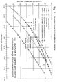
- FIG. 3 shows fiber loss curves for an NZDF fiber with varying degrees of water peak at 1385 nm, superimposing the location of Raman pumps for first-order pumping in the S-band, as well as second-order pumping in the extended L-band;
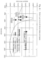
- FIG. 4 illustrates first- and second-order Raman pumping configurations in which a Raman pump must be placed in immediate proximity to the water peak;
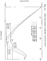
- FIG. 5 displays results of a calculation of the signal power in a Raman amplified, S-band single channel system, where the Raman pump is placed at 1395 nm to support operation in the vicinity of 1495 nm;
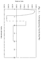
- FIG. 6 depicts the signal power evolution in the case of second-order Raman pumping for signal transmission in the L-band near 1580 nm;
- FIG. 7 illustrates the profile of a first optical fiber formed to exhibit the characteristics of the present invention, the dispersion curve for this fiber shown as curve C in FIG. 2;
- FIG. 8 illustrates the profile of a second optical fiber, also suitable to support Raman amplification in the S-band transmission region, the dispersion curve for this fiber shown as curve D in FIG. 2;
- FIG. 9 illustrates the profile of a third optical fiber according to the present invention, the third fiber having a dispersion curve essentially identical to that of the profile associated with FIG. 7, but with a larger effective area;
- FIG. 10 depicts the two separate preform sections that may be used to form the optical fiber of the present invention.
- transmission fiber 12 is formed as a distributed amplifier, dedicated to providing both transmission and amplification of an applied optical information signal I from a signal source, such as an optical transmitter 14.
- the length of transmission fiber 12 is typically at least 500 m, so as to allow for the optical interactions that produce Raman amplification to occur.
- the amplifier is counter-pumped, with a Raman source 16 coupled into the core of transmission fiber 12 through a coupler 18, as shown.
- a dispersion compensation module 20, as discussed below, is disposed in the signal path between the output of transmission fiber 12 and an optical receiver 22.
- the "water peak” comprises at least five sub-peaks, where the actual shape of the curve depends on the method of manufacture as well as how much hydroxyl is in the pure silica regions compared to the doped silica regions.
- the center of the water peak is cited in the fiber literature at various wavelengths ranging between 1380 and 1390 nm.
- a value of 1385 will be used as a definition of the "center" for the water peak in general. It is to be understood, however, that the teachings of the present invention are generally applicable to the above-mentioned complete range of 1380 - 1390 nm.
- FIG. 2 contains a graph of dispersion vs. wavelength for two different prior art fiber designs, as well as two fibers formed in accordance with the present invention.
- curves A and B illustrate the characteristics of two conventional prior art fibers, the TrueWave® REACH fiber (curve A) and the TrueWave® Reduced Sloped (RS) fiber (curve B). As shown, both of these fibers exhibit a negative dispersion value in the region required to generate a pump signal for S-band amplification.
- fiber A is impaired for Raman pumping for signal amplification near 1385 nm in the lower S-band by the presence of the ZDW near 1385 nm
- fiber B is impaired for both Raman pumping of C-band signals as well as signal propagation in the lower S-band by the presence of ZDW near 1460 nm. Therefore, neither fiber A nor fiber B fully qualifies as an SCL band fiber.
- the absolute value of dispersion should be approximately greater than 1 ps/nm-km; a similar condition is widely accepted as necessary to avoid signal-signal FWM in DWDM.
- the ZDW should not be located approximately equally spaced between the pumps and the signals. Together, these conditions imply that the ideal ZDW for an SCL band fiber will be located either shorter than the shortest pump wavelength or longer than the longest signal wavelength. Therefore, for an SCL fiber, the ZDW should be less than about 1360 nm or greater than 1620 nm. It is possible to design a Raman system around a poorly-placed ZDW, but at the cost of complexity or expense in the system design, or sub-optimal gain flattening.
- Fibers formed in accordance with the present invention exhibit both of these requirements: a dispersion of greater than +1 ps/nm-km at 1385 nm, and a ZDW of approximately 1350 nm. As shown, the dispersion value for fibers C and D is greater than 1 at 1375 nm, while less than 10 ps/nm-km for wavelengths greater than 1565 nm.
- Such a fiber formed in accordance with the present invention, in conjunction with appropriate dispersion compensation modules, will enable and support 40 Gb/s transmission and/or ultra-long haul transmission with Raman or hybrid Raman/EDFA amplification.
- a relevant and useful parameter is the ratio of the dispersion slope (measured in ps/nm 2 -km) to the dispersion at the central wavelength of the signal band (hereinafter referred to as the "relative dispersion slope" or RDS).
- RDS of the transmission fiber is equal to the RDS of a negative dispersion compensating fiber (as found in a compensation module), then precise cancellation of dispersion can be achieved over a wide range (e.g., ⁇ 15 to 20 nm). It has also been found that the match between a transmission fiber and dispersion compensating fiber with lower RDS will be generally superior to a combination of a transmission fiber and dispersion compensating fiber with higher RDS.
- a fiber formed in accordance with the present invention will have an RDS lower than 0.004/nm.
- FIG. 3 shows fiber loss curves for a non-zero dispersion fiber (NZDF) with varying degrees of water peak at 1385 nm, superimposing the location of the Raman pumps for first-order Raman pumping in the S-band and second-order Raman pumping in the extended L-band and upper C-band.
- NZDF non-zero dispersion fiber
- Non-zero dispersion fibers such as proposed here, have a higher GeO 2 content in the core than matched clad fibers, as well as a juxtaposition of multiple layers of doped material, thereby presenting more opportunities for stress and irregularities at the interfaces. These have the impact of raising the background loss (generally termed Rayleigh scattering), which varies as ⁇ -4 .
- NZDF fibers typically have higher background loss in the water peak region than matched clad fibers.
- An asymmetric Lorentzian curve is used to model in the water peak in FIG. 3, where the curve is actually a composite of multiple sub-peaks. Water peaks (at 1385 nm) of height 0.3, 0.35, 0.4, 0.35 and 0.5 dB/km are shown in FIG. 3. Associated losses at neighboring wavelengths relevant to the subsequent discussion are shown below in Table I. The lowest curve represents an OH loss approximately 10 mdB/km above the Rayleigh scattering baseline and can be considered as a nominal "zero water peak" NZDF silica fiber, whose core index is in the range of 0.4 to 0.5% ⁇ .
- Case (a) illustrates a first-order, single pump, narrow-band pump scheme
- case (b) illustrates a first-order, dual pump scheme for flat gain over a broader wavelength gain region.
- Raman pumps for broad, flat gain are typically spaced 15 to 20 nm apart, necessitating that full use of the lower S band requires two Raman pumps straddling the water peak.
- Case (c) is a second-order pumped Raman architecture for transmission in the L-band. It is to be understood that water peak loss and its variability impact the consistency of Raman gain, the average pump power required to achieve target Raman gain, and the OSNR of the amplifier.
- Raman gain variability due to simple variability in the pump region attenuation from fiber to fiber within a manufacturing distribution.
- a typical span for terrestrial transmission is approximately 100 km, built up from concatenated cable segments approximately 4 to 5 km in length.
- 20 to 25 fibers with 20-25 different loss values may be sampled in any given span.
- This averaging helps reduce the impact of variability in typical fiber transmission properties such as dispersion, mode field, or loss.
- the effective length varies between 15km and 9 km, respectively.
- the distributed Raman amplifier effectively comprises only four to six separate fibers, with the result that the effect of loss variation on Raman gain variation is a significant problem for the system design engineer.
- the values of Raman gain G at 1490 nm are 22.0, 17.4, and 14.5 dB, respectively. This is a range of 7.5 dB, which is over a factor of five times variation in Raman gain.
- a single pump, narrow band configuration may require up to (or greater than) 500mW pump power, which would most likely be supplied by a fiber laser source.
- Commercial low-noise laser diodes have output powers ranging from 200 to 350mW, and are available in gradations of 50 to 80mW of output power.
- a very broad band Raman system (e.g., converting the entire C and L bands) could require as many as five to six pumps, between 50 and 200mW each.
- a moderate band system might comprise two to three pumps of 100 to 300mW output power. In general, the shortest wavelength pump will require two to three times the power of the other system pumps.
- the smallest laser diode capable of handling the range of output powers required to compensate for fiber loss variability expected in the field would be used.
- the loss at 1395 nm varies by 25%, requiring pump power to be adjustable by 25% to achieve a targeted Raman gain.
- a margin of 50% pump power would be required at 1395 nm.
- FIG. 3 illustrates the spectral loss curve of an NZDF fiber and Raman pump placement relevant to S-band operation with first-order pumping and extended L-band operation with second-order pumping. These two schemes both require placing Raman pumps very close to the water peak.
- the impact of differing water peak loss on the evolution of signal power along a 100 km span is shown in FIG. 5 for the case of a single Raman pump at 1395 nm for signals in the S-band near 1490 nm (case (a) of FIG. 4).
- the signal power drops by the total span loss (22 dB for the exemplary case shown in FIG. 5, curve labeled 'No Raman gain') and then undergoes rapid amplification over a short section of high gain erbium-doped fiber.
- the gain per unit length is lower than for an EDFA but is distributed over a significant percentage of the transmission distance, so that the optical power in the fiber reaches a minimum mid-span and then begins to increase.
- L eff (1-exp( ⁇ pump *L span ))/ ⁇ pump .
- L eff (1-exp( ⁇ pump *L span ))/ ⁇ pump .
- a longer effective length means a greater degree of distributed amplification and results in a higher minimum signal power and a greater performance benefit through improved OSNR.
- a detailed understanding of the correlation between minimum signal power and improved OSNR requires the solution of differential equations describing the build-up of amplified spontaneous emission (ASE) in the amplifier. However, the physics can be summarized as follows: ASE refers to noise that is generated in the presence of gain, which is added to the signal being amplified.
- ASE power at the output of an ampli bomb comes from the ASE which is generated near the input of gain medium and then amplified exponentially along the remainder of the gain medium.
- a lumped amplifier such as an EDFA
- ASE is added to the signal over a very short distance (i.e., tens of meters) in a high gain per unit length amplifier fiber and the ASE itself experiences practically no fiber loss.
- ASE builds up more slowly in the presence of a lower gain per unit length so that it does experience the same attenuation as the signal itself. Therefore, ASE generated early in the span (in the range of 70 to 75 km for the cases of FIG. 5) will suffer fiber loss over 20 to 25 km in addition to being amplified by Raman gain. This reduces the exponential gain experienced by the ASE generated early in the amplifier, resulting in lower total ASE power and better OSNR.
- the minimum signal power in the span, the distance into the span at which the minimum occurs, the total ASE generated, and the resultant OSNR are all related.
- Optimum performance is obtained for the longest effective length, which requires minimum fiber loss at the Raman pump wavelengths. While the reduction in net Raman gain due to stronger pump attenuation can be countered by raising pump power, the deleterious impact of high attenuation near the water peak on OSNR cannot be mitigated.
- the second-order pumping paradigm uses an additional, lower wavelength Raman pump to amplify the Raman pump, extending the first-order scheme as diagrammed in FIG. 1.
- the basic advantage is that Raman gain penetrates farther into the span, leading to further benefit in OSNR.
- higher Raman pump powers are required.
- a second-order Raman pump is placed at 1375 nm, the first-order pump at 1475 nm, for amplifying signals in the range of 1580 nm.
- Such a single second-order pump, plus the single first-order pump configuration has been used in the literature to achieve the same gain flatness over a bandwidth of 30 nm as achieved by three first-order pumps.
- the total pump powers (first-order and second-order) required to achieve 15 dB of Raman gain are 703, 771, 841 and 973 mW for water peaks of, respectively, 0.3, 0.4, 0.5 and 0.7 dB/km.
- the power evolution curves are shown in FIG. 6.
- the minimum power in the span varies by over 1 dB, corresponding to approximately 1 dB deterioration of OSNR from the case of 0.3 dB/km to 0.7 dB/km water peak height. This degradation of Raman gain is less severe than the first-order case.
- the total power required to achieve the 15 dB of targeted gain becomes very significant for losses above the 0.30 dB/km lower limit on water peak. This is important since a high power damage phenomenon commonly known as the "fiber fuse" can occur in optical fibers that are handled or perturbed while carrying power levels of approximately one watt. It is therefore desirable to maintain Raman pumping levels as low as possible to enhance reliability.
- the fiber fuse occurs for a wide range of optical power levels, the value of constraining water peak to be less than 0.4 dB/km can readily be appreciated, since that limits the required total Raman pump power (in this exemplary case, to 75% of the approximately one watt value associated with initiation of the fiber fuse).
- the cost of the higher power Raman pump and the associated additional heat dissipation loads are, of course, undesirable in any case.
- an optical fiber for SCL band operation is defined in accordance with the present invention as a fiber which has both the appropriate dispersion curve to avoid FWM for signals and Raman pumps, and which has a water peak loss less then 0.4 dB/km (and preferably lower) to prevent OSNR degradation, high pump power costs and high power damage phenomena.
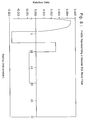
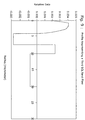
- FIGs. 7 - 9 illustrate the refractive index profiles of three exemplary fibers exhibiting the desired characteristics of the present invention.
- the y-axes show units of relative delta, which is defined as (n(r) - n clad )/n clad ).
- the standard radius of an optical fiber is 62.5 microns.
- fibers that exhibit an acceptable bending loss will have an effective area in the range of 50-65 ⁇ m 2 .
- the fiber shown in FIG. 7 has an effective area of 55 square microns, dispersion of 9 ps/nm/km, slope of 0.033 ps/nm 2 /km. and an RDS of 0.0037/nm, all at a wavelength of 1550 nm.
- FIG. 8 has an effective area of 55 square microns, dispersion of 8 ps/nm/km, a slope of 0.027 ps/nm 2 km, and an RDS of 0.0033/nm, again at a wavelength of 1550 nm.
- the fiber of FIG. 9 has an effective area of 60 square microns, dispersion of 9 ps/nm/km, a slope of 0.035 ps/nm 2 /km and an RDS of 0.0038/nm, all at 1550 nm.
- the fiber if FIG. 7 has a fiber cutoff less than 1275 nm, implying a cable cutoff that is 50 to 75 nm lower than still.
- the fiber of FIG. 9 has both fiber and cable cutoffs below 1200 nm. Thus, all are compatible with 1310 nm transmission, including cutoff and dispersion requirements. In all cases, the properties of the optical fibers produced using these preforms fall within the following prescription:
- the illustrated optical fiber profiles generally comprise five separate regions. Referring to FIG. 7, the regions are defined as central core region 30, trench region 32, ring region 34, depressed cladding region 36 and outer cladding region 38.
- the fiber of FIG. 8 illustrates a similar profile.
- the core region 30 and ring region 34 will typically comprise germanium-doped silica, while trench region 32 and depressed cladding region 36 will typically comprise fluorine-doped silica.
- Synthetic tubing used as substrates or overcladding tubes may be fluorine doped to contributed to forming depressed cladding region 36.
- Tubing may also contain Cl, consistent with processing methods used in production, where the Cl may induce small but incidental variations in index.
- Fabrication of regions 30, 32, 34 and 36 is generally completed as an intermediate step in perform manufacture; formation of region 38 is the actual overcladding step and may be accomplished by a rod-in-tube or soot deposition method.
- the desired attenuation at the water peak of 1385 nm is achieved by forming core region 30 and trench region 32 using a vapor-axial deposition (VAD) process.
- VAD vapor-axial deposition
- US Patent 6131,415 herein incorporated by reference
- VAD (or OVD) glass has the inherent advantage over MCVD glass of having an explicit dehydration step between soot deposition and sintering.
- the deposited soot is initially very "wet" due to the oxy-hydrogen flame in VAD or OVD, subsequent dehydration in Cl 2 renders the core material dry enough to exhibit a water peak consistently only 0.005 to 0.010 dB/km above the Rayleigh scattering background, corresponding to OH concentration of a fraction of a ppb.
- No hydrogen source is purposely present during the deposition of MCVD soot.
- trace hydrogen impurities that are present are immediately sintered into the glass structure with no additional dehydration step.
- the MCVD substrate tube - if less dry than the deposited material - may also contribute OH concentration which significantly overlaps the optical power distribution.
- VAD or OVD glass As a result, there is a net advantage in using VAD or OVD glass to form regions 30 and 34, where approximately 98 - 99% of the optical power resides.
- the VAD/OVD process is not adept at forming an additional layer of up-doped (e.g., germanium-doped) material (such as ring region 34) outside the trench region 32 without resorting to schemes that compromise the advantage of ultra-dryness as described above.
- FIG. 10 illustrates the two separate preform sections, a first preform section 40 comprising core region 30 and trench region 32, and a second preform section 42 comprising ring region 34, depressed cladding region 36, and outer cladding 38.
- the interface between the two separate performs sections 40 and 42 is formed in a chlorine (or fluorine) atmosphere (or a mixture of chlorine and fluorine, or some other appropriate atmosphere), resulting in the formation of an ultra-dry interface to avoid adding OH attenuation at 1383 nm from the step of mating the VAD inner core to the MCVD outer core.
- a desirable variation on this method is to use high purity, doped, synthetic silica tubes to form regions 34 and 36, and form interfaces between regions 34 and 36 in a chlorine (or other ultra-dry) atmosphere.
- a chlorine or fluorine atmosphere is supplied at high temperature by thermal breakdown of various chemicals containing Cl or F atoms, including Cl 2 , CF 4 , C 2 F 6 , CCl 4 , SiF 4 or SF 6 , which may be used alone or in concert.
- the present invention provides a non-zero dispersion shifted fiber that combines a low water peak attenuation value with a properly located zero dispersion wavelength to provide for S-band amplification without adversely affecting the transmission or amplification of signals operating in either the C-band or L-band regions.
- the very low water peak attenuation is considered necessary as an adjunct to having the zero dispersion wavelength in the proper location since Raman pumps useful for S-band signals will have a pump source "sitting on" the water peak wavelength of 1385 nm.
- Raman amplification for S-band signals will be both inefficient and variable, and therefore suffer degradation in system performance..
Landscapes
- Physics & Mathematics (AREA)
- Chemical & Material Sciences (AREA)
- Engineering & Computer Science (AREA)
- Dispersion Chemistry (AREA)
- Optics & Photonics (AREA)
- Signal Processing (AREA)
- Computer Networks & Wireless Communication (AREA)
- Electromagnetism (AREA)
- General Physics & Mathematics (AREA)
- Manufacturing & Machinery (AREA)
- Organic Chemistry (AREA)
- Materials Engineering (AREA)
- Life Sciences & Earth Sciences (AREA)
- Geochemistry & Mineralogy (AREA)
- General Life Sciences & Earth Sciences (AREA)
- Nonlinear Science (AREA)
- Optical Modulation, Optical Deflection, Nonlinear Optics, Optical Demodulation, Optical Logic Elements (AREA)
- Optical Communication System (AREA)
- Optical Fibers, Optical Fiber Cores, And Optical Fiber Bundles (AREA)
Applications Claiming Priority (2)
| Application Number | Priority Date | Filing Date | Title |
|---|---|---|---|
| US670013 | 1996-06-25 | ||
| US10/670,013 US7164833B2 (en) | 2003-09-24 | 2003-09-24 | Optical fiber for improved performance in S-, C- and L-bands |
Publications (3)
| Publication Number | Publication Date |
|---|---|
| EP1519501A2 true EP1519501A2 (fr) | 2005-03-30 |
| EP1519501A3 EP1519501A3 (fr) | 2008-01-23 |
| EP1519501B1 EP1519501B1 (fr) | 2015-11-11 |
Family
ID=34194815
Family Applications (1)
| Application Number | Title | Priority Date | Filing Date |
|---|---|---|---|
| EP04022110.3A Expired - Lifetime EP1519501B1 (fr) | 2003-09-24 | 2004-09-16 | Fibre optique pour des performances améliorées dans les bandes S, C et L |
Country Status (4)
| Country | Link |
|---|---|
| US (1) | US7164833B2 (fr) |
| EP (1) | EP1519501B1 (fr) |
| JP (1) | JP2005099801A (fr) |
| CN (2) | CN101776781A (fr) |
Cited By (1)
| Publication number | Priority date | Publication date | Assignee | Title |
|---|---|---|---|---|
| WO2007125540A1 (fr) * | 2006-05-02 | 2007-11-08 | Sterlite Optical Technologies Ltd. | Fibre optique a dispersion optimisee pour transmision optique a large bande |
Families Citing this family (8)
| Publication number | Priority date | Publication date | Assignee | Title |
|---|---|---|---|---|
| KR100668284B1 (ko) * | 2004-12-14 | 2007-01-16 | 한국전자통신연구원 | S밴드 분리형 라만 증폭기를 위한 분산보상광섬유 |
| US20070003198A1 (en) * | 2005-06-29 | 2007-01-04 | Lance Gibson | Low loss optical fiber designs and methods for their manufacture |
| US7502539B2 (en) * | 2006-09-29 | 2009-03-10 | Corning Incorporated | Rare earth doped optical fiber |
| WO2009093304A1 (fr) * | 2008-01-22 | 2009-07-30 | Mitsubishi Electric Corporation | Système de transmission optique et répéteur |
| US8687932B2 (en) * | 2011-09-21 | 2014-04-01 | Ofs Fitel, Llc | Optimized ultra large area optical fibers |
| CN103928839A (zh) * | 2014-04-23 | 2014-07-16 | 湖南大学 | 一种u波段高功率皮秒脉冲激光产生方法 |
| CN115411596A (zh) * | 2021-05-28 | 2022-11-29 | 华为技术有限公司 | 掺铒光纤和掺铒光纤的制备方法 |
| CN114578473B (zh) * | 2022-02-24 | 2024-12-27 | 高卫卫 | 一种宽频带低色散的光导纤维及其制备方法 |
Citations (1)
| Publication number | Priority date | Publication date | Assignee | Title |
|---|---|---|---|---|
| WO2003071325A1 (fr) | 2002-02-15 | 2003-08-28 | Corning Incorporated | Fibre optique decalee a dispersion de pente faible |
Family Cites Families (3)
| Publication number | Priority date | Publication date | Assignee | Title |
|---|---|---|---|---|
| US6131415A (en) | 1997-06-20 | 2000-10-17 | Lucent Technologies Inc. | Method of making a fiber having low loss at 1385 nm by cladding a VAD preform with a D/d<7.5 |
| US5905838A (en) * | 1998-02-18 | 1999-05-18 | Lucent Technologies Inc. | Dual window WDM optical fiber communication |
| JP2001255563A (ja) * | 2000-03-08 | 2001-09-21 | Sumitomo Electric Ind Ltd | 光伝送システム |
-
2003
- 2003-09-24 US US10/670,013 patent/US7164833B2/en not_active Expired - Lifetime
-
2004
- 2004-09-16 EP EP04022110.3A patent/EP1519501B1/fr not_active Expired - Lifetime
- 2004-09-20 CN CN201010104362A patent/CN101776781A/zh active Pending
- 2004-09-20 CN CN200410078088.5A patent/CN1601365A/zh active Pending
- 2004-09-24 JP JP2004276813A patent/JP2005099801A/ja active Pending
Patent Citations (1)
| Publication number | Priority date | Publication date | Assignee | Title |
|---|---|---|---|---|
| WO2003071325A1 (fr) | 2002-02-15 | 2003-08-28 | Corning Incorporated | Fibre optique decalee a dispersion de pente faible |
Cited By (1)
| Publication number | Priority date | Publication date | Assignee | Title |
|---|---|---|---|---|
| WO2007125540A1 (fr) * | 2006-05-02 | 2007-11-08 | Sterlite Optical Technologies Ltd. | Fibre optique a dispersion optimisee pour transmision optique a large bande |
Also Published As
| Publication number | Publication date |
|---|---|
| JP2005099801A (ja) | 2005-04-14 |
| EP1519501A3 (fr) | 2008-01-23 |
| EP1519501B1 (fr) | 2015-11-11 |
| CN101776781A (zh) | 2010-07-14 |
| CN1601365A (zh) | 2005-03-30 |
| US20050063656A1 (en) | 2005-03-24 |
| US7164833B2 (en) | 2007-01-16 |
Similar Documents
| Publication | Publication Date | Title |
|---|---|---|
| Fukuchi et al. | 10.92-Tb/s (273× 40-Gb/s) triple-band/ultra-dense WDM optical-repeatered transmission experiment | |
| US6903865B2 (en) | Communication system using S-band Er-doped fiber amplifiers with depressed cladding | |
| EP2131455B1 (fr) | Amplificateur Raman avec pompage bidirectionnel | |
| US7123803B2 (en) | Optical fiber and optical transmission line and optical communication system including such optical fiber | |
| US6943935B2 (en) | Dispersion-managed cable for raman-assisted transmission | |
| US9164230B2 (en) | High-power double-cladding-pumped (DC) erbium-doped fiber amplifier (EDFA) | |
| Ono et al. | S-band Erbium-doped fiber amplifiers with a multistage configuration-design, characterization, and gain tilt compensation | |
| JP2002514017A (ja) | 分布増幅をもつ分散制御光導波路及びシステム | |
| US6941054B2 (en) | Optical transmission link with low slope, raman amplified fiber | |
| JP2002207136A (ja) | 光ファイバ、非線型性光ファイバ、それを用いた光増幅器、波長変換器、及び光ファイバの製造方法 | |
| EP1519501B1 (fr) | Fibre optique pour des performances améliorées dans les bandes S, C et L | |
| US9231365B1 (en) | Discrete raman amplifier | |
| AU6473100A (en) | Optical transmission line, method for manufacturing optical transmission line, and optical transmission system | |
| US7154663B2 (en) | Dispersion compensating fiber for S-band discrete Raman amplifier | |
| JP4532079B2 (ja) | 光ファイバ | |
| US20250105578A1 (en) | Optical fiber for amplification, optical amplifier, and method for controlling optical amplifier | |
| CN100582825C (zh) | 具有光放大功能的传输光纤及其制造方法 | |
| JP7513122B2 (ja) | 光ファイバ増幅器 | |
| CN100406933C (zh) | 光纤、使用该光纤的光模块和拉曼放大器 | |
| JP2000047048A (ja) | 分散スロープ補償光ファイバ | |
| US6865303B2 (en) | Method and apparatus for reducing multi-path interference in dispersion compensation systems | |
| Amin et al. | Design of Clad-pumped 3M-EDFA for MDM-WDM system with 3× 16 channels | |
| US7046433B2 (en) | Optical fiber, and optical module and Raman amplifier using the optical fiber | |
| Bayart | Optical fiber amplification technology | |
| Masuda et al. | TDFA and ultra-wide band amplifiers |
Legal Events
| Date | Code | Title | Description |
|---|---|---|---|
| PUAI | Public reference made under article 153(3) epc to a published international application that has entered the european phase |
Free format text: ORIGINAL CODE: 0009012 |
|
| AK | Designated contracting states |
Kind code of ref document: A2 Designated state(s): AT BE BG CH CY CZ DE DK EE ES FI FR GB GR HU IE IT LI LU MC NL PL PT RO SE SI SK TR |
|
| AX | Request for extension of the european patent |
Extension state: AL HR LT LV MK |
|
| PUAL | Search report despatched |
Free format text: ORIGINAL CODE: 0009013 |
|
| RIC1 | Information provided on ipc code assigned before grant |
Ipc: G02B 6/02 20060101ALI20071207BHEP Ipc: H04B 10/17 20060101AFI20041124BHEP Ipc: H04B 10/18 20060101ALI20071207BHEP |
|
| AK | Designated contracting states |
Kind code of ref document: A3 Designated state(s): AT BE BG CH CY CZ DE DK EE ES FI FR GB GR HU IE IT LI LU MC NL PL PT RO SE SI SK TR |
|
| AX | Request for extension of the european patent |
Extension state: AL HR LT LV MK |
|
| 17P | Request for examination filed |
Effective date: 20080617 |
|
| AKX | Designation fees paid |
Designated state(s): DE FR GB |
|
| 17Q | First examination report despatched |
Effective date: 20100330 |
|
| RAP1 | Party data changed (applicant data changed or rights of an application transferred) |
Owner name: OFS FITEL, LLC |
|
| REG | Reference to a national code |
Ref country code: DE Ref legal event code: R079 Ref document number: 602004048199 Country of ref document: DE Free format text: PREVIOUS MAIN CLASS: H04B0010170000 Ipc: H04B0010250700 |
|
| RIC1 | Information provided on ipc code assigned before grant |
Ipc: H04B 10/291 20130101ALI20150416BHEP Ipc: C03B 37/012 20060101ALI20150416BHEP Ipc: H04B 10/2507 20130101AFI20150416BHEP Ipc: G02B 6/036 20060101ALI20150416BHEP Ipc: G02B 6/02 20060101ALI20150416BHEP Ipc: H04B 10/2563 20130101ALI20150416BHEP |
|
| GRAP | Despatch of communication of intention to grant a patent |
Free format text: ORIGINAL CODE: EPIDOSNIGR1 |
|
| INTG | Intention to grant announced |
Effective date: 20150527 |
|
| GRAS | Grant fee paid |
Free format text: ORIGINAL CODE: EPIDOSNIGR3 |
|
| GRAA | (expected) grant |
Free format text: ORIGINAL CODE: 0009210 |
|
| AK | Designated contracting states |
Kind code of ref document: B1 Designated state(s): DE FR GB |
|
| REG | Reference to a national code |
Ref country code: GB Ref legal event code: FG4D |
|
| REG | Reference to a national code |
Ref country code: DE Ref legal event code: R096 Ref document number: 602004048199 Country of ref document: DE |
|
| REG | Reference to a national code |
Ref country code: DE Ref legal event code: R097 Ref document number: 602004048199 Country of ref document: DE |
|
| PLBE | No opposition filed within time limit |
Free format text: ORIGINAL CODE: 0009261 |
|
| STAA | Information on the status of an ep patent application or granted ep patent |
Free format text: STATUS: NO OPPOSITION FILED WITHIN TIME LIMIT |
|
| 26N | No opposition filed |
Effective date: 20160812 |
|
| REG | Reference to a national code |
Ref country code: FR Ref legal event code: PLFP Year of fee payment: 13 |
|
| REG | Reference to a national code |
Ref country code: FR Ref legal event code: PLFP Year of fee payment: 14 |
|
| REG | Reference to a national code |
Ref country code: FR Ref legal event code: PLFP Year of fee payment: 15 |
|
| PGFP | Annual fee paid to national office [announced via postgrant information from national office to epo] |
Ref country code: GB Payment date: 20180927 Year of fee payment: 15 |
|
| PGFP | Annual fee paid to national office [announced via postgrant information from national office to epo] |
Ref country code: DE Payment date: 20181029 Year of fee payment: 15 |
|
| PGFP | Annual fee paid to national office [announced via postgrant information from national office to epo] |
Ref country code: FR Payment date: 20181025 Year of fee payment: 15 |
|
| REG | Reference to a national code |
Ref country code: DE Ref legal event code: R119 Ref document number: 602004048199 Country of ref document: DE |
|
| PG25 | Lapsed in a contracting state [announced via postgrant information from national office to epo] |
Ref country code: DE Free format text: LAPSE BECAUSE OF NON-PAYMENT OF DUE FEES Effective date: 20200401 |
|
| GBPC | Gb: european patent ceased through non-payment of renewal fee |
Effective date: 20190916 |
|
| PG25 | Lapsed in a contracting state [announced via postgrant information from national office to epo] |
Ref country code: FR Free format text: LAPSE BECAUSE OF NON-PAYMENT OF DUE FEES Effective date: 20190930 Ref country code: GB Free format text: LAPSE BECAUSE OF NON-PAYMENT OF DUE FEES Effective date: 20190916 |