EP1519336B1 - Device for communicating with an equipment - Google Patents
Device for communicating with an equipment Download PDFInfo
- Publication number
- EP1519336B1 EP1519336B1 EP04022550A EP04022550A EP1519336B1 EP 1519336 B1 EP1519336 B1 EP 1519336B1 EP 04022550 A EP04022550 A EP 04022550A EP 04022550 A EP04022550 A EP 04022550A EP 1519336 B1 EP1519336 B1 EP 1519336B1
- Authority
- EP
- European Patent Office
- Prior art keywords
- communication device
- emergency stop
- stop button
- equipment
- tray
- Prior art date
- Legal status (The legal status is an assumption and is not a legal conclusion. Google has not performed a legal analysis and makes no representation as to the accuracy of the status listed.)
- Not-in-force
Links
Images

Classifications
-
- G—PHYSICS
- G08—SIGNALLING
- G08C—TRANSMISSION SYSTEMS FOR MEASURED VALUES, CONTROL OR SIMILAR SIGNALS
- G08C17/00—Arrangements for transmitting signals characterised by the use of a wireless electrical link
- G08C17/02—Arrangements for transmitting signals characterised by the use of a wireless electrical link using a radio link
-
- H—ELECTRICITY
- H01—ELECTRIC ELEMENTS
- H01H—ELECTRIC SWITCHES; RELAYS; SELECTORS; EMERGENCY PROTECTIVE DEVICES
- H01H3/00—Mechanisms for operating contacts
- H01H3/02—Operating parts, i.e. for operating driving mechanism by a mechanical force external to the switch
- H01H3/022—Emergency operating parts, e.g. for stop-switch in dangerous conditions
Definitions
- the invention relates to a device for communication with a system, in particular for operating and monitoring an automation system in industrial production.
- Output devices or in other words observation devices, are, for example, warning lights, alphanumeric or graphic displays which inform the plant operator about the current state of the plant.
- Input devices or in other words HMI devices, are e.g. Switches, knobs or keyboards for alphanumeric input that allow the operator to interact with the system.
- HMI devices for the purpose of communication between user and equipment, so-called HMI devices, hereinafter referred to as communication equipment, are fixed to the equipment itself or e.g. installed in the production hall where the system is located.
- a typical communication device has a handy housing on which input and output devices are arranged. The data exchange with the system or with its control takes place via a permanently installed connection cable.
- wired communication devices For very large or difficult to access systems wired communication devices are no longer manageable. For this purpose, there are mobile, ie freely movable, wirelessly communicating with the system and battery-powered communication devices, which handle the data exchange with the system via wireless connection.
- emergency stop buttons are marked red-yellow and must always be ready for use. Pressing the emergency stop button causes the power to be switched off immediately on the entire system.
- the emergency stop buttons are routed in a conventional manner via a separate emergency stop circuit next to the fieldbus on the system or connected to this.
- a so-called safety-oriented field bus can be used recently for connecting the emergency stop button, which provides the same safety reserves for emergency stop of the corresponding system as a separate emergency stop circuit.
- the mobile, wireless communication devices are also equipped in many cases with security functions, with the help of which the safe state of the system can be achieved in case of danger. Since such devices are necessarily battery operated and the information is transmitted over a radio link, the availability of the emergency stop function is not available. A termination of the radio link or a complete emptying of the battery located in the mobile communication device would lead namely to tearing off the communication between the communication device and system, so the emergency stop button would be ineffective in this case.
- stop function is realized.
- the stop function is usually implemented by a stop button on the communication device, which may not be red-yellow due to its limited availability. If the communication device is functioning properly, pressing this button will also cause the system to shut down immediately or to immediately switch off the power to the entire system, ie it will have the same functionality as the emergency stop button.
- stop button located on the mobile communication device is not necessarily assigned to a specific machine if the mobile communication device is stored anywhere in a production hall. Therefore, even with a functioning communication device, pressing the stop button does not necessarily cause the machine in the vicinity to come to a standstill.
- Object of the present invention is to provide a device in which the security-relevant handling of a mobile communication device is simplified.
- the object is achieved by a device for communication with a system, in particular for operating and monitoring an automation system in industrial production, with a mobile communication device for wireless data exchange with the system.
- Firmly connected to the system is a shelf in which the communication device can be stored.
- the shelf has an emergency stop button for switching off the system.
- a similar system will be in DE 19 946 441 disclosed.
- Trays for mobile communication devices are typically, e.g. in the form of a so-called docking station, equipped with a power supply via which the battery located in the communication device accumulator is charged.
- the docking station forms a defined storage for the operating device, i. after completion of the use of the same should always be stored in the filing.
- this may be done by appropriate monitoring, e.g. be ensured by the workshop master.
- An assignment of a mobile operating device to a specific system or machine is improved in that the filing is firmly connected to the system.
- the communication device is not stored elsewhere, e.g. in the master cabin and thus the plant is assigned more clearly.
- the emergency stop button on the fixed shelf is hard-wired and thus functional at all times. If the radio connection is interrupted with the communication device connected, and thus the stop button is inoperative, there is an emergency stop button in the immediate range, namely directly next to the communication device. Also, the operator knows so in the case of removed from the tray communication device and tearing off the radio contact that at least at the storage location of the communication device, an emergency stop button is available, to which he can hurry in case of danger.
- the administrative effort for the path closing the communication device is eliminated because it is permissible because of the availability of a permanently functioning emergency stop button to permanently store the communication device in the tray.
- Fig. 1 shows an automation system 2 with a mobile communication device 4, which is process-coupled with the automation system 2, ie wirelessly exchanges for operating and monitoring the system 2 with this data.
- the automation system 2 comprises a machine 6 and a controller 6 controlling the machine 8, and a tray 10 for the communication device 4 and a radio base station 12.
- a first emergency stop button 14 is also included, in addition to the controller. 8 on a wall of the machine, not shown, the machine 6 containing fixedly mounted.
- a second emergency stop button 16 is attached to the housing 18 of the tray 10. The tray 10 in turn is firmly installed on the machine 6.
- All components of the automation system 2 are interconnected via a safety-related fieldbus 20.
- Security-oriented in this context means that in such a fieldbus 20, the functionality of Emergency stop button 14,16 is ensured at all times.
- the emergency stop buttons 14,16 may therefore be made in red-yellow color.
- a pressure on an emergency stop button 14, 16 leads to immediate voltage disconnection on all components of the automation system. 2
- the communication device 4 has input and output devices 22 (not shown), e.g. in the form of a surrounding of control buttons display, with which a communication device 4 serving, not shown operator the automation system 2 can operate and monitor.
- the communication between communication device 4 and system 2 takes place between the antennas 24, 26 attached to the radio base station 12 and the communication device 4 along a radio path 28 indicated by a double arrow.
- a stop button 30 is attached.
- the stop button 30 has the same functionality as the emergency stop button 14, 16. When the stop button 30 is pressed, the voltage is switched off in the entire automation system 2. However, since the stop button 30 is located on the battery-powered communication device 4, which is also freely movable, it must not be red-yellow according to the above-mentioned industry standards Emergency stop button must be marked. The functioning of the stop button 30 presupposes namely that the communication device 4 is powered from the battery contained therein, not shown, so this battery is not completely emptied and that the radio link 28 is working properly. In addition, the communication device 4 may be e.g. not located outside the range of the radio link 28 remote from the radio base station 12.
- the operator removes the communication device 4 from the tray 10 at the beginning of use. Therefore, in this case, he knows that in the event of a malfunction in the communication device 4, at least on the tray 10 a permanently functioning Emergency stop button 16 is available to which he can hurry in case of danger.
- the communication device 4 since the communication device 4 is dedicated to the tray 10, it is not caused to drop the communication device 4 at any other location because it is also recharged only in the tray 10 in which a power supply not shown.
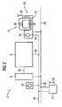
- Fig. 2 The situation of an inserted in the tray 10 communication device 4 is in Fig. 2 shown.
- Fig. 2 shows the same automation system as Fig. 1
- the safety-related fieldbus 20 is replaced by a standard fieldbus 32 without special security features.
- the emergency stop buttons 14, 16 are not connected to each other via the field bus 32, but via a separately installed emergency stop circuit 34.
- the emergency stop circuit 34 acts on the machine 6 and can also, as related to Fig. 1 described via the stop button 30 are triggered. Therefore, the radio base station 12 receiving the corresponding radio signal is also connected to the emergency stop circuit 34 to generate the emergency stop signal.
- Fig. 2 is the communication device 4 in its associated tray 10 and is disabled. There is no radio connection between the antennas 24 and 26, which is why a pressure on the stop button 30 is ineffective. Nevertheless, the in Fig. 2 illustrated situation a permissible according to industry standard arrangement, since in the immediate vicinity of the stop button 30, namely the housing 18 of the tray 10 of the emergency stop button 16 is located, which is ready for use at any time. Since the emergency stop button 16 is executed red-yellow, an operator of the system is not tempted to press in case of danger first on the example gray running stop button 30, but is immediately the familiar and memorable red-yellow emergency stop Press button 16.
- FIG. 2 Another security aspect in Fig. 2 is that, for example, at shift change is easily controlled whether the communication device 4 is also inserted in its tray 10. This is particularly useful because on the shelf 10 usually also a charge of the communication device 4 located in the accumulator, not shown, takes place and so at the beginning of the shift layer, the communication device 4 is recharged and thus ready for operation.
Abstract
Description
Die Erfindung betrifft eine Einrichtung zur Kommunikation mit einer Anlage insbesondere zum Bedienen und Beobachten einer Automatisierungsanlage in der industriellen Fertigung.The invention relates to a device for communication with a system, in particular for operating and monitoring an automation system in industrial production.
Industrielle Automatisierungsanlagen benötigen mit ihnen in Verbindung stehende Ein- oder Ausgabegeräte, um betrieben werden zu können; hierbei handelt es sich um die sogenannte Prozesskopplung. Ausgabegeräte, oder mit anderen Worten Beobachtungsgeräte, sind zum Beispiel Kontrollleuchten, alphanumerische oder graphische Displays, die den Anlagenbediener über den aktuellen Anlagenzustand informieren. Eingabegeräte, oder mit anderen Worten Bediengeräte, sind z.B. Schalter, Drehknöpfe oder Tastaturen zur alphanumerischen Eingabe, die es dem Bediener ermöglichen, auf die Anlage einzuwirken.Industrial automation equipment requires associated input or output devices to operate; this is the so-called process coupling. Output devices, or in other words observation devices, are, for example, warning lights, alphanumeric or graphic displays which inform the plant operator about the current state of the plant. Input devices, or in other words HMI devices, are e.g. Switches, knobs or keyboards for alphanumeric input that allow the operator to interact with the system.
In herkömmlicher Weise sind zum Zweck der Kommunikation zwischen Benutzer und Anlage sogenannte Bedien- und Beobachtungsgeräte, im folgenden kurz Kommunikationsgerät genannt, fest an der Anlage selbst oder z.B. in der Fertigungshalle, in der sich die Anlage befindet, installiert. Ein typisches Kommunikationsgerät weist ein handliches Gehäuse auf, an dem Ein- und Ausgabegeräte angeordnet sind. Der Datenaustausch mit der Anlage bzw. mit deren Steuerung erfolgt über eine fest installierte Anschlussleitung.Conventionally, for the purpose of communication between user and equipment, so-called HMI devices, hereinafter referred to as communication equipment, are fixed to the equipment itself or e.g. installed in the production hall where the system is located. A typical communication device has a handy housing on which input and output devices are arranged. The data exchange with the system or with its control takes place via a permanently installed connection cable.
Bei sehr großen oder schwer zugänglichen Anlagen sind kabelgebundene Kommunikationsgeräte nicht mehr handhabbar. Hierzu existieren mobile, also frei bewegliche, drahtlos mit der Anlage kommunizierende und batteriebetriebene Kommunikationsgeräte, welche den Datenaustausch mit der Anlage per Funkverbindung abwickeln.For very large or difficult to access systems wired communication devices are no longer manageable. For this purpose, there are mobile, ie freely movable, wirelessly communicating with the system and battery-powered communication devices, which handle the data exchange with the system via wireless connection.
Gemäß verschiedener Industrienormen müssen Anlagen mit sogenannten Not-Aus-Tastern ausgerüstet sein. Diese sind rot-gelb gekennzeichnet und müssen stets einsatzbereit sein. Ein Druck auf den Not-Aus-Taster bewirkt die sofortige Spannungsabschaltung an der gesamten Anlage. Die Not-Aus-Taster sind in herkömmlicher Weise über einen separaten Not-Aus-Kreis neben dem Feldbus an der Anlage verlegt bzw. mit dieser verbunden. Alternativ zum Not-Aus-Kreis kann in jüngerer Zeit zum Anschluss der Not-Aus-Taster ein sogenannter sicherheitsgerichteter Feldbus verwendet werden, der zur Not-Aus-Abschaltung der entsprechenden Anlage die gleichen Sicherheitsreserven bietet wie ein separater Not-Aus-Kreis.According to various industrial standards, systems must be equipped with so-called emergency stop buttons. These are marked red-yellow and must always be ready for use. Pressing the emergency stop button causes the power to be switched off immediately on the entire system. The emergency stop buttons are routed in a conventional manner via a separate emergency stop circuit next to the fieldbus on the system or connected to this. As an alternative to the emergency stop circuit, a so-called safety-oriented field bus can be used recently for connecting the emergency stop button, which provides the same safety reserves for emergency stop of the corresponding system as a separate emergency stop circuit.
Auch die mobilen, drahtlos arbeitenden Kommunikationsgeräte sind in vielen Fällen mit Sicherheitsfunktionen ausgestattet, mit Hilfe derer im Gefahrenfalle der sichere Anlagenzustand erreicht werden kann. Da derartige Geräte zwangsläufig batteriebetrieben sind und die Informationsübertragung über eine Funkstrecke erfolgt, ist die Dauerverfügbarkeit der Not-Aus-Funktion nicht gegeben. Ein Abbruch der Funkverbindung oder eine vollständige Entleerung des im mobilen Kommunikationsgerätes befindlichen Akkus würde nämlich zum Abreißen der Kommunikation zwischen Kommunikationsgerät und Anlage führen, weshalb der Not-Aus-Taster in diesem Fall wirkungslos wäre.The mobile, wireless communication devices are also equipped in many cases with security functions, with the help of which the safe state of the system can be achieved in case of danger. Since such devices are necessarily battery operated and the information is transmitted over a radio link, the availability of the emergency stop function is not available. A termination of the radio link or a complete emptying of the battery located in the mobile communication device would lead namely to tearing off the communication between the communication device and system, so the emergency stop button would be ineffective in this case.
Für funkbasierte Kommunikationsgeräte ist deshalb die sogenannte Stop-Funktion realisiert. Die Stop-Funktion wird in der Regel durch einen Stop-Taster am Kommunikationsgerät realisiert, der wegen seiner eingeschränkten Verfügbarkeit aber nicht rot-gelb ausgeführt sein darf. Bei ordnungsgemäß funktionierendem Kommunikationsgerät bewirkt ein Druck auf diesen Taster ebenfalls den sofortigen Stillstand der Anlage bzw. die sofortige Spannungsabschaltung an der gesamten Anlage, besitzt also die gleiche Funktionalität wie der Not-Aus-Taster.For radio-based communication devices, therefore, the so-called stop function is realized. The stop function is usually implemented by a stop button on the communication device, which may not be red-yellow due to its limited availability. If the communication device is functioning properly, pressing this button will also cause the system to shut down immediately or to immediately switch off the power to the entire system, ie it will have the same functionality as the emergency stop button.
Ein weiteres Sicherheitsrisiko ist, dass der am mobilen Kommunikationsgerät befindliche Stop-Taster nicht zwangsläufig einer bestimmten Maschine zuzuordnen ist, wenn das mobile Kommunikationsgerät an beliebiger Stelle in einer Fertigungshalle abgelegt ist. Selbst bei funktionierendem Kommunikationsgerät bewirkt ein Druck auf den Stop-Taster deshalb nicht zwangsläufig den Stillstand der sich in der Nähe befindenden Maschine.Another security risk is that the stop button located on the mobile communication device is not necessarily assigned to a specific machine if the mobile communication device is stored anywhere in a production hall. Therefore, even with a functioning communication device, pressing the stop button does not necessarily cause the machine in the vicinity to come to a standstill.
Gemäß verschiedener Sicherheitsvorschriften müssen deshalb mobile Bediengeräte, die nicht in Betrieb sind, z.B. weggeschlossen werden. Das Wegschließen des Gerätes ist zum einen organisatorisch aufwendig, zum anderen sind derartige administrative Vorschriften sehr fehleranfällig, z.B. wenn das Wegschließen des Gerätes vergessen wird.Therefore, according to various safety regulations, mobile operating devices that are not in operation, e.g. be locked away. The path closure of the device is on the one hand organisationally complex, on the other hand such administrative regulations are very error-prone, e.g. if the path closing of the device is forgotten.
Aufgabe der vorliegenden Erfindung ist es, eine Einrichtung anzugeben, bei der die sicherheitsrelevante Handhabung eines mobilen Kommunikationsgerätes vereinfacht ist.Object of the present invention is to provide a device in which the security-relevant handling of a mobile communication device is simplified.
Die Aufgabe wird gelöst durch eine Einrichtung zur Kommunikation mit einer Anlage, insbesondere zum Bedienen und Beobachten einer Automatisierungsanlage in der industriellen Fertigung, mit einem mobilen Kommunikationsgerät zum drahtlosen Datenaustausch mit der Anlage. Mit der Anlage fest verbunden ist eine Ablage, in der das Kommunikationsgerät ablegbar ist. An der Ablage ist ein Not-Aus-Taster zur Abschaltung der Anlage angebracht. Ein ähnliches System wird in
Ablagen für mobile Kommunikationsgeräte sind in der Regel, z.B. in Form einer sogenannten Docking-Station, mit einer Stromversorgung ausgerüstet, über welche der sich als Batterie im Kommunikationsgerät befindliche Akkumulator aufgeladen wird.Trays for mobile communication devices are typically, e.g. in the form of a so-called docking station, equipped with a power supply via which the battery located in the communication device accumulator is charged.
Solange das Kommunikationsgerät in der Ablage liegt, ist es also jederzeit mit ausreichend Energie versorgt und betriebsbereit, solange die Funkverbindung funktioniert. Dies erhöht die Verfügbarkeit des am Kommunikationsgerät angebrachten Stop-Tasters, so lange sich das Kommunikationsgerät in der Ablage befindet.As long as the communication device is in the storage, it is therefore always supplied with sufficient energy and ready for use, as long as the radio connection works. This increases the availability of the stop button attached to the communication device as long as the communication device is in the storage.
Die Docking Station bildet eine definierte Ablage für das Bediengerät, d.h. nach Beendigung der Benutzung desselben sollte dieses stets in der Ablage abgelegt werden. Dies kann gegebenenfalls durch eine entsprechende Überwachung, z.B. durch den Werkstattmeister sichergestellt werden. Eine Zuordnung eines mobilen Bediengerätes zu einer bestimmten Anlage bzw. Maschine ist dadurch verbessert, dass die Ablage an der Anlage fest verbunden ist. Das Kommunikationsgerät wird nicht an anderer Stelle abgelegt, z.B. in der Meisterkabine und ist somit der Anlage deutlicher zugeordnet.The docking station forms a defined storage for the operating device, i. after completion of the use of the same should always be stored in the filing. Optionally, this may be done by appropriate monitoring, e.g. be ensured by the workshop master. An assignment of a mobile operating device to a specific system or machine is improved in that the filing is firmly connected to the system. The communication device is not stored elsewhere, e.g. in the master cabin and thus the plant is assigned more clearly.
Der Not-Aus-Taster an der fest installierten Ablage ist fest verdrahtet und somit jederzeit funktionsfähig. Sollte bei einliegendem Kommunikationsgerät die Funkverbindung unterbrochen sein, und damit der Stop-Taster funktionslos, steht, ein Not-Aus-Taster in unmittelbarer Reichweite, nämlich direkt neben dem Kommunikationsgerät, zur Verfügung. Auch weiß der Bediener so im Falle des aus der Ablage entnommenen Kommunikationsgerätes und Abreißens des Funkkontaktes, dass zumindest am Ablageort des Kommunikationsgerätes ein Not-Aus-Taster zur Verfügung steht, zu dem er im Gefahrenfalle eilen kann.The emergency stop button on the fixed shelf is hard-wired and thus functional at all times. If the radio connection is interrupted with the communication device connected, and thus the stop button is inoperative, there is an emergency stop button in the immediate range, namely directly next to the communication device. Also, the operator knows so in the case of removed from the tray communication device and tearing off the radio contact that at least at the storage location of the communication device, an emergency stop button is available, to which he can hurry in case of danger.
Der administrative Aufwand für das Wegschließen des Kommunikationsgerätes entfällt, da es wegen der Verfügbarkeit eines dauerhaft funktionierenden Not-Aus-Tasters zulässig ist, das Kommunikationsgerät in der Ablageschale dauerhaft abzulegen.The administrative effort for the path closing the communication device is eliminated because it is permissible because of the availability of a permanently functioning emergency stop button to permanently store the communication device in the tray.
Es existieren also nur zwei erlaubte Zustände für den Aufenthaltsort des kabellosen Bediengerätes, nämlich in der Docking Station oder außerhalb der Docking Station, aber im Funkbetrieb. So lässt sich der Aufenthaltsort des Bediengerätes stets überwachen. Auch hier ist zwar eine administrative Aufgabe zu erfüllen, nämlich die Ablage des Kommunikationsgerätes in der an der Anlage angebrachte Ablage, jedoch ist diese weniger fehleranfällig. Eine Fehlablage des Gerätes ist schneller bemerkbar, z.B. bei Schichtende, da der Anlagenbediener dies sofort bemerkt.Thus, there are only two allowed states for the location of the wireless control unit, namely in the docking station or outside the docking station, but in radio mode. This allows the location of the HMI device always monitor. Again, although an administrative task is to be met, namely the storage of the communication device in the attached to the system storage, but this is less error prone. An erroneous storage of the device is noticeable faster, eg at the end of the shift, as the system operator immediately notices this.
Für eine weitere Beschreibung der Erfindung wird auf die Ausführungsbeispiele der Zeichnungen verwiesen. Es zeigen jeweils in einer Prinzipskizze:
- Fig. 1
- eine Automatisierungsanlage mit mobilem Bediengerät im Funkbetrieb, und Not-Aus-Tastern, und einem sicherheitsgerichteten Feldbus,
- Fig. 2
- die Automatisierungsanlage aus
Fig. 1 , jedoch mit mobilem Bediengerät in der Ablage, herkömmlichem Feldbus und zusätzlichem Not-Aus-Kreis.
- Fig. 1
- an automation system with mobile operating device in radio mode, and emergency stop buttons, and a safety-related fieldbus,
- Fig. 2
- the automation system off
Fig. 1 , but with mobile operating device in the storage, conventional fieldbus and additional emergency stop circuit.
Die Automatisierungsanlage 2 umfasst eine Maschine 6 und eine die Maschine 6 steuernde Steuerung 8, sowie eine Ablage 10 für das Kommunikationsgerät 4 und eine Funkbasisstation 12. In der Automatisierungsanlage 2 ist außerdem ein erster Not-Aus-Taster 14 enthalten, der neben der Steuerung 8 an einer Wand der nicht dargestellten, die Maschine 6 enthaltenden Fertigungshalle fest angebracht ist. Ein zweiter Not-Aus-Taster 16 ist am Gehäuse 18 der Ablage 10 angebracht. Die Ablage 10 wiederum ist fest an der Maschine 6 installiert.The
Sämtliche Komponenten der Automatisierungsanlage 2 sind untereinander über einen sicherheitsgerichteten Feldbus 20 verbunden. Sicherheitsgerichtet bedeutet in diesem Zusammenhang, dass bei einem derartigen Feldbus 20 die Funktionalität der Not-Aus-Taste 14,16 zu jeder Zeit gewährleistet ist. Die Not-Aus-Taster 14,16 dürfen deshalb in rot-gelber Farbe ausgeführt sein. Ein Druck auf einen Not-Aus-Taster 14, 16 führt zu unmittelbaren Spannungsabschaltung an sämtlichen Komponenten der Automatisierungsanlage 2.All components of the
Das Kommunikationsgerät 4 weist nicht näher dargestellte Ein- und Ausgabegeräte 22 auf, z.B. in Form eines von Bedienknöpfen umgebenden Displays, mit denen ein das Kommunikationsgerät 4 bedienender, nicht dargestellter Bediener die Automatisierungsanlage 2 Bedienen und Beobachten kann. Die Kommunikation zwischen Kommunikationsgerät 4 und Anlage 2 erfolgt zwischen den an der Funkbasisstation 12 und am Kommunikationsgerät 4 angebrachten Antennen 24,26 entlang einer durch einen Doppelpfeil angedeuteten Funkstrecke 28.The
Am Kommunikationsgerät 4 ist ein Stop-Taster 30 angebracht. Der Stop-Taster 30 besitzt die gleiche Funktionalität wie die Not-Aus-Taster 14,16. Bei Druck auf den Stop-Taster 30 erfolgt die Spannungsabschaltung in der gesamten Automatisierungsanlage 2. Da sich der Stop-Taster 30 jedoch an dem batteriebetriebenen Kommunikationsgerät 4 befindet, welches außerdem frei beweglich ist, darf er entsprechend der oben genannten Industrienormen nicht als rot-gelber Not-Aus-Taster gekennzeichnet sein. Das Funktionieren des Stopp-Tasters 30 setzt nämlich voraus, dass das Kommunikationsgerät 4 aus der darin enthaltenen, nicht dargestellten Batterie mit Strom versorgt ist, diese Batterie also nicht vollständig entleert ist und dass die Funkstrecke 28 einwandfrei funktioniert. Außerdem darf das Kommunikationsgerät 4 sich z.B. nicht außerhalb der Reichweiter der Funkstrecke 28 entfernt von der Funkbasisstation 12 befinden.At the
Der Bediener entnimmt bei Beginn der Benutzung das Kommunikationsgerät 4 aus der Ablage 10. Deshalb weiß er in diesem Fall, dass bei einer Betriebsstörung am Kommunikationsgerät 4 zumindest an der Ablage 10 ein dauerhaft funktionierender Not-Aus-Taster 16 zur Verfügung steht, zu dem er im Gefahrenfall eilen kann. Da das Kommunikationsgerät 4 außerdem der Ablage 10 fest zugeordnet ist, ist er nicht dazu veranlasst, das Kommunikationsgerät 4 an irgendeiner anderen Stelle abzulegen, da es auch nur in der Ablage 10, in der sich eine nichtdargestellte Spannungsversorgung befindet, wieder aufgeladen wird.The operator removes the
Die Situation eines in die Ablage 10 eingelegten Kommunikationsgerätes 4 ist in
In
Ein weiterer Sicherheitsaspekt in
Claims (1)
- Device for communicating with an item of equipment (2), in particular for operating and monitoring an item of automation equipment in industrial production, having a mobile communication device (4) for the wireless exchange of data with the item of equipment (2), a storage facility (10) which is firmly connected to the item of equipment (2) in which the communication device (4) can be stored and an emergency off button (16) fastened to the storage facility (10) for turning off the item of equipment (2).
Applications Claiming Priority (2)
| Application Number | Priority Date | Filing Date | Title |
|---|---|---|---|
| DE10344358A DE10344358A1 (en) | 2003-09-24 | 2003-09-24 | Device for communication with a system |
| DE10344358 | 2003-09-24 |
Publications (3)
| Publication Number | Publication Date |
|---|---|
| EP1519336A2 EP1519336A2 (en) | 2005-03-30 |
| EP1519336A3 EP1519336A3 (en) | 2007-12-05 |
| EP1519336B1 true EP1519336B1 (en) | 2008-11-19 |
Family
ID=34177928
Family Applications (1)
| Application Number | Title | Priority Date | Filing Date |
|---|---|---|---|
| EP04022550A Not-in-force EP1519336B1 (en) | 2003-09-24 | 2004-09-22 | Device for communicating with an equipment |
Country Status (3)
| Country | Link |
|---|---|
| EP (1) | EP1519336B1 (en) |
| AT (1) | ATE414968T1 (en) |
| DE (2) | DE10344358A1 (en) |
Families Citing this family (6)
| Publication number | Priority date | Publication date | Assignee | Title |
|---|---|---|---|---|
| DE102004050908A1 (en) | 2004-10-19 | 2006-05-18 | Siemens Ag | Device for communication with a system |
| DE102007028387A1 (en) * | 2007-02-01 | 2008-08-07 | Memminger-Iro Gmbh | Textile technical bus system |
| AT510658A1 (en) * | 2010-11-11 | 2012-05-15 | Engel Austria Gmbh | MOBILE OPERATOR |
| FR3000286B1 (en) * | 2012-12-20 | 2015-08-21 | Schneider Electric Ind Sas | CONTROL SYSTEM INCLUDING A FIXED EMERGENCY STOP BUTTON AND A MOBILE EMERGENCY STOP BUTTON |
| DE102015117010A1 (en) | 2015-10-06 | 2017-04-06 | Vega Grieshaber Kg | Modular field device |
| AT520695B1 (en) * | 2017-11-27 | 2019-11-15 | Keba Ag | Method for operating a machine control system and corresponding machine control system |
Family Cites Families (6)
| Publication number | Priority date | Publication date | Assignee | Title |
|---|---|---|---|---|
| JP3618375B2 (en) * | 1994-09-19 | 2005-02-09 | 株式会社安川電機 | Handheld controller |
| DE19946441A1 (en) * | 1999-09-28 | 2001-04-05 | Siemens Ag | Method, device and use thereof for wireless transmission of digital signals and for wireless control of a machine |
| SE0101202D0 (en) * | 2001-04-02 | 2001-04-02 | Abb Ab | Industrial robot |
| AT412176B (en) * | 2001-06-26 | 2004-10-25 | Keba Ag | PORTABLE DEVICE AT LEAST FOR VISUALIZING PROCESS DATA FROM A MACHINE, A ROBOT OR A TECHNICAL PROCESS |
| US20030034897A1 (en) * | 2001-08-20 | 2003-02-20 | Shamoon Charles G. | Thermostat and remote control apparatus |
| DE10391618D2 (en) * | 2002-04-12 | 2005-02-17 | Keba Ag Linz | Mobile computing unit and expansion device for industrial machine control |
-
2003
- 2003-09-24 DE DE10344358A patent/DE10344358A1/en not_active Ceased
-
2004
- 2004-09-22 DE DE502004008475T patent/DE502004008475D1/en active Active
- 2004-09-22 AT AT04022550T patent/ATE414968T1/en not_active IP Right Cessation
- 2004-09-22 EP EP04022550A patent/EP1519336B1/en not_active Not-in-force
Also Published As
| Publication number | Publication date |
|---|---|
| ATE414968T1 (en) | 2008-12-15 |
| DE10344358A1 (en) | 2005-05-04 |
| EP1519336A2 (en) | 2005-03-30 |
| EP1519336A3 (en) | 2007-12-05 |
| DE502004008475D1 (en) | 2009-01-02 |
Similar Documents
| Publication | Publication Date | Title |
|---|---|---|
| EP1866712B1 (en) | Method and device for the safe, systematic, exclusive assignment of the command authorisation of an operator to a controllable technical installation | |
| EP2353052B1 (en) | Safety controller and method for controlling an automated installation | |
| EP1341636B1 (en) | Method for connecting several welding devices and corresponding welding device | |
| EP1655645A2 (en) | Device for communicating with a system | |
| DE10110776B4 (en) | Method for assigning a mobile operating and / or observation device to a machine and operating and / or observation device therefor | |
| EP2984530B1 (en) | Measuring transducer feed unit, system for use in automation technology, and method for operating such a system | |
| DE10296623T5 (en) | Industrial robot | |
| EP2356527B1 (en) | Safety control and method for controlling an automated system having a plurality of system hardware components | |
| DE102015226734A1 (en) | Industrial device and portable device | |
| EP3507662A1 (en) | Method for operating an industrial control system and corresponding control system | |
| AT504670B1 (en) | METHOD FOR OPERATING A WIRELESS COMMUNICATION CONNECTION BETWEEN A MOBILE HAND CONTROL DEVICE AND A MACHINE CONTROL, AND CORRESPONDING SYSTEM COMPONENTS | |
| AT521872A1 (en) | Method for operating a machine control system and corresponding machine control system | |
| EP1519336B1 (en) | Device for communicating with an equipment | |
| EP3491787B1 (en) | Series module, functional module arrangement and modular control arrangement | |
| EP3371663B1 (en) | Control system for electrically controlled installations | |
| EP2455827A1 (en) | Field device with energy saving mode, that can be activated and deactivated over both of the two interfaces of the field device | |
| DE102020134409B3 (en) | Intermediate unit for a field device with an energy store and method | |
| EP1665192B1 (en) | Method and device for communication with a plant | |
| EP1199278B1 (en) | Mobile working machine with two operating consoles | |
| EP2728205A2 (en) | Compressed air maintenance unit, and consumer control device equipped with the same | |
| WO2017072246A1 (en) | Control system for the safe control of machines | |
| AT518665A4 (en) | Control system for electrically controlled systems | |
| WO2005040947A1 (en) | Device for communicating with a system | |
| EP1519337B1 (en) | Method and device for communicating with an equipment | |
| WO2001004710A1 (en) | Module for controlling a drive |
Legal Events
| Date | Code | Title | Description |
|---|---|---|---|
| PUAI | Public reference made under article 153(3) epc to a published international application that has entered the european phase |
Free format text: ORIGINAL CODE: 0009012 |
|
| AK | Designated contracting states |
Kind code of ref document: A2 Designated state(s): AT BE BG CH CY CZ DE DK EE ES FI FR GB GR HU IE IT LI LU MC NL PL PT RO SE SI SK TR |
|
| AX | Request for extension of the european patent |
Extension state: AL HR LT LV MK |
|
| PUAL | Search report despatched |
Free format text: ORIGINAL CODE: 0009013 |
|
| AK | Designated contracting states |
Kind code of ref document: A3 Designated state(s): AT BE BG CH CY CZ DE DK EE ES FI FR GB GR HU IE IT LI LU MC NL PL PT RO SE SI SK TR |
|
| AX | Request for extension of the european patent |
Extension state: AL HR LT LV MK |
|
| 17P | Request for examination filed |
Effective date: 20080312 |
|
| GRAP | Despatch of communication of intention to grant a patent |
Free format text: ORIGINAL CODE: EPIDOSNIGR1 |
|
| AKX | Designation fees paid |
Designated state(s): AT BE BG CH CY CZ DE DK EE ES FI FR GB GR HU IE IT LI LU MC NL PL PT RO SE SI SK TR |
|
| GRAS | Grant fee paid |
Free format text: ORIGINAL CODE: EPIDOSNIGR3 |
|
| GRAA | (expected) grant |
Free format text: ORIGINAL CODE: 0009210 |
|
| AK | Designated contracting states |
Kind code of ref document: B1 Designated state(s): AT BE BG CH CY CZ DE DK EE ES FI FR GB GR HU IE IT LI LU MC NL PL PT RO SE SI SK TR |
|
| REG | Reference to a national code |
Ref country code: GB Ref legal event code: FG4D Free format text: NOT ENGLISH |
|
| REG | Reference to a national code |
Ref country code: CH Ref legal event code: EP |
|
| REG | Reference to a national code |
Ref country code: IE Ref legal event code: FG4D Free format text: LANGUAGE OF EP DOCUMENT: GERMAN |
|
| REF | Corresponds to: |
Ref document number: 502004008475 Country of ref document: DE Date of ref document: 20090102 Kind code of ref document: P |
|
| PG25 | Lapsed in a contracting state [announced via postgrant information from national office to epo] |
Ref country code: ES Free format text: LAPSE BECAUSE OF FAILURE TO SUBMIT A TRANSLATION OF THE DESCRIPTION OR TO PAY THE FEE WITHIN THE PRESCRIBED TIME-LIMIT Effective date: 20090301 |
|
| NLV1 | Nl: lapsed or annulled due to failure to fulfill the requirements of art. 29p and 29m of the patents act | ||
| PG25 | Lapsed in a contracting state [announced via postgrant information from national office to epo] |
Ref country code: PL Free format text: LAPSE BECAUSE OF FAILURE TO SUBMIT A TRANSLATION OF THE DESCRIPTION OR TO PAY THE FEE WITHIN THE PRESCRIBED TIME-LIMIT Effective date: 20081119 Ref country code: FI Free format text: LAPSE BECAUSE OF FAILURE TO SUBMIT A TRANSLATION OF THE DESCRIPTION OR TO PAY THE FEE WITHIN THE PRESCRIBED TIME-LIMIT Effective date: 20081119 Ref country code: SI Free format text: LAPSE BECAUSE OF FAILURE TO SUBMIT A TRANSLATION OF THE DESCRIPTION OR TO PAY THE FEE WITHIN THE PRESCRIBED TIME-LIMIT Effective date: 20081119 Ref country code: NL Free format text: LAPSE BECAUSE OF FAILURE TO SUBMIT A TRANSLATION OF THE DESCRIPTION OR TO PAY THE FEE WITHIN THE PRESCRIBED TIME-LIMIT Effective date: 20081119 |
|
| REG | Reference to a national code |
Ref country code: IE Ref legal event code: FD4D |
|
| PG25 | Lapsed in a contracting state [announced via postgrant information from national office to epo] |
Ref country code: DK Free format text: LAPSE BECAUSE OF FAILURE TO SUBMIT A TRANSLATION OF THE DESCRIPTION OR TO PAY THE FEE WITHIN THE PRESCRIBED TIME-LIMIT Effective date: 20081119 Ref country code: RO Free format text: LAPSE BECAUSE OF FAILURE TO SUBMIT A TRANSLATION OF THE DESCRIPTION OR TO PAY THE FEE WITHIN THE PRESCRIBED TIME-LIMIT Effective date: 20081119 Ref country code: BG Free format text: LAPSE BECAUSE OF FAILURE TO SUBMIT A TRANSLATION OF THE DESCRIPTION OR TO PAY THE FEE WITHIN THE PRESCRIBED TIME-LIMIT Effective date: 20090219 Ref country code: EE Free format text: LAPSE BECAUSE OF FAILURE TO SUBMIT A TRANSLATION OF THE DESCRIPTION OR TO PAY THE FEE WITHIN THE PRESCRIBED TIME-LIMIT Effective date: 20081119 Ref country code: IE Free format text: LAPSE BECAUSE OF FAILURE TO SUBMIT A TRANSLATION OF THE DESCRIPTION OR TO PAY THE FEE WITHIN THE PRESCRIBED TIME-LIMIT Effective date: 20081119 |
|
| PG25 | Lapsed in a contracting state [announced via postgrant information from national office to epo] |
Ref country code: PT Free format text: LAPSE BECAUSE OF FAILURE TO SUBMIT A TRANSLATION OF THE DESCRIPTION OR TO PAY THE FEE WITHIN THE PRESCRIBED TIME-LIMIT Effective date: 20090420 Ref country code: SE Free format text: LAPSE BECAUSE OF FAILURE TO SUBMIT A TRANSLATION OF THE DESCRIPTION OR TO PAY THE FEE WITHIN THE PRESCRIBED TIME-LIMIT Effective date: 20090219 Ref country code: CZ Free format text: LAPSE BECAUSE OF FAILURE TO SUBMIT A TRANSLATION OF THE DESCRIPTION OR TO PAY THE FEE WITHIN THE PRESCRIBED TIME-LIMIT Effective date: 20081119 |
|
| PLBE | No opposition filed within time limit |
Free format text: ORIGINAL CODE: 0009261 |
|
| STAA | Information on the status of an ep patent application or granted ep patent |
Free format text: STATUS: NO OPPOSITION FILED WITHIN TIME LIMIT |
|
| PG25 | Lapsed in a contracting state [announced via postgrant information from national office to epo] |
Ref country code: SK Free format text: LAPSE BECAUSE OF FAILURE TO SUBMIT A TRANSLATION OF THE DESCRIPTION OR TO PAY THE FEE WITHIN THE PRESCRIBED TIME-LIMIT Effective date: 20081119 |
|
| 26N | No opposition filed |
Effective date: 20090820 |
|
| BERE | Be: lapsed |
Owner name: SIEMENS A.G. Effective date: 20090930 |
|
| PG25 | Lapsed in a contracting state [announced via postgrant information from national office to epo] |
Ref country code: MC Free format text: LAPSE BECAUSE OF NON-PAYMENT OF DUE FEES Effective date: 20090930 |
|
| REG | Reference to a national code |
Ref country code: CH Ref legal event code: PL |
|
| PG25 | Lapsed in a contracting state [announced via postgrant information from national office to epo] |
Ref country code: BE Free format text: LAPSE BECAUSE OF NON-PAYMENT OF DUE FEES Effective date: 20090930 |
|
| PG25 | Lapsed in a contracting state [announced via postgrant information from national office to epo] |
Ref country code: GR Free format text: LAPSE BECAUSE OF FAILURE TO SUBMIT A TRANSLATION OF THE DESCRIPTION OR TO PAY THE FEE WITHIN THE PRESCRIBED TIME-LIMIT Effective date: 20090220 Ref country code: LI Free format text: LAPSE BECAUSE OF NON-PAYMENT OF DUE FEES Effective date: 20090930 Ref country code: CH Free format text: LAPSE BECAUSE OF NON-PAYMENT OF DUE FEES Effective date: 20090930 |
|
| PG25 | Lapsed in a contracting state [announced via postgrant information from national office to epo] |
Ref country code: AT Free format text: LAPSE BECAUSE OF NON-PAYMENT OF DUE FEES Effective date: 20090922 |
|
| PG25 | Lapsed in a contracting state [announced via postgrant information from national office to epo] |
Ref country code: LU Free format text: LAPSE BECAUSE OF NON-PAYMENT OF DUE FEES Effective date: 20090922 |
|
| PG25 | Lapsed in a contracting state [announced via postgrant information from national office to epo] |
Ref country code: HU Free format text: LAPSE BECAUSE OF FAILURE TO SUBMIT A TRANSLATION OF THE DESCRIPTION OR TO PAY THE FEE WITHIN THE PRESCRIBED TIME-LIMIT Effective date: 20090520 |
|
| PG25 | Lapsed in a contracting state [announced via postgrant information from national office to epo] |
Ref country code: TR Free format text: LAPSE BECAUSE OF FAILURE TO SUBMIT A TRANSLATION OF THE DESCRIPTION OR TO PAY THE FEE WITHIN THE PRESCRIBED TIME-LIMIT Effective date: 20081119 |
|
| PG25 | Lapsed in a contracting state [announced via postgrant information from national office to epo] |
Ref country code: CY Free format text: LAPSE BECAUSE OF FAILURE TO SUBMIT A TRANSLATION OF THE DESCRIPTION OR TO PAY THE FEE WITHIN THE PRESCRIBED TIME-LIMIT Effective date: 20081119 |
|
| REG | Reference to a national code |
Ref country code: FR Ref legal event code: PLFP Year of fee payment: 13 |
|
| REG | Reference to a national code |
Ref country code: FR Ref legal event code: PLFP Year of fee payment: 14 |
|
| REG | Reference to a national code |
Ref country code: FR Ref legal event code: PLFP Year of fee payment: 15 |
|
| PGFP | Annual fee paid to national office [announced via postgrant information from national office to epo] |
Ref country code: DE Payment date: 20181119 Year of fee payment: 15 |
|
| PGFP | Annual fee paid to national office [announced via postgrant information from national office to epo] |
Ref country code: FR Payment date: 20190918 Year of fee payment: 16 |
|
| PGFP | Annual fee paid to national office [announced via postgrant information from national office to epo] |
Ref country code: GB Payment date: 20190902 Year of fee payment: 16 |
|
| PGFP | Annual fee paid to national office [announced via postgrant information from national office to epo] |
Ref country code: IT Payment date: 20190926 Year of fee payment: 16 |
|
| REG | Reference to a national code |
Ref country code: DE Ref legal event code: R119 Ref document number: 502004008475 Country of ref document: DE |
|
| PG25 | Lapsed in a contracting state [announced via postgrant information from national office to epo] |
Ref country code: DE Free format text: LAPSE BECAUSE OF NON-PAYMENT OF DUE FEES Effective date: 20200401 |
|
| GBPC | Gb: european patent ceased through non-payment of renewal fee |
Effective date: 20200922 |
|
| PG25 | Lapsed in a contracting state [announced via postgrant information from national office to epo] |
Ref country code: FR Free format text: LAPSE BECAUSE OF NON-PAYMENT OF DUE FEES Effective date: 20200930 |
|
| PG25 | Lapsed in a contracting state [announced via postgrant information from national office to epo] |
Ref country code: GB Free format text: LAPSE BECAUSE OF NON-PAYMENT OF DUE FEES Effective date: 20200922 |
|
| PG25 | Lapsed in a contracting state [announced via postgrant information from national office to epo] |
Ref country code: IT Free format text: LAPSE BECAUSE OF NON-PAYMENT OF DUE FEES Effective date: 20200922 |