EP2728205A2 - Compressed air maintenance unit, and consumer control device equipped with the same - Google Patents
Compressed air maintenance unit, and consumer control device equipped with the same Download PDFInfo
- Publication number
- EP2728205A2 EP2728205A2 EP13003650.2A EP13003650A EP2728205A2 EP 2728205 A2 EP2728205 A2 EP 2728205A2 EP 13003650 A EP13003650 A EP 13003650A EP 2728205 A2 EP2728205 A2 EP 2728205A2
- Authority
- EP
- European Patent Office
- Prior art keywords
- compressed air
- electronic control
- control unit
- switching valve
- signal
- Prior art date
- Legal status (The legal status is an assumption and is not a legal conclusion. Google has not performed a legal analysis and makes no representation as to the accuracy of the status listed.)
- Granted
Links
- 238000012423 maintenance Methods 0.000 title claims abstract description 58
- 238000004891 communication Methods 0.000 claims description 51
- 238000005259 measurement Methods 0.000 claims description 9
- 230000003287 optical effect Effects 0.000 claims description 4
- 238000005516 engineering process Methods 0.000 claims description 2
- 230000008054 signal transmission Effects 0.000 claims description 2
- 230000003213 activating effect Effects 0.000 claims 1
- 238000004378 air conditioning Methods 0.000 claims 1
- 238000010079 rubber tapping Methods 0.000 claims 1
- 238000012544 monitoring process Methods 0.000 description 11
- 239000012530 fluid Substances 0.000 description 5
- 230000008901 benefit Effects 0.000 description 3
- 238000000034 method Methods 0.000 description 3
- 238000012546 transfer Methods 0.000 description 3
- 239000004020 conductor Substances 0.000 description 2
- 230000001419 dependent effect Effects 0.000 description 2
- 238000013461 design Methods 0.000 description 2
- 230000007257 malfunction Effects 0.000 description 2
- 238000012545 processing Methods 0.000 description 2
- 238000009423 ventilation Methods 0.000 description 2
- 238000012800 visualization Methods 0.000 description 2
- 230000004913 activation Effects 0.000 description 1
- 238000007605 air drying Methods 0.000 description 1
- 230000002457 bidirectional effect Effects 0.000 description 1
- 230000005540 biological transmission Effects 0.000 description 1
- 230000000052 comparative effect Effects 0.000 description 1
- 230000006835 compression Effects 0.000 description 1
- 238000007906 compression Methods 0.000 description 1
- 238000010276 construction Methods 0.000 description 1
- 238000001514 detection method Methods 0.000 description 1
- 238000011161 development Methods 0.000 description 1
- 230000018109 developmental process Effects 0.000 description 1
- 238000003745 diagnosis Methods 0.000 description 1
- 230000000694 effects Effects 0.000 description 1
- 230000002349 favourable effect Effects 0.000 description 1
- 230000010354 integration Effects 0.000 description 1
- 230000006855 networking Effects 0.000 description 1
- 230000008569 process Effects 0.000 description 1
- 230000035484 reaction time Effects 0.000 description 1
- 230000009467 reduction Effects 0.000 description 1
- 230000008439 repair process Effects 0.000 description 1
- 238000005070 sampling Methods 0.000 description 1
- 238000000926 separation method Methods 0.000 description 1
- 230000002123 temporal effect Effects 0.000 description 1
Images
Classifications
-
- F—MECHANICAL ENGINEERING; LIGHTING; HEATING; WEAPONS; BLASTING
- F15—FLUID-PRESSURE ACTUATORS; HYDRAULICS OR PNEUMATICS IN GENERAL
- F15B—SYSTEMS ACTING BY MEANS OF FLUIDS IN GENERAL; FLUID-PRESSURE ACTUATORS, e.g. SERVOMOTORS; DETAILS OF FLUID-PRESSURE SYSTEMS, NOT OTHERWISE PROVIDED FOR
- F15B21/00—Common features of fluid actuator systems; Fluid-pressure actuator systems or details thereof, not covered by any other group of this subclass
- F15B21/04—Special measures taken in connection with the properties of the fluid
- F15B21/048—Arrangements for compressed air preparation, e.g. comprising air driers, air condensers, filters, lubricators or pressure regulators
-
- F—MECHANICAL ENGINEERING; LIGHTING; HEATING; WEAPONS; BLASTING
- F15—FLUID-PRESSURE ACTUATORS; HYDRAULICS OR PNEUMATICS IN GENERAL
- F15B—SYSTEMS ACTING BY MEANS OF FLUIDS IN GENERAL; FLUID-PRESSURE ACTUATORS, e.g. SERVOMOTORS; DETAILS OF FLUID-PRESSURE SYSTEMS, NOT OTHERWISE PROVIDED FOR
- F15B2211/00—Circuits for servomotor systems
- F15B2211/30—Directional control
- F15B2211/31—Directional control characterised by the positions of the valve element
- F15B2211/3138—Directional control characterised by the positions of the valve element the positions being discrete
-
- F—MECHANICAL ENGINEERING; LIGHTING; HEATING; WEAPONS; BLASTING
- F15—FLUID-PRESSURE ACTUATORS; HYDRAULICS OR PNEUMATICS IN GENERAL
- F15B—SYSTEMS ACTING BY MEANS OF FLUIDS IN GENERAL; FLUID-PRESSURE ACTUATORS, e.g. SERVOMOTORS; DETAILS OF FLUID-PRESSURE SYSTEMS, NOT OTHERWISE PROVIDED FOR
- F15B2211/00—Circuits for servomotor systems
- F15B2211/30—Directional control
- F15B2211/315—Directional control characterised by the connections of the valve or valves in the circuit
- F15B2211/31523—Directional control characterised by the connections of the valve or valves in the circuit being connected to a pressure source and an output member
- F15B2211/31529—Directional control characterised by the connections of the valve or valves in the circuit being connected to a pressure source and an output member having a single pressure source and a single output member
-
- F—MECHANICAL ENGINEERING; LIGHTING; HEATING; WEAPONS; BLASTING
- F15—FLUID-PRESSURE ACTUATORS; HYDRAULICS OR PNEUMATICS IN GENERAL
- F15B—SYSTEMS ACTING BY MEANS OF FLUIDS IN GENERAL; FLUID-PRESSURE ACTUATORS, e.g. SERVOMOTORS; DETAILS OF FLUID-PRESSURE SYSTEMS, NOT OTHERWISE PROVIDED FOR
- F15B2211/00—Circuits for servomotor systems
- F15B2211/30—Directional control
- F15B2211/32—Directional control characterised by the type of actuation
- F15B2211/327—Directional control characterised by the type of actuation electrically or electronically
-
- F—MECHANICAL ENGINEERING; LIGHTING; HEATING; WEAPONS; BLASTING
- F15—FLUID-PRESSURE ACTUATORS; HYDRAULICS OR PNEUMATICS IN GENERAL
- F15B—SYSTEMS ACTING BY MEANS OF FLUIDS IN GENERAL; FLUID-PRESSURE ACTUATORS, e.g. SERVOMOTORS; DETAILS OF FLUID-PRESSURE SYSTEMS, NOT OTHERWISE PROVIDED FOR
- F15B2211/00—Circuits for servomotor systems
- F15B2211/60—Circuit components or control therefor
- F15B2211/63—Electronic controllers
- F15B2211/6303—Electronic controllers using input signals
- F15B2211/6306—Electronic controllers using input signals representing a pressure
- F15B2211/6309—Electronic controllers using input signals representing a pressure the pressure being a pressure source supply pressure
-
- F—MECHANICAL ENGINEERING; LIGHTING; HEATING; WEAPONS; BLASTING
- F15—FLUID-PRESSURE ACTUATORS; HYDRAULICS OR PNEUMATICS IN GENERAL
- F15B—SYSTEMS ACTING BY MEANS OF FLUIDS IN GENERAL; FLUID-PRESSURE ACTUATORS, e.g. SERVOMOTORS; DETAILS OF FLUID-PRESSURE SYSTEMS, NOT OTHERWISE PROVIDED FOR
- F15B2211/00—Circuits for servomotor systems
- F15B2211/60—Circuit components or control therefor
- F15B2211/63—Electronic controllers
- F15B2211/6303—Electronic controllers using input signals
- F15B2211/632—Electronic controllers using input signals representing a flow rate
- F15B2211/6323—Electronic controllers using input signals representing a flow rate the flow rate being a pressure source flow rate
-
- F—MECHANICAL ENGINEERING; LIGHTING; HEATING; WEAPONS; BLASTING
- F15—FLUID-PRESSURE ACTUATORS; HYDRAULICS OR PNEUMATICS IN GENERAL
- F15B—SYSTEMS ACTING BY MEANS OF FLUIDS IN GENERAL; FLUID-PRESSURE ACTUATORS, e.g. SERVOMOTORS; DETAILS OF FLUID-PRESSURE SYSTEMS, NOT OTHERWISE PROVIDED FOR
- F15B2211/00—Circuits for servomotor systems
- F15B2211/80—Other types of control related to particular problems or conditions
- F15B2211/857—Monitoring of fluid pressure systems
-
- F—MECHANICAL ENGINEERING; LIGHTING; HEATING; WEAPONS; BLASTING
- F15—FLUID-PRESSURE ACTUATORS; HYDRAULICS OR PNEUMATICS IN GENERAL
- F15B—SYSTEMS ACTING BY MEANS OF FLUIDS IN GENERAL; FLUID-PRESSURE ACTUATORS, e.g. SERVOMOTORS; DETAILS OF FLUID-PRESSURE SYSTEMS, NOT OTHERWISE PROVIDED FOR
- F15B2211/00—Circuits for servomotor systems
- F15B2211/80—Other types of control related to particular problems or conditions
- F15B2211/885—Control specific to the type of fluid, e.g. specific to magnetorheological fluid
- F15B2211/8855—Compressible fluids, e.g. specific to pneumatics
Definitions
- the invention further relates to a consumer control device suitable for controlling a consumer device, which is equipped with at least one compressed air maintenance device of the aforementioned type and an electronic control device connected or connectable thereto.
- a trained in the aforementioned sense of the prior art is known from DE 10 2011 012 558 B3 known.
- This is a compressed air maintenance device that can be fluidly connected to a consumer device to be supplied with compressed air.
- the compressed air service unit is equipped with a switching valve designed as a 3/3-way valve, which allows three switch positions in which the consumer device can either be connected to a compressed air source or disconnected from the compressed air source, in the two switching positions causing a separation either fluidly shut off or vented to the atmosphere.
- An outlet channel connecting the switching valve to the consumer device is connected inter alia to a flow sensor, which enables monitoring of the outlet flow, that is to say the flow rate of the compressed air flowing through the outlet channel to the consumer device.
- the flow sensor is connected to an internal electronic control unit that can operate the 3/3-way valve and is also capable of outputting reusable diagnostic signals.
- a consumer device With the help of the known compressed air maintenance device, a consumer device can be supplied very efficiently with compressed air.
- problematic situations may arise on the part of the connected consumer device if the switching valve switches into the shut-off position due to an unforeseen power failure or another omission of the electrical power supply.
- the consumer device is then decoupled from the supply of compressed air, so that the components dependent on the compressed air may perform uncontrolled movements resulting in damage or even dangerous situations.
- a method which allows a saving of compressed air in pneumatic devices.
- the method provides to interrupt the supply of compressed air to a pneumatic device by means of a 2/2-way valve, if the pneumatic device is not operated for a long time.
- the 2/2-way valve is equipped with two pilot valves with which it can be switched to either an open position or a shut-off position.
- the object of the present invention is to take measures which, in conjunction with a compressed air maintenance device, enable an energetically favorable operation of consumer devices operated with compressed air and at the same time ensure a high availability of connected consumer devices with regard to the supply of compressed air.
- the switching valve is designed as a 2/2-way valve type "normally open” and is biased by spring means in the open position, so that it always in the absence of electrical switching signal takes the open position.
- the object is also achieved in a consumer control device, which has a configured in the aforementioned sense compressed air maintenance device and an attached or connectable external electronic control device has.
- the compressed-air service unit has a normally-open 2/2-way valve, which can be switched to the shut-off position based on readings from the normally open position to reduce air consumption in the shut-off position downstream external consumer device and in the leading to this consumer device channel system to exclude.
- the switching valve can be switched to the shut-off position when the connected consumer device is not operated over a longer period of time. In continuing in the open position remaining switching valve would be due to leakage on the part of the consumer device even during their downtime to be expected with a certain air consumption, which has a negative impact on the energy balance.
- the compressed air maintenance device offers the advantage that the air supply of the connected consumer device is not interrupted in the event of a power failure or other omission of the electrical power supply required for the actuation of the switching valve. Characterized in that the switching valve is biased by spring means in the open position and only for switching and maintaining the shut-off an electrical switching signal is required, the failure of the electrical switching signal to the switching position of the located in the open position switching valve does not affect.
- flow is used as a representative and for simplification for the correct terms such as "volume flow”, “Flow rate” or “flow rate” is used and refers to a flow rate per unit of time.
- the compressed air maintenance device is expediently designed so that the internal electronic control unit switches the switching valve from the previously occupied open position into the shut-off position, when the flow sensor during the open position of the switching valve over a predetermined or predeterminable period of time below a predetermined or predeterminable lower flow limit lying flow value detected.
- an automatic shut-off function can be realized when the minimum flow rate in the outlet channel is undershot for a longer time.
- a loss of compressed air during plant downtime can be prevented, which can occur due to leakage at the connected consumer device when it is constantly exposed to a high pressure potential.
- the sensor means also include a pressure sensor, referred to as outlet pressure sensor, which is connected to the outlet channel and which can measure the outlet pressure prevailing therein.
- outlet pressure sensor a pressure sensor
- the outlet pressure sensor offers the possibility of monitoring the pressure drop behavior or pressure rise behavior occurring on the consumer side with the switching valve closed.
- the compressed air service unit is equipped with a pressure sensor, referred to as inlet pressure sensor, which is connected to an inlet channel connected to the inlet of the switching valve and measures the inlet pressure prevailing therein.
- inlet pressure sensor a pressure sensor, referred to as inlet pressure sensor, which is connected to an inlet channel connected to the inlet of the switching valve and measures the inlet pressure prevailing therein.
- the internal electronic control unit is expediently not only able to generate the electrical switching signal for the switching valve as required, but is in particular designed so that it can output at least one electrical diagnostic signal, with the cooperation of the sensor means, ie on the basis of the sensor means detected measured values, can be generated.
- a diagnostic signal can be output when compressed air conditions are determined by the flow sensor and / or a possibly existing pressure sensor of the compressed air maintenance device, which deviate from the expected or tolerable values in normal operation. Deviating operating states can be based, for example, on leakage or malfunction of components of the connected external consumer device.
- at least one electrical diagnostic signal can be generated in addition to the electrical switching signal. Alternatively, however, it may also be provided to directly use the electrical switching signal itself as a diagnostic signal.
- the compressed air maintenance device is expediently equipped directly with optical display means and / or with acoustic warning means, which are generated on the basis of an output means of the internal electronic control unit electrical diagnostic signal can be actuated to indicate immediately on site to problematic operating conditions.
- the compressed air maintenance device is preferably designed in the form of a modular assembly.
- the functional components of the device are expediently combined in individual modules, which can be assembled in different combinations depending on the desired degree of equipment.
- the switching valve is expediently part of a valve module which, if present, preferably also contains the inlet pressure sensor.
- the flow sensor is expediently part of a sensor module which, if present, preferably also includes the outlet pressure sensor.
- the internal electronic control unit is expediently part of a control module.
- At least one further module may be equipped as a communication module having at least one communication interface connected to the internal electronic control unit, which enables electrical communication with at least one external electronic device.
- the compressed air maintenance device is expediently equipped with at least one communication interface for electrical communication with at least one external electronic device.
- the compressed air maintenance device is preferably equipped with one or more communication interfaces to which an external electronic control device, in particular acting as a higher-level controller, and / or an electronic information reader and / or an electronic information input device and / or at least one further external electronic device can be connected ,
- At least one communication interface is expediently used to integrate the compressed air maintenance device into a modular, internally electrically networked system with a local bus system.
- At least one communication interface is provided, which is designed as a bus interface for, in particular, a serial data transfer.
- the electronic control unit of the compressed air maintenance device can be networked with other electronic devices via a fieldbus.
- At least one communication interface is expediently designed as a digital or analog input or as a digital or analog output.
- the compressed air maintenance device is also equipped with a communication interface, which is used for communication between the electronic control unit and one or more other compressed air maintenance devices of the same or another compressed air treatment device 4.
- the communication with external devices is particularly wired, but can also be realized wirelessly via appropriately designed communication interfaces.
- any bus standards can be implemented.
- At least one communication interface is expediently suitable for bidirectional signal transmission.
- at least one communication interface is expediently designed for the input and / or output of binary and / or analog signals.
- Such a communication interface is expediently in addition to a bus interface trained communication interface available.
- the compressed air maintenance device is expediently equipped with suitable input means.
- suitable input means consist for example of at least one button and / or at least one switch, which are arranged outside easily accessible.
- input means may also be present in order to be able to carry out purely electrical data and / or signal input, for example via a special operator control device or via an external electronic control device which usually communicates with the compressed air service device.
- Such input means consist in particular of at least one electrical communication interface.
- the equipment of the compressed air maintenance device expediently allows extensive monitoring and diagnostic functions such as comparative measurements, limit monitoring, automatic and / or user-controlled consumption measurements, the detection of the ventilation volume and the ventilation time of the connected consumer device and / or the determination of the pressure drop time and the pressure drop speed in the Shut-off position of the switching valve.
- functions for measuring value compression and data reduction are integrated in the compressed air maintenance device, as well as functions for measured value analysis or statistical functions.
- the internal electronic control unit is equipped with storage means in which data of many kinds, in particular measurement, control, diagnosis and / or analysis data, Volatile and / or remanent, ie permanently in case of power failure, can be stored.
- the integration of the internal electronic control unit in the compressed air maintenance device has the advantage that an autonomous operation of the compressed air maintenance device is possible without having to rely on continuous signal communication with networked devices or with an external electronic control device, which significantly minimizes the susceptibility. Nevertheless, of course, a bus networking and / or the connection with an external electronic control device is advantageous in order to be able to tune the operating behavior to other components of a system.
- the suitably present local signal processing in the internal electronic control unit allows a very high signal sampling rate and a relatively short reaction time in the measurement and control functions, since the transfer times via a connected fieldbus and computing times in an external electronic control device omitted.
- the compressed air service unit can be equipped with bus interfaces of all common fieldbus protocols.
- the compressed air service unit can be designed as a fieldbus-capable system with an electrical interface for system parameterization and for transmission of measurement and control data.
- Optional measures for local operation and visualization for example via an optionally integrable display or via a locally connectable display and operating device, are also possible.
- the compressed air maintenance device is a stand-alone system which has at least one digital input and / or at least one digital output, so that a local operation and visualization can be carried out via locally available means.
- the following application variants can preferably be implemented by means of a modular system structure: as an autonomous standalone device, as a fieldbus-networked, independently operating single device and as a function module that can be integrated in maintenance devices with or without fieldbus connection.
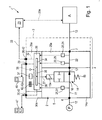
- FIG. 1 shows a schematic representation of a preferred construction of the consumer control device according to the invention with an inventive integrated compressed air maintenance device of a particularly useful structure.
- the designated in its entirety by reference numeral 1 consumer control device contains as a main component at least one preferably in the form of a self-supporting unit trained compressed air service unit 2.
- This compressed air maintenance device 2 is advantageously modular and can also, if necessary, together with other maintenance modules, one of which at 3 dash-dotted lines are summarized to a compressed air treatment device 4.
- a pressure control module and / or a filter module and / or an air drying module is present.
- the compressed air maintenance device 2 has a device housing 5, illustrated in a simplified manner as a frame, which carries the other components of the compressed air maintenance device 2 and / or contains.
- the device housing is expediently modular.
- the device inlet 6 is designed to be connected to a compressed air source P via a fluid line designated as a feed line 12. Shown is the connected to the device inlet 6 state of such a compressed air source P.
- the device outlet 7 is designed to connect to a leading to an external consumer device A, designated as working line 13 fluid line can. Shown is a state in which a consumer device A - for example, a machine having a plurality of fluid-operated working components - connected to the device outlet 7.
- the compressed air maintenance device 2 has an electrically actuated switching valve 14. This is conveniently housed inside the device housing 5 and preferably part of a valve module 14a of the modular compressed air service unit 2.
- the switching valve 14 has a 2/2-valve functionality, so has two ways or connections and two possible switching positions. In other words, it is a 2/2-way valve.
- it is of electropneumatically pilot-controlled design, but it could also be designed as a directly electrically operable valve.
- the switching valve 14 has a first switching position, which is apparent from the drawing and which is the basic position of the switching valve 14, which always is present when no electrical switching signal is applied to the switching valve 14. Based on this, it can be temporarily switched by activation of a valve drive 15a by means of an electrical switching signal in a second switching position. The second switching position remains in each case as long as the associated valve drive 15a is electrically activated.
- the electric valve drive 15a is in particular a solenoid device, although other types of electric drive means can be used.
- the switching valve 14 includes spring means 19, by which it is always biased in the direction of the basic position. If the electrical switching signal is removed while the switching valve 14 is in the second switching position, the spring means 19 switch the switching valve 14 back to the first switching position or basic position.
- the spring means 19 are preferably of a mechanical nature but can also be realized in the form of an air spring.
- the two connections of the switching valve 14 form a feed input 16 and a working output 17.
- the feed input 16 is permanently connected to the device inlet 6 via an internal inlet channel 11 of the compressed air service device 2.
- the working outlet 17 is connected via an internal outlet channel 22 of the compressed air maintenance device 2 with the device outlet 7 in connection.
- the inlet channel 11 and the outlet channel 22 expediently run in the interior of the device housing 5.
- the first switching position and therefore the basic position of the switching valve 14 is an open position.
- the open position of the working outlet 17 is fluidly connected to the feed inlet 16 and the outlet channel 22 and with this the connected consumer device A is made with compressed air supplied to the compressed air source P.
- the second switching position of the switching valve 14 is a shut-off position. In the shut-off position, the working outlet 17 is separated from the feed inlet 16, so that the outlet channel 22 is shut off and the fluid volume contained therein and in the working line 13 and the adjoining channel system of the consumer device A is locked.
- the switching valve 14 is a type of the type "normally open". When not pending electrical switching signal, the switching valve 14 always assumes the open position.
- the switching valve 14 is held during the operating times of the connected consumer device A by constantly applying the electrical switching signal in the open position. During these operating times, the consumer device A works, for example, a predetermined operating cycle once or periodically. The course of this operating cycle is expediently controlled by an external electronic control device 23, which communicates with the consumer device A in a control-related manner by schematically indicated communication means 23a, for example a field bus.
- the switching valve 14 can be switched to the shut-off position. In the case of longer periods of operation, this does not result in unnecessary air consumption possibly caused by leakage at the consumer device A.
- the switching valve 14 During only short periods of operation of the consumer device A causes a positioning of the switching valve 14 in the shut-off that the present in the consumer device A air volume is maintained and is available again for the new start of operations. This saves a complete renewed filling of the consumer device A with compressed air, which makes possible an energetically very efficient operation of the consumer device A.
- the compressed air maintenance device 2 is equipped with sensor means 20 for detecting at least one state variable of the compressed air in the system.
- sensor means 20 comprise a flow sensor 25 connected to the outlet channel 22 and preferably also a pressure sensor likewise connected to the outlet channel 22 and therefore designated as outlet pressure sensor 24.
- the sensor means 20 also contain a further pressure sensor connected to the inlet channel 11 and therefore designated as an inlet pressure sensor 31.
- the flow sensor 25 and the optional outlet pressure sensor 24 are expediently part of a sensor module 25a of the compressed air maintenance device 2.
- the optional inlet pressure sensor 31 is expediently part of a switching valve 14th containing valve module 14a.
- the flow sensor 25 is capable of determining the current flow rate of the compressed air flowing through the outlet channel 22, that is to say the flow of this compressed air. In the following, this measured flow is also referred to as outlet flow.
- the outlet pressure sensor 24 is capable of measuring the pressure prevailing in the outlet channel 22, this pressure also being referred to below as the outlet pressure.
- the inlet pressure sensor 31 is capable of to measure the pressure prevailing in the inlet duct 11 pressure, this pressure is hereinafter also referred to as inlet pressure.
- the compressed air maintenance device 2 contains a preferably housed inside the device housing 5 internal electronic control unit 26, which is equipped with at least one microprocessor or microcontroller. For the sake of simplicity, it will also be referred to below as "internal control unit 26".
- the internal control unit 26 is preferably part of a control module 26 a of the compressed air maintenance device 2.
- the internal control unit 26 is connected via internal electrical signal lines 27 of the compressed air service device 2 with the valve drive 15a of the switching valve 14, with the flow sensor 25 and, if present, with the outlet pressure sensor 24 and the inlet pressure sensor 31 signal technology.
- the internal control unit 26 may receive electrical pressure readings and flow measurements from the sensor means 20, and an electrical switch signal may output the switch valve 14 and, preferably, also electrical diagnostic signals.
- the compressed air maintenance device 2 is equipped with an electrical interface which is designated below for better distinction as the first communication interface 28 and which enables signal-technical communication between the internal control unit 26 and the external electronic control unit 23.
- the first communication interface 28 is arranged in particular on an outer side of the device housing 5 and expediently connected to the internal control unit 26 via internal electrical conductors 32.
- the first communication interface 28 is from electromechanical type and in particular designed as a plug-in interface or plug-in connection device, so that an only schematically indicated external signal cable 33 can be connected in particular releasably, which allows connection to the external electronic control device 23.
- the first communication interface 28 is preferably a bus interface capable of transmitting serial bus signals between the internal control unit 26 and the external electronic control unit 23.
- the external signal cable 33 like the internal electrical conductors 32, can be realized in the form of a serial bus system.
- the first communication interface 28 may also be designed as a wireless interface in order to be able to communicate with the external electronic control device 23 in particular via radio signals.
- the first communication interface 28 is located on the control module 26a.
- the internal control unit 26 preferably has electronic storage means 34, comparator means 35 and dispensing means 36.
- the storage means 34 may be used, for example, for pressure values relating to the outlet pressure measured by the outlet pressure sensor 24 and the inlet pressure measured by the inlet pressure sensor 31, as well as flow values of the flow sensor 25 relevant outlet flow as reference information and preferably also as actual information store.
- the comparator means 35 are able to compare stored reference information with, in particular, also cached or also directly measured actual information.
- the output means 36 are in capable of outputting at least one electrical signal as a function of the comparison result determined by the comparator means 35.
- the output means 36 are designed to output both an electrical switching signal intended for the switching valve 14 and at least one otherwise usable electrical diagnostic signal.
- the output means 36 of the internal control unit 26 issue an electrical diagnostic signal to the first communication interface 28, from where it can be transmitted to the external electronic control device 23 for further processing as required.
- At least one electrical diagnostic signal may also be supplied to optical display means 37 of the compressed air service device 2 to visualize it in any manner.
- the compressed air maintenance device 2 is equipped with only indicated by dashed lines acoustic warning means 38, such as a buzzer, so that when receiving a corresponding electrical signal on site an audible warning signal can be issued.
- acoustic warning means 38 such as a buzzer
- the internal control unit 26 can receive and process the measurement signals originating from the flow sensor 25 and optionally also from the outlet pressure sensor 24 and / or from the inlet pressure sensor 31 as actual information. In this way, the internal control unit 26 receives, as a function of time, current values of the outlet flow rate and optionally also of the outlet pressure and / or the inlet pressure as actual information.
- the internal control unit 26 may be configured to output this actual information electrically or visually on the first communication interface 28 and / or on the optical display means 37.
- the internal control unit 26 can generate at least one electrical diagnostic signal from a comparison between measured actual information with stored reference information, which provides information about the energy situation of the connected consumer device A.
- the compressed air maintenance device 2 offers, for example, the possibility of carrying out a leakage monitoring when the switching valve 14 is in the shut-off position.
- actual information supplied by the outlet pressure sensor 24 is recorded by the internal control unit 26 during the shut-off position of the switching valve 14 and compared with stored reference information.
- the internal control unit 26 initiates the output of a diagnostic signal via the output means 36, for example, when the determined pressure drop of the outlet pressure falls below the predetermined tolerance value.
- the compressed air maintenance device 2 allows a particularly advantageous flow monitoring of the outlet flow. This takes place when the switching valve 14 is in the open position. In this open position, normally compressed air flows from the compressed air source P to the consumer device A and operates there one or more activatable by fluid force working components of the consumer device A.
- These working components are, for example pneumatic drives.
- the internal control unit 26 is preferably designed such that it outputs an electrical diagnostic signal if a determined actual information deviates from the assigned reference information by a predetermined tolerance value, in particular if the air consumption differs significantly from a reference value.
- a particular advantage of the switching valve 14, which is designed as a "normally open” valve, is that it assumes the open position regardless of whether the electrical switching signal is now intentional or unintentional.
- An unintentional lack of the electrical switching signal is due for example to an unintentional power failure in the electrical power supply of the compressed air maintenance device 2.
- An intentional lack of the electrical switching signal is due, for example, to an emergency stop situation that is deliberately caused by the user of the system, or to an intentional shutdown of the power supply during commissioning or service or repair work, where an automatic lock function undesirable is. In all these situations, the compressed air supply of the connected consumer device A remains unaffected, so that failure to be attributed to uncontrollable movements of components of the consumer device A dangerous situations. Only when the power is applied again or if otherwise consciously an electrical switching signal is fed or the switching valve 14 is switched manually, a consumer device of the compressed air supply decoupling shutoff situation can be produced.
- the internal control unit 26 is designed or at least programmable or programmed in such a way that it switches the switching valve 14 from the open position into the shut-off position and in the shut-off position in addition to or alternatively to the output of at least one electrical diagnostic signal, depending on the comparison result determined by the comparator 35 can generate holding electrical switching signal.
- the internal control unit 26 generates such an electrical switchover signal, in particular, if the outlet flow value detected in the outlet duct 22 is below a predefined lower flow limit value during a predetermined time period, which is freely parameterizable in particular by input means 42 of the compressed air service device 2. Also, the lower flow limit is expediently freely parameterized by input means 42 of the compressed air maintenance device 2
- the electrical switching signal can also be used directly as a diagnostic signal itself.
- the tolerance values to be taken into account when generating a diagnostic signal or electrical switching signal are preferably input to the internal control unit 26 individually.
- the user of the compressed air maintenance device 2 can thus adapt the tolerance values and thus the signal output individually to his needs.
- the already mentioned input means 42 can be used in particular.
- the input means 42 are designed, for example, in the form of an arrangement of keys and / or switches 42a and / or for electronic input.
- the electrical interface formed by the first communication interface 28 can be used in the exemplary embodiment, which is a bus interface here, wherein the external electronic control device 23 can be used as an information input device.
- the bus interface can, for example, comply with the I / O link standard.
- the compressed air maintenance device 2 is equipped with a further, second communication interface 29, which can be used as a diagnostic interface and to which in particular an electronic information reader 46 of the consumer control device 1 is at least temporarily connectable.
- an information reader 46 makes it possible, for example, to read out measured actual information, in particular in conjunction with the assigned reference information, so that it is possible, for example in conjunction with the flow monitoring, to verify at the same time or subsequently at which point of the recorded reference profile an irregularity has occurred.
- the second communication interface 29 is in particular an Ethernet interface or another digital output. It is located, in particular, on the optional control module 26a.
- the compressed air maintenance device 2 of the embodiment contains at least one communication interface, which is designated for better distinction as the third communication interface 30 and to the conveniently an operating device and / or a personal computer (PC) can be connected ,
- the at least one third communication interface 30 is in particular an Ethernet interface or other digital input.
- the third communication interface 30 is located on a communication module 30 a of the compressed air maintenance device 2.
- the compressed air maintenance device 2 is also equipped with a communication interface, which is used for communication between the electronic control unit 26 and one or more other adjacent compressed air maintenance devices of the same or another compressed air treatment device 4.
- a communication interface which is used for communication between the electronic control unit 26 and one or more other adjacent compressed air maintenance devices of the same or another compressed air treatment device 4.
- This may be an additional communication interface not shown in the drawing or one of the communication interfaces present in the exemplary embodiment.
- the compressed air maintenance device 2 may be equipped with any other electrical interfaces for input and / or output of data and / or electrical signals.
- the compressed air maintenance device 2 When the compressed air maintenance device 2 is realized as a modular unit, it has compact dimensions and can be equipped with the desired functionality in a small space.
- the existing modules 14a, 25a, 26a and 30a can be easily assembled as needed.
Abstract
Description
Die Erfindung betrifft ein Druckluft-Wartungsgerät, das über folgende Bestandteile verfügt:
- ein elektrisch betätigbares Schaltventil, das einen mit einer Druckluftquelle verbindbaren Speiseeingang und einen Arbeitsausgang aufweist und das in eine den Arbeitsausgang mit dem Speiseeingang verbindende Offenstellung sowie in eine den Arbeitsausgang von dem Speiseeingang abtrennende Absperrstellung schaltbar ist,
- einen mit einer externen Verbrauchereinrichtung verbindbaren Geräteauslass, der über einen Auslasskanal mit dem Arbeitsausgang des Schaltventils verbunden ist,
- Sensormittel zumindest in Gestalt eines zur Messung des in dem Auslasskanal auftretenden Auslassdurchflusses dienenden Durchflusssensor,
- und eine interne elektronische Steuereinheit, die mit dem Schaltventil und mit dem Durchflusssensor signaltechnisch verbunden ist und die ausgebildet ist, um in Abhängigkeit von dem seitens des Durchflusssensors gemessenen Auslassdurchfluss ein elektrisches Umschaltsignal zu generieren, das das Schaltventil aus der Offenstellung in die Absperrstellung umschaltet.
- an electrically operable switching valve having a feed input connectable to a source of compressed air and having a working output and being switchable to an open position connecting the working output to the feed input and a shut-off position separating the working output from the feed input;
- a device outlet which can be connected to an external consumer device and which is connected to the working outlet of the switching valve via an outlet channel,
- Sensor means at least in the form of a flow sensor used to measure the outlet flow occurring in the outlet channel,
- and an internal electronic control unit, which is signal-connected to the switching valve and to the flow sensor and which is designed to generate an electrical switching signal as a function of the outlet flow measured by the flow sensor, which switches the switching valve from the open position to the shut-off position.
Die Erfindung betrifft ferner eine zur Steuerung einer Verbrauchereinrichtung geeignete Verbrauchersteuervorrichtung, die mit mindestens einem Druckluft-Wartungsgerät der vorgenannten Art und einer daran angeschlossenen oder anschließbaren elektronischen Steuereinrichtung ausgestattet ist.The invention further relates to a consumer control device suitable for controlling a consumer device, which is equipped with at least one compressed air maintenance device of the aforementioned type and an electronic control device connected or connectable thereto.
Ein in dem vorgenannten Sinne ausgebildeter Stand der Technik ist aus der
Mit Hilfe des bekannten Druckluft-Wartungsgerätes lässt sich eine Verbrauchereinrichtung sehr effizient mit Druckluft versorgen. Allerdings können seitens der angeschlossenen Verbrauchereinrichtung problematische Situationen eintreten, wenn das Schaltventil aufgrund eines unvorhergesehenen Stromausfalls oder eines sonstigen Wegfalls der elektrischen Energieversorgung in die Absperrstellung schaltet. Die Verbrauchereinrichtung ist dann von der sie speisenden Druckluft abgekoppelt, so dass auf die Druckluft angewiesene Komponenten unter Umständen unkontrollierte Bewegungen ausführen, aus denen Schäden oder gar Gefahrensituationen resultieren.With the help of the known compressed air maintenance device, a consumer device can be supplied very efficiently with compressed air. However, problematic situations may arise on the part of the connected consumer device if the switching valve switches into the shut-off position due to an unforeseen power failure or another omission of the electrical power supply. The consumer device is then decoupled from the supply of compressed air, so that the components dependent on the compressed air may perform uncontrolled movements resulting in damage or even dangerous situations.
Aus der
Die Aufgabe der vorliegenden Erfindung besteht darin, Maßnahmen zu treffen, die in Verbindung mit einem Druckluft-Wartungsgerät einen energetisch günstigen Betrieb von mit Druckluft betriebenen Verbrauchereinrichtungen ermöglichen und zugleich eine hohe Verfügbarkeit angeschlossener Verbrauchereinrichtungen in Bezug auf die Versorgung mit Druckluft sicherstellen.The object of the present invention is to take measures which, in conjunction with a compressed air maintenance device, enable an energetically favorable operation of consumer devices operated with compressed air and at the same time ensure a high availability of connected consumer devices with regard to the supply of compressed air.
Zur Lösung dieser Aufgabe ist bei einem Druckluft-Wartungsgerät der eingangs genannten Art vorgesehen, dass das Schaltventil als 2/2-Wegeventil vom Typ "Normalerweise Geöffnet" ausgebildet ist und durch Federmittel in die Offenstellung vorgespannt ist, so dass es bei fehlendem elektrischem Umschaltsignal stets die Offenstellung einnimmt.To solve this problem is provided in a compressed air maintenance device of the type mentioned that the switching valve is designed as a 2/2-way valve type "normally open" and is biased by spring means in the open position, so that it always in the absence of electrical switching signal takes the open position.
Die Aufgabe wird außerdem gelöst bei einer Verbrauchersteuervorrichtung, die über ein im vorgenannten Sinne ausgestaltetes Druckluft-Wartungsgerät und eine daran angeschlossene oder anschließbare externe elektronische Steuereinrichtung verfügt.The object is also achieved in a consumer control device, which has a configured in the aforementioned sense compressed air maintenance device and an attached or connectable external electronic control device has.
Das Druckluft-Wartungsgerät verfügt über ein als 2/2-Wegeventil des Typs "Normalerweise Geöffnet" ausgebildetes Schaltventil, das auf der Grundlage von Messwerten des Durchflusssensors aus der im Normalbetrieb eingenommenen Offenstellung in die Absperrstellung schaltbar ist, um unter gewissen Umständen einen Luftverbrauch in der nachgeschalteten externen Verbrauchereinrichtung und in dem zu dieser Verbrauchereinrichtung führenden Kanalsystem auszuschließen. Beispielsweise kann das Schaltventil in die Absperrstellung geschaltet werden, wenn die angeschlossene Verbrauchereinrichtung über einen längeren Zeitraum hinweg nicht betrieben wird. Bei fortgesetzt in der Offenstellung bleibendem Schaltventil wäre aufgrund von Leckage seitens der Verbrauchereinrichtung auch während deren Betriebsstillstand mit einem gewissen Luftverbrauch zu rechnen, der sich auf die Energiebilanz negativ auswirkt. Ergänzend dazu bietet das erfindungsgemäße Druckluft-Wartungsgerät den Vorteil, dass die Luftversorgung der angeschlossenen Verbrauchereinrichtung bei einem Stromausfall oder einem sonstigen Wegfall der für die Betätigung des Schaltventils erforderlichen elektrischen Energieversorgung nicht unterbrochen wird. Dadurch, dass das Schaltventil durch Federmittel in die Offenstellung vorgespannt ist und nur zum Umschalten und Aufrechterhalten der Absperrstellung ein elektrisches Umschaltsignal benötigt wird, wirkt sich der Ausfall des elektrischen Umschaltsignals auf die Schaltstellung des sich in der Offenstellung befindenden Schaltventils nicht aus.The compressed-air service unit has a normally-open 2/2-way valve, which can be switched to the shut-off position based on readings from the normally open position to reduce air consumption in the shut-off position downstream external consumer device and in the leading to this consumer device channel system to exclude. For example, the switching valve can be switched to the shut-off position when the connected consumer device is not operated over a longer period of time. In continuing in the open position remaining switching valve would be due to leakage on the part of the consumer device even during their downtime to be expected with a certain air consumption, which has a negative impact on the energy balance. In addition to this, the compressed air maintenance device according to the invention offers the advantage that the air supply of the connected consumer device is not interrupted in the event of a power failure or other omission of the electrical power supply required for the actuation of the switching valve. Characterized in that the switching valve is biased by spring means in the open position and only for switching and maintaining the shut-off an electrical switching signal is required, the failure of the electrical switching signal to the switching position of the located in the open position switching valve does not affect.
In der vorliegenden Beschreibung und in den Ansprüchen wird der Begriff "Durchfluss" stellvertretend und zur Vereinfachung für die an sich korrekten Begriffe wie "Volumenstrom", "Strömungsrate" oder "Durchflussrate" verwendet und bezeichnet eine Strömungsmenge pro Zeiteinheit.In the present description and in the claims, the term "flow" is used as a representative and for simplification for the correct terms such as "volume flow", "Flow rate" or "flow rate" is used and refers to a flow rate per unit of time.
Vorteilhafte Weiterbildungen der Erfindung gehen aus den Unteransprüchen hervor.Advantageous developments of the invention will become apparent from the dependent claims.
Das Druckluft-Wartungsgerät ist zweckmäßigerweise so ausgelegt, dass die interne elektronische Steuereinheit das Schaltventil aus der bis dahin eingenommenen Offenstellung in die Absperrstellung umschaltet, wenn der Durchflusssensor während der Offenstellung des Schaltventils über einen vorgegebenen oder vorgebbaren Zeitraum hinweg einen unter einem vorgegebenen oder vorgebbaren unteren Durchflussgrenzwert liegenden Durchflusswert detektiert. Auf diese Weise lässt sich eine automatische Absperrfunktion bei länger andauernder Unterschreitung eines minimalen Durchflusswertes im Auslasskanal realisieren. Auf diese Weise kann einem Druckluftverlust während Anlagenstillstandszeiten vorgebeugt werden, der leckagebedingt an der angeschlossenen Verbrauchereinrichtung auftreten kann, wenn sie ständig einem hohen Druckpotential ausgesetzt ist.The compressed air maintenance device is expediently designed so that the internal electronic control unit switches the switching valve from the previously occupied open position into the shut-off position, when the flow sensor during the open position of the switching valve over a predetermined or predeterminable period of time below a predetermined or predeterminable lower flow limit lying flow value detected. In this way, an automatic shut-off function can be realized when the minimum flow rate in the outlet channel is undershot for a longer time. In this way, a loss of compressed air during plant downtime can be prevented, which can occur due to leakage at the connected consumer device when it is constantly exposed to a high pressure potential.
Vorzugsweise enthalten die Sensormittel auch einen als Auslass-Drucksensor bezeichneten Drucksensor, der an den Auslasskanal angeschlossen ist und den darin herrschenden Auslassdruck messen kann. Mit Hilfe eines solchen Auslass-Drucksensors kann beispielsweise bei in der Absperrstellung befindlichem Schaltventil der im Auslasskanal auftretende Druckabfall pro Zeiteinheit und mithin ein eventuelles Leckageproblem ermittelt werden. Insgesamt bietet der Auslass-Drucksensor die Möglichkeit, das verbraucherseitig auftretende Druckabfallverhalten oder Druckanstiegsverhalten bei geschlossenem Schaltventil zu überwachen.Preferably, the sensor means also include a pressure sensor, referred to as outlet pressure sensor, which is connected to the outlet channel and which can measure the outlet pressure prevailing therein. With the aid of such an outlet pressure sensor, for example when the switching valve is in the shut-off position, the pressure drop occurring in the outlet channel per unit of time and consequently a possible leakage problem can be determined. Overall, the outlet pressure sensor offers the possibility of monitoring the pressure drop behavior or pressure rise behavior occurring on the consumer side with the switching valve closed.
Es ist des Weiteren von Vorteil, wenn das Druckluft-Wartungsgerät mit einem als Einlass-Drucksensor bezeichneten Drucksensor ausgestattet ist, der an einen mit dem Eingang des Schaltventils verbundenen Einlasskanal angeschlossen ist und den darin herrschenden Einlassdruck misst. Auf diese Weise ist insbesondere eine ständige Überwachung dahingehend möglich, ob einlassseitig der gewünschte Systemdruck in korrekter Höhe anliegt.It is further advantageous if the compressed air service unit is equipped with a pressure sensor, referred to as inlet pressure sensor, which is connected to an inlet channel connected to the inlet of the switching valve and measures the inlet pressure prevailing therein. In this way, in particular a constant monitoring is possible to the effect whether the inlet side of the desired system pressure is applied at the correct level.
Die interne elektronische Steuereinheit ist zweckmäßigerweise nicht nur dazu in der Lage, bedarfsgemäß das elektrische Umschaltsignal für das Schaltventil zu generieren, sondern ist insbesondere so konzipiert, dass sie mindestens ein elektrisches Diagnosesignal ausgeben kann, das unter Mitwirkung der Sensormittel, also auf der Grundlage von durch die Sensormittel erfassten Messwerten, erzeugbar ist. Beispielsweise kann ein Diagnosesignal dann ausgegeben werden, wenn durch den Durchflusssensor und/oder einen eventuell vorhandenen Drucksensor des Druckluft-Wartungsgerätes Druckluftzustände ermittelt werden, die von den im Normalbetrieb erwarteten beziehungsweise tolerierbaren Werten abweichen. Abweichende Betriebszustände können beispielsweise auf Leckage oder auf Funktionsstörungen von Komponenten der angeschlossenen externen Verbrauchereinrichtung beruhen. Zweckmäßigerweise ist mindestens ein elektrisches Diagnosesignal zusätzlich zu dem elektrischen Umschaltsignal erzeugbar. Alternativ kann aber auch vorgesehen sein, das elektrische Umschaltsignal unmittelbar selbst als Diagnosesignal zu nutzen.The internal electronic control unit is expediently not only able to generate the electrical switching signal for the switching valve as required, but is in particular designed so that it can output at least one electrical diagnostic signal, with the cooperation of the sensor means, ie on the basis of the sensor means detected measured values, can be generated. For example, a diagnostic signal can be output when compressed air conditions are determined by the flow sensor and / or a possibly existing pressure sensor of the compressed air maintenance device, which deviate from the expected or tolerable values in normal operation. Deviating operating states can be based, for example, on leakage or malfunction of components of the connected external consumer device. Conveniently, at least one electrical diagnostic signal can be generated in addition to the electrical switching signal. Alternatively, however, it may also be provided to directly use the electrical switching signal itself as a diagnostic signal.
Das Druckluft-Wartungsgerät ist zweckmäßigerweise unmittelbar mit optischen Anzeigemitteln und/oder mit akustischen Warnmitteln ausgestattet, die auf der Basis eines durch Ausgabemittel der internen elektronischen Steuereinheit erzeugten elektrischen Diagnosesignals betätigbar sind, um unmittelbar vor Ort auf problematische Betriebszustände hinzuweisen.The compressed air maintenance device is expediently equipped directly with optical display means and / or with acoustic warning means, which are generated on the basis of an output means of the internal electronic control unit electrical diagnostic signal can be actuated to indicate immediately on site to problematic operating conditions.
Das Druckluft-Wartungsgerät ist bevorzugt in Form einer modular zusammengesetzten Baueinheit ausgebildet. Die Funktionskomponenten des Gerätes sind zweckmäßigerweise in einzelnen Modulen zusammengefasst, die sich je nach gewünschtem Ausstattungsgrad in unterschiedlichen Kombinationen zusammensetzen lassen. Das Schaltventil ist zweckmäßigerweise Bestandteil eines Ventilmoduls, das bevorzugt, sofern vorhanden, auch noch den Einlass-Drucksensor beinhaltet. Der Durchflusssensor ist zweckmäßigerweise Bestandteil eines Sensormoduls, das bevorzugt, sofern vorhanden, auch noch den Auslass-Drucksensor beinhaltet. Die interne elektronische Steuereinheit schließlich ist zweckmäßigerweise Bestandteil eines Steuermoduls. Mindestens ein weiteres Modul kann als Kommunikationsmodul ausgestattet sein, das mindestens eine mit der internen elektronischen Steuereinheit verbundene Kommunikationsschnittstelle aufweist, die eine elektrische Kommunikation mit mindestens einer externen elektronischen Einrichtung ermöglicht. Auch bei nichtmodularem Aufbau ist das Druckluft-Wartungsgerät zweckmäßigerweise mit mindestens einer Kommunikationsschnittstelle zur elektrischen Kommunikation mit mindestens einer externen elektronischen Einrichtung ausgestattet.The compressed air maintenance device is preferably designed in the form of a modular assembly. The functional components of the device are expediently combined in individual modules, which can be assembled in different combinations depending on the desired degree of equipment. The switching valve is expediently part of a valve module which, if present, preferably also contains the inlet pressure sensor. The flow sensor is expediently part of a sensor module which, if present, preferably also includes the outlet pressure sensor. Finally, the internal electronic control unit is expediently part of a control module. At least one further module may be equipped as a communication module having at least one communication interface connected to the internal electronic control unit, which enables electrical communication with at least one external electronic device. Even with non-modular design, the compressed air maintenance device is expediently equipped with at least one communication interface for electrical communication with at least one external electronic device.
Bevorzugt ist das Druckluft-Wartungsgerät mit einer oder mehreren Kommunikationsschnittstellen ausgestattet, an die sich eine insbesondere als übergeordnete Steuerung fungierende externe elektronische Steuereinrichtung und/oder ein elektronisches Informationsauslesegerät und/oder ein elektronisches Informationseingabegerät und/oder mindestens eine weitere externe elektronische Einrichtung anschließen lässt beziehungsweise lassen.The compressed air maintenance device is preferably equipped with one or more communication interfaces to which an external electronic control device, in particular acting as a higher-level controller, and / or an electronic information reader and / or an electronic information input device and / or at least one further external electronic device can be connected ,
Mindestens eine Kommunikationsschnittstelle dient zweckmäßigerweise dazu, das Druckluft-Wartungsgerät in ein modulares, intern elektrisch vernetztes System mit lokalem Bussystem zu integrieren.At least one communication interface is expediently used to integrate the compressed air maintenance device into a modular, internally electrically networked system with a local bus system.
Beispielsweise ist mindestens eine Kommunikationsschnittstelle vorhanden, die als Busschnittstelle für insbesondere einen seriellen Datentransfer ausgebildet ist. Über eine solche Busschnittstelle kann die elektronische Steuereinheit des Druckluft-Wartungsgerätes mit anderen elektronischen Einrichtungen über einen Feldbus vernetzt werden.For example, at least one communication interface is provided, which is designed as a bus interface for, in particular, a serial data transfer. About such a bus interface, the electronic control unit of the compressed air maintenance device can be networked with other electronic devices via a fieldbus.
Mindestens eine Kommunikationsschnittstelle ist zweckmäßigerweise als digitaler oder analoger Eingang oder als digitaler oder analoger Ausgang konzipiert.At least one communication interface is expediently designed as a digital or analog input or as a digital or analog output.
Vorzugsweise ist das Druckluft-Wartungsgerät auch mit einer Kommunikationsschnittstelle ausgestattet, die zur Kommunikation zwischen der elektronischen Steuereinheit und einem oder mehreren weiteren Druckluft-Wartungsgeräten der gleichen oder einer anderen Druckluft-Aufbereitungsvorrichtung 4 dient.Preferably, the compressed air maintenance device is also equipped with a communication interface, which is used for communication between the electronic control unit and one or more other compressed air maintenance devices of the same or another compressed
Die Kommunikation mit externen Geräten erfolgt insbesondere drahtgebunden, kann jedoch auch drahtlos über entsprechend konzipierte Kommunikationsschnittstellen realisiert werden. Bei einer Buskommunikation können beliebige Busstandards implementiert werden.The communication with external devices is particularly wired, but can also be realized wirelessly via appropriately designed communication interfaces. In bus communication, any bus standards can be implemented.
Mindestens eine Kommunikationsschnittstelle ist zweckmäßigerweise zur bidirektionalen Signalübertragung geeignet. Außerdem ist mindestens eine Kommunikationsschnittstelle zweckmäßigerweise zur Eingabe und/oder Ausgabe binärer und/oder analoger Signale ausgebildet. Eine solche Kommunikationsschnittstelle ist zweckmäßigerweise zusätzlich zu einer als Busschnittstelle ausgebildeten Kommunikationsschnittstelle vorhanden.At least one communication interface is expediently suitable for bidirectional signal transmission. In addition, at least one communication interface is expediently designed for the input and / or output of binary and / or analog signals. Such a communication interface is expediently in addition to a bus interface trained communication interface available.
Um das Betriebsverhalten der internen elektronischen Steuereinheit und/oder der Sensormittel zu beeinflussen, ist das Druckluft-Wartungsgerät zweckmäßigerweise mit geeigneten Eingabemitteln ausgestattet. Solche Eingabemittel bestehen beispielsweise aus mindestens einer Taste und/oder mindestens einem Schalter, die außen leicht zugänglich angeordnet sind. Zusätzlich oder alternativ können auch Eingabemittel vorhanden sein, um eine rein elektrische Daten- und/oder Signaleingabe vornehmen zu können, beispielsweise über ein spezielles Bediengerät oder über eine in der Regel mit dem Druckluft-Wartungsgerät kommunizierende externe elektronische Steuereinrichtung. Solche Eingabemittel bestehen insbesondere aus mindestens einer elektrischen Kommunikationsschnittstelle.In order to influence the operating behavior of the internal electronic control unit and / or the sensor means, the compressed air maintenance device is expediently equipped with suitable input means. Such input means consist for example of at least one button and / or at least one switch, which are arranged outside easily accessible. Additionally or alternatively, input means may also be present in order to be able to carry out purely electrical data and / or signal input, for example via a special operator control device or via an external electronic control device which usually communicates with the compressed air service device. Such input means consist in particular of at least one electrical communication interface.
Die Ausstattung des Druckluft-Wartungsgerätes ermöglicht zweckmäßigerweise umfangreiche Überwachungs- und Diagnosefunktionen wie beispielsweise Vergleichsmessungen, Grenzwert-überwachungen, automatische und/oder anwendergesteuerte Verbrauchsmessungen, die Erfassung des Belüftungsvolumens und der Belüftungszeit der angeschlossenen Verbrauchereinrichtung und/oder die Ermittlung der Druckabfallzeit und der Druckabfallgeschwindigkeit in der Absperrstellung des Schaltventils.The equipment of the compressed air maintenance device expediently allows extensive monitoring and diagnostic functions such as comparative measurements, limit monitoring, automatic and / or user-controlled consumption measurements, the detection of the ventilation volume and the ventilation time of the connected consumer device and / or the determination of the pressure drop time and the pressure drop speed in the Shut-off position of the switching valve.
Zweckmäßigerweise sind in das Druckluft-Wartungsgerät Funktionen zur Messwertkomprimierung und Datenreduzierung integriert, ebenso Funktionen zur Messwertanalyse oder auch Statistikfunktionen.Expediently, functions for measuring value compression and data reduction are integrated in the compressed air maintenance device, as well as functions for measured value analysis or statistical functions.
Zweckmäßigerweise ist die interne elektronische Steuereinheit mit Speichermitteln ausgestattet, in denen Daten vielfältiger Art, insbesondere Mess-, Steuer-, Diagnose- und/oder Analysedaten, flüchtig und/oder remanent, d.h. dauerhaft auch bei Stromausfall, speicherbar sind.Conveniently, the internal electronic control unit is equipped with storage means in which data of many kinds, in particular measurement, control, diagnosis and / or analysis data, Volatile and / or remanent, ie permanently in case of power failure, can be stored.
Die Integration der internen elektronischen Steuereinheit in das Druckluft-Wartungsgerät hat den Vorteil, dass ein autonomer Betrieb des Druckluft-Wartungsgerätes möglich ist, ohne auf eine ständige Signalkommunikation mit vernetzten Geräten oder mit einer externen elektronischen Steuereinrichtung angewiesen zu sein, was die Störanfälligkeit erheblich minimiert. Gleichwohl ist selbstverständlich eine Busvernetzung und/oder die Verbindung mit einer externen elektronischen Steuereinrichtung von Vorteil, um das Betriebsverhalten auf andere Komponenten einer Anlage abstimmen zu können.The integration of the internal electronic control unit in the compressed air maintenance device has the advantage that an autonomous operation of the compressed air maintenance device is possible without having to rely on continuous signal communication with networked devices or with an external electronic control device, which significantly minimizes the susceptibility. Nevertheless, of course, a bus networking and / or the connection with an external electronic control device is advantageous in order to be able to tune the operating behavior to other components of a system.
Die zweckmäßigerweise vorhandene lokale Signalverarbeitung in der internen elektronischen Steuereinheit erlaubt eine sehr hohe Signalabtastrate und eine relativ kurze Reaktionszeit bei den Mess- und Steuerungsfunktionen, da die Transferzeiten über einen angeschlossenen Feldbus sowie Rechenzeiten in einer externen elektronischen Steuereinrichtung entfallen. Für den Transfer von Mess-, Zustands-, Steuer- und Parametrierdaten kann das Druckluft-Wartungsgerät mit Busschnittstellen aller gängigen Feldbusprotokolle ausgestattet werden.The suitably present local signal processing in the internal electronic control unit allows a very high signal sampling rate and a relatively short reaction time in the measurement and control functions, since the transfer times via a connected fieldbus and computing times in an external electronic control device omitted. For the transfer of measurement, status, control and parameter data, the compressed air service unit can be equipped with bus interfaces of all common fieldbus protocols.
Durch Wahl eines entsprechenden Ausstattungsumfanges lässt sich das Druckluft-Wartungsgerät als feldbusfähiges System mit einer elektrischen Schnittstelle zur Systemparametrierung und zur Übertragung von Mess- und Steuerdaten ausbilden. Optionale Maßnahmen zur lokalen Bedienung und Visualisierung, beispielsweise über ein optional integrierbares Display oder über ein vor Ort anschließbares Anzeige- und Bediengerät, sind ebenfalls möglich.By selecting a suitable equipment scope, the compressed air service unit can be designed as a fieldbus-capable system with an electrical interface for system parameterization and for transmission of measurement and control data. Optional measures for local operation and visualization, for example via an optionally integrable display or via a locally connectable display and operating device, are also possible.
Bei einer weiteren Ausführungsform stellt sich das Druckluft-Wartungsgerät als Stand-alone-System dar, das über mindestens einen digitalen Eingang und/oder über mindestens einen digitalen Ausgang verfügt, so dass über lokal verfügbare Mittel eine lokale Bedienung und Visualisierung durchführbar ist. Durch einen modularen Systemaufbau sind vorzugsweise folgende Einsatzvarianten realisierbar: als autonomes Einzelgerät (Stand-alone-Variante), als über Feldbus vernetzbares, selbständig arbeitendes Einzelgerät und als Funktionsmodul, das sich in Wartungsgeräte mit oder ohne Feldbusanschluss integrieren lässt.In a further embodiment, the compressed air maintenance device is a stand-alone system which has at least one digital input and / or at least one digital output, so that a local operation and visualization can be carried out via locally available means. The following application variants can preferably be implemented by means of a modular system structure: as an autonomous standalone device, as a fieldbus-networked, independently operating single device and as a function module that can be integrated in maintenance devices with or without fieldbus connection.
Nachfolgend wird die Erfindung anhand der beiliegenden Zeichnung näher erläutert. Die einzige Figur (
Die in ihrer Gesamtheit mit Bezugsziffer 1 bezeichnete Verbrauchersteuervorrichtung enthält als Hauptkomponente mindestens ein vorzugsweise in Form einer selbsttragenden Baueinheit ausgebildetes Druckluft-Wartungsgerät 2. Dieses Druckluft-Wartungsgerät 2 ist zweckmäßigerweise modular aufgebaut und kann ferner bei Bedarf zusammen mit anderen Wartungsmodulen, von denen eines bei 3 strichpunktiert angedeutet ist, zu einer Druckluft-Aufbereitungsvorrichtung 4 zusammengefasst werden. Als mindestens ein weiteres Wartungsmodul ist beispielsweise ein Druckregelmodul und/oder ein Filtermodul und/oder ein Lufttrocknungsmodul vorhanden.The designated in its entirety by reference numeral 1 consumer control device contains as a main component at least one preferably in the form of a self-supporting unit trained compressed
Das Druckluft-Wartungsgerät 2 verfügt über ein vereinfacht als Rahmen illustriertes Gerätegehäuse 5, das die weiteren Komponenten des Druckluft-Wartungsgerätes 2 trägt und/oder enthält. Das Gerätegehäuse ist zweckmäßigerweise modular aufgebaut.The compressed
Außen an dem Gerätegehäuse 5 befinden sich ein Geräteeinlass 6 und ein Geräteauslass 7, die jeweils zur Herstellung einer Fluidverbindung geeignet sind. Der Geräteeinlass 6 ist ausgebildet, um über eine als Speiseleitung 12 bezeichnete Fluidleitung mit einer Druckluftquelle P verbunden zu werden. Abgebildet ist der an den Geräteeinlass 6 angeschlossene Zustand einer solchen Druckluftquelle P.Externally on the
Der Geräteauslass 7 ist ausgebildet, um eine zu einer externen Verbrauchereinrichtung A führende, als Arbeitsleitung 13 bezeichnete Fluidleitung anschließen zu können. Gezeigt ist ein Zustand, in dem eine Verbrauchereinrichtung A - beispielsweise eine über mehrere fluidbetätigte Arbeitskomponenten verfügende Maschine - an den Geräteauslass 7 angeschlossen ist.The device outlet 7 is designed to connect to a leading to an external consumer device A, designated as working
Das Druckluft-Wartungsgerät 2 verfügt über ein elektrisch betätigbares Schaltventil 14. Dieses ist zweckmäßigerweise im Innern des Gerätegehäuses 5 untergebracht und vorzugsweise Bestandteil eines Ventilmoduls 14a des modularen Druckluft-Wartungsgerätes 2. Das Schaltventil 14 hat eine 2/2-Ventilfunktionalität, hat also zwei Wege beziehungsweise Anschlüsse und zwei mögliche Schaltstellungen. Mit anderen Worten handelt es sich bei ihm um ein 2/2-Wegeventil. Vorzugsweise ist es von elektropneumatisch vorgesteuerter Bauart, jedoch könnte es auch als direkt elektrisch betätigbares Ventil ausgebildet sein.The compressed
Das Schaltventil 14 hat eine erste Schaltstellung, die aus der Zeichnung ersichtlich ist und bei der es sich um die Grundstellung das Schaltventil 14 handelt, die immer dann vorliegt, wenn an dem Schaltventil 14 kein elektrisches Umschaltsignal anliegt. Ausgehend hiervon kann es durch Aktivierung eines Ventilantriebes 15a mittels eines elektrischen Umschaltsignals zeitweilig in eine zweite Schaltstellung umgeschaltet werden. Die zweite Schaltstellung bleibt jeweils so lange bestehen, wie der zugeordnete Ventilantrieb 15a elektrisch aktiviert ist. Bei dem elektrischen Ventilantrieb 15a handelt es sich insbesondere um eine Elektromagneteinrichtung, wobei allerdings auch andere Arten elektrischer Antriebsmittel verwendbar sind.The switching
Das Schaltventil 14 enthält Federmittel 19, durch die es ständig in Richtung der Grundstellung vorgespannt ist. Wird das elektrische Umschaltsignal entfernt, während sich das das Schaltventil 14 in der zweiten Schaltstellung befindet, schalten die Federmittel 19 das Schaltventil 14 in die erste Schaltstellung bzw. Grundstellung zurück. Die Federmittel 19 sind bevorzugt mechanischer Art können allerdings auch in Form einer Luftfeder realisiert sein.The switching
Die beiden Anschlüsse des Schaltventils 14 bilden einen Speiseeingang 16 und einen Arbeitsausgang 17. Der Speiseeingang 16 ist über einen internen Einlasskanal 11 des Druckluft-Wartungsgerätes 2 ständig mit dem Geräteeinlass 6 verbunden. Der Arbeitsausgang 17 steht über einen internen Auslasskanal 22 des Druckluft-Wartungsgerätes 2 mit dem Geräteauslass 7 in Verbindung. Der Einlasskanal 11 und der Auslasskanal 22 verlaufen zweckmäßigerweise im Innern des Gerätegehäuses 5.The two connections of the switching
Die erste Schaltstellung und mithin die Grundstellung des Schaltventils 14 ist eine Offenstellung. In der Offenstellung ist der Arbeitsausgang 17 mit dem Speiseeingang 16 fluidisch verbunden und der Auslasskanal 22 und mit diesem die angeschlossene Verbrauchereinrichtung A wird mit Druckluft aus der Druckluftquelle P versorgt. Die zweite Schaltstellung des Schaltventils 14 ist eine Absperrstellung. In der Absperrstellung ist der Arbeitsausgang 17 von dem Speiseeingang 16 abgetrennt, sodass der Auslasskanal 22 abgesperrt und das darin sowie in der Arbeitsleitung 13 und dem sich daran anschließenden Kanalsystem der Verbrauchereinrichtung A befindliche Fluidvolumen eingesperrt ist.The first switching position and therefore the basic position of the switching
Bedingt durch die oben erwähnten Federmittel 19 ergibt sich für das Schaltventil 14 eine Bauart vom Typ "Normalerweise Geöffnet". Bei nicht anstehendem elektrischem Umschaltsignal nimmt das Schaltventil 14 stets die Offenstellung ein.Due to the above-mentioned spring means 19 results for the switching
Das Schaltventil 14 wird während der Betriebszeiten der angeschlossenen Verbrauchereinrichtung A durch ständiges Anlegen des elektrischen Umschaltsignals in der Offenstellung gehalten. Während dieser Betriebszeiten arbeitet die Verbrauchereinrichtung A beispielsweise einen vorgegebenen Betriebszyklus einmalig oder periodisch ab. Der Ablauf dieses Betriebszyklus wird zweckmäßigerweise durch eine externe elektronische Steuereinrichtung 23 gesteuert, die durch schematisch angedeutete Kommunikationsmittel 23a, zum Beispiel ein Feldbus, in steuerungstechnischer Hinsicht mit der Verbrauchereinrichtung A kommuniziert.The switching
Soll die Verbrauchereinrichtung A nicht betrieben werden, beispielsweise während Betriebspausen, kann das Schaltventil 14 in die Absperrstellung geschaltet werden. Bei längeren Betriebspausen tritt dadurch kein unnötiger, eventuell durch Leckage an der Verbrauchereinrichtung A verursachter Luftverbrauch auf. Während nur kurzzeitiger Betriebspausen der Verbrauchereinrichtung A bewirkt eine Positionierung des Schaltventil 14 in der Absperrstellung, dass das in der Verbrauchereinrichtung A vorhandene Luftvolumen erhalten bleibt und für die neuerliche Betriebsaufnahme wieder zur Verfügung steht. Man erspart sich somit ein erneutes komplettes Befüllen der Verbrauchereinrichtung A mit Druckluft, was einen energetisch sehr effizienten Betrieb der Verbrauchereinrichtung A ermöglicht.If the consumer device A is not to be operated, for example during pauses in operation, the switching
Das Druckluft-Wartungsgerät 2 ist mit Sensormitteln 20 zur Erfassung mindestens einer Zustandsgröße der im System befindlichen Druckluft ausgestattet. Diese Sensormittel 20 enthalten einen an den Auslasskanal 22 angeschlossenen Durchflusssensor 25 und vorzugsweise auch noch einen ebenfalls an den Auslasskanal 22 angeschlossenen und deshalb als Auslass-Drucksensor 24 bezeichneten Drucksensor.The compressed
Optional und vorzugsweise enthalten die Sensormittel 20 auch noch einen an den Einlasskanal 11 angeschlossenen und deshalb als Einlass-Drucksensor 31 bezeichneten weiteren Drucksensor.Optionally and preferably, the sensor means 20 also contain a further pressure sensor connected to the
Alle Sensormittel 20 befinden sich zweckmäßigerweise im Innern des Gerätegehäuses 5. Der Durchflusssensor 25 und der optional vorhandene Auslass-Drucksensor 24 sind zweckmäßigerweise Bestandteil eines Sensormoduls 25a des Druckluft-Wartungsgerätes 2. Der optional vorhandene Einlass-Drucksensor 31 ist zweckmäßigerweise Bestandteil eines auch das Schaltventil 14 enthaltenden Ventilmoduls 14a.The flow sensor 25 and the optional outlet pressure sensor 24 are expediently part of a
Der Durchflusssensor 25 ist in der Lage, die aktuelle Strömungsrate der durch den Auslasskanal 22 hindurchströmenden Druckluft, also den Durchfluss dieser Druckluft, zu ermitteln. Im Folgenden sei dieser gemessene Durchfluss auch als Auslassdurchfluss bezeichnet. Der Auslass-Drucksensor 24 ist in der Lage, den im Auslasskanal 22 herrschenden Druck zu messen, wobei dieser Druck im Folgenden auch als Auslassdruck bezeichnet sei. Der Einlass-Drucksensor 31 ist in der Lage, den im Einlasskanal 11 herrschenden Druck zu messen, wobei dieser Druck im Folgenden auch als Einlassdruck bezeichnet sei.The flow sensor 25 is capable of determining the current flow rate of the compressed air flowing through the
Das Druckluft-Wartungsgerät 2 enthält eine bevorzugt im Innern des Gerätegehäuses 5 untergebrachte interne elektronische Steuereinheit 26, die mit mindestens einem Mikroprozessor beziehungsweise Mikrocontroller ausgestattet ist. Zur Vereinfachung sei sie im Folgenden auch nur als "interne Steuereinheit 26" bezeichnet. Die interne Steuereinheit 26 ist bevorzugt Bestandteil eines Steuermoduls 26a des Druckluft-Wartungsgerätes 2.The compressed
Die interne Steuereinheit 26 ist über interne elektrische Signalleitungen 27 des Druckluft-Wartungsgerätes 2 mit dem Ventilantrieb 15a des Schaltventils 14, mit dem Durchflusssensor 25 und, sofern vorhanden, mit dem Auslass-Drucksensor 24 und dem Einlass-Drucksensor 31 signaltechnisch verbunden. Die interne Steuereinheit 26 kann elektrische Druckmesswerte und Durchflussmesswerte von den Sensormitteln 20 empfangen und kann ein elektrisches Umschaltsignal das Schaltventil 14 sowie, vorzugsweise, auch noch elektrische Diagnosesignale ausgeben.The
Das Druckluft-Wartungsgerät 2 ist mit einer im Folgenden zur besseren Unterscheidung als erste Kommunikationsschnittstelle 28 bezeichneten elektrischen Schnittstelle ausgestattet, die eine signaltechnische Kommunikation zwischen der internen Steuereinheit 26 und der externen elektronischen Steuereinrichtung 23 ermöglicht. Die erste Kommunikationsschnittstelle 28 ist insbesondere an einer Außenseite des Gerätegehäuses 5 angeordnet und zweckmäßigerweise über interne elektrische Leiter 32 mit der internen Steuereinheit 26 verbunden. Vorzugsweise ist die erste Kommunikationsschnittstelle 28 von elektromechanischer Art und insbesondere als Steckschnittstelle bzw. Steckanschlusseinrichtung konzipiert, so dass sich ein nur schematisch angedeutetes externes Signalkabel 33 insbesondere lösbar anschließen lässt, das eine Verbindung zu der externen elektronischen Steuereinrichtung 23 ermöglicht.The compressed
Bei der ersten Kommunikationsschnittstelle 28 handelt es sich vorzugsweise um eine Busschnittstelle, die in der Lage ist, serielle Bussignale zwischen der internen Steuereinheit 26 und der externen elektronischen Steuereinrichtung 23 zu übertragen. Das externe Signalkabel 33 kann ebenso wie die internen elektrischen Leiter 32 in Form eines seriellen Bussystems realisiert sein.The first communication interface 28 is preferably a bus interface capable of transmitting serial bus signals between the
Alternativ kann die erste Kommunikationsschnittstelle 28 auch als drahtlos arbeitende Schnittstelle konzipiert sein, um insbesondere über Funksignale mit der externen elektronischen Steuereinrichtung 23 kommunizieren zu können.Alternatively, the first communication interface 28 may also be designed as a wireless interface in order to be able to communicate with the external
Bevorzugt befindet sich die erste Kommunikationsschnittstelle 28 an dem Steuermodul 26a.Preferably, the first communication interface 28 is located on the
Die interne Steuereinheit 26 verfügt bevorzugt über elektronische Speichermittel 34, über Vergleichermittel 35 und über Ausgabemittel 36. In den Speichermitteln 34 lassen sich beispielsweise Druckwerte betreffend den vom Auslass-Drucksensor 24 gemessenen Auslassdruck und den vom Einlass-Drucksensor 31 gemessenen Einlassdruck sowie Durchflusswerte des den Durchflusssensor 25 betreffenden Auslassdurchflusses als Referenzinformationen und vorzugsweise auch als Ist-Informationen abspeichern. Die Vergleichermittel 35 sind in der Lage, gespeicherte Referenzinformationen mit insbesondere ebenfalls zwischengespeicherten oder auch mit unmittelbar gemessenen Ist-Informationen zu vergleichen. Die Ausgabemittel 36 sind in der Lage, in Abhängigkeit von dem durch die Vergleichermittel 35 ermittelten Vergleichsergebnis mindestens ein elektrisches Signal auszugeben. Exemplarisch sind die Ausgabemittel 36 ausgebildet, um sowohl ein für das Schaltventil 14 bestimmtes elektrisches Umschaltsignal als auch mindestens ein anderweitig verwertbares elektrisches Diagnosesignal auszugeben.The
Vorzugsweise geben die Ausgabemittel 36 der internen Steuereinheit 26 ein elektrische Diagnosesignal an die erste Kommunikationsschnittstelle 28 aus, von wo aus es zur bedarfsgemäßen weiteren Verarbeitung an die externe elektronische Steuereinrichtung 23 übermittelbar ist.Preferably, the output means 36 of the
Mindestens ein elektrisches Diagnosesignal kann auch optischen Anzeigemitteln 37 des Druckluft-Wartungsgerätes 2 zugeleitet werden, um es in beliebiger Weise zu visualisieren.At least one electrical diagnostic signal may also be supplied to optical display means 37 of the compressed
Es ist ferner möglich, dass das Druckluft-Wartungsgerät 2 mit nur gestrichelt angedeuteten akustischen Warnmitteln 38 ausgestattet ist, beispielsweise ein Summer, so dass bei Empfang eines entsprechenden elektrischen Signals vor Ort ein akustisches Warnsignal ausgegeben werden kann.It is also possible that the compressed
Die interne Steuereinheit 26 kann während ihres Betriebes von dem Durchflusssensor 25 sowie optional auch von dem Auslass-Drucksensor 24 und/oder von dem Einlass-Drucksensor 31 stammende Messsignale als Ist-Informationen empfangen und verarbeiten. Auf diese Weise empfängt die interne Steuereinheit 26 zeitabhängig aktuelle Werte des Auslassdurchflusses sowie gegebenenfalls auch des Auslassdruckes und/oder des Einlassdruckes als Ist-Informationen. Die interne Steuereinheit 26 kann ausgebildet sein, um diese Ist-Informationen an der ersten Kommunikationsschnittstelle 28 und/oder an den optischen Anzeigemitteln 37 elektrisch oder visuell auszugeben.During operation, the
Im Betrieb der Verbrauchersteuervorrichtung 1 kann die interne Steuereinheit 26 aus einem Vergleich zwischen gemessenen Ist-Informationen mit gespeicherten Referenzinformationen mindestens ein elektrisches Diagnosesignal generieren, das Aufschluss über die energetische Situation der angeschlossenen Verbrauchereinrichtung A liefert.During operation of the consumer control device 1, the
Das Druckluft-Wartungsgerät 2 bietet beispielsweise die Möglichkeit, bei in Absperrstellung befindlichem Schaltventil 14 eine Leckage-Überwachung vorzunehmen. Hierzu werden durch die interne Steuereinheit 26 während der Absperrstellung des Schaltventils 14 von dem Auslass-Drucksensor 24 gelieferte Ist-Informationen aufgezeichnet und mit abgespeicherten Referenzinformationen verglichen. Die interne Steuereinheit 26 veranlasst über die Ausgabemittel 36 beispielsweise dann die Ausgabe eines Diagnosesignals, wenn der ermittelte Druckabfall des Auslassdruckes den um einen vorgegebenen Toleranzwert unterschreitet.The compressed
Ebenso wie bei der Überwachung des Auslassdruckes kann auch bei der Überwachung des Ausgangsdurchflusses eine nur einmalige oder aber eine mehrmalige Aufzeichnung von Ist-Informationen stattfinden, wobei eine mehrmalige Aufzeichnung von Ist-Informationen insbesondere in zeitlicher Regelmäßigkeit stattfinden kann.As in the case of monitoring the outlet pressure, it is also possible to record actual information only once or several times during the monitoring of the output flow, wherein a repeated recording of actual information can take place, in particular with temporal regularity.
Das Druckluft-Wartungsgerät 2 ermöglicht eine besonders vorteilhafte Durchflussüberwachung des Auslassdurchflusses. Diese findet bei in der Offenstellung befindlichem Schaltventil 14 statt. In dieser Offenstellung strömt normalerweise Druckluft aus der Druckluftquelle P zur Verbrauchereinrichtung A und betätigt dort eine oder mehrere mittels Fluidkraft aktivierbare Arbeitskomponenten der Verbrauchereinrichtung A. Eine oder mehrere dieser Arbeitskomponenten sind beispielsweise pneumatische Antriebe. Durch einen Vergleich der erfassten Auslassdurchfluss-Ist-Informationen mit gespeicherten referenzwerten lässt sich sehr einfach überwachen, ob während des Betriebszyklus oder während bestimmter Phasen beziehungsweise Teilzyklen des Betriebszyklus ein erhöhter Luftverbrauch auftritt, was ein Anzeichen für Funktionsstörungen oder fehlerhafte Arbeitskomponenten ist.The compressed
Auch bei der Durchflussüberwachung ist die interne Steuereinheit 26 bevorzugt so ausgebildet, dass sie ein elektrisches Diagnosesignal ausgibt, wenn eine ermittelte Ist-Information um einen vorgegebenen Toleranzwert von der zugeordneten Referenzinformation abweicht, insbesondere bei einem von einem Referenzwert erheblich abweichenden Luftverbrauch.Even in the case of flow monitoring, the
Ein besonderer Vorteil des als "Normalerweise Geöffnet"-Ventil ausgebildeten Schaltventils 14 besteht darin, dass es die Offenstellung unabhängig davon einnimmt, ob das elektrische Umschaltsignal nun beabsichtigt oder unbeabsichtigt nicht ansteht. Ein unbeabsichtigtes Fehlen des elektrischen Umschaltsignals ist beispielsweise auf einen unbeabsichtigten Stromausfall in der elektrischen Energieversorgung des Druckluft-Wartungsgerätes 2 zurückzuführen. Ein beabsichtigtes Fehlen des elektrischen Umschaltsignals ist beispielsweise zurückzuführen auf eine Not-Aus-Situation, die vom Nutzer der Anlage bewusst hervorgerufen wird, oder auf ein beabsichtigtes Abschalten der Stromversorgung bei einer Inbetriebnahme oder bei Service- bzw. Instandsetzungsarbeiten, bei denen eine automatische Sperrfunktion unerwünscht ist. In all diesen Situationen bleibt die Druckluftversorgung der angeschlossenen Verbrauchereinrichtung A unbeeinflusst, so dass auf unkontrollierbare Bewegungen von Komponenten der Verbrauchereinrichtung A zurückzuführende Gefahrensituationen ausbleiben. Erst wenn die Stromversorgung wieder anliegt oder wenn anderweitig bewusst ein elektrisches Umschaltsignal eingespeist wird oder das Schaltventil 14 manuell umgeschaltet wird, ist eine die Verbrauchereinrichtung von der Druckluftversorgung abkoppelnde Absperrsituation herstellbar.A particular advantage of the switching
Die interne Steuereinheit 26 ist derart ausgelegt oder zumindest programmierbar bzw. programmiert, dass sie in Abhängigkeit von dem durch die Vergleichermittel 35 festgestellten Vergleichsergebnis zusätzlich oder alternativ zur Ausgabe mindestens eines elektrischen Diagnosesignals ein das Schaltventil 14 aus der Offenstellung in die Absperrstellung umschaltendes und in der Absperrstellung haltendes elektrisches Umschaltsignal erzeugen kann. Die interne Steuereinheit 26 erzeugt ein solches elektrisches Umschaltsignal insbesondere dann, wenn während eines vorgegebenen Zeitraumes, der insbesondere durch Eingabemittel 42 des Druckluft-Wartungsgerätes 2 frei parametrierbar ist, der in dem Auslasskanal 22 detektierte Auslassdurchflusswert unterhalb eines vorgegebenen unteren Durchflussgrenzwertes liegt. Auch der untere Durchflussgrenzwert ist zweckmäßigerweise durch Eingabemittel 42 des Druckluft-Wartungsgerätes 2 frei parametrierbarThe
Es versteht sich, dass das elektrische Umschaltsignal auch unmittelbar selbst als Diagnosesignal genutzt werden kann.It is understood that the electrical switching signal can also be used directly as a diagnostic signal itself.
Die bei der Generierung eines Diagnosesignals oder elektrischen Umschaltsignals zu berücksichtigenden Toleranzwerte sind vorzugsweise individuell in die interne Steuereinheit 26 eingebbar. Der Nutzer des Druckluft-Wartungsgerätes 2 kann somit die Toleranzwerte und mithin die Signalausgabe individuell an seine Bedürfnisse anpassen. Zur Eingabe der Toleranzwerte können insbesondere die schon erwähnten Eingabemittel 42 genutzt werden.The tolerance values to be taken into account when generating a diagnostic signal or electrical switching signal are preferably input to the
Die Eingabemittel 42 sind beispielsweise in Form eine Anordnung von Tasten und/oder Schaltern 42a und/oder zur elektronischen Eingabe ausgebildet. Zur elektronischen Eingabe ist beim Ausführungsbeispiel die von der ersten Kommunikationsschnittstelle 28 gebildete elektrische Schnittstelle nutzbar, die hier eine Busschnittstelle ist, wobei die externe elektronische Steuereinrichtung 23 als Informationseingabegerät verwendbar ist. Die Busschnittstelle kann beispielsweise dem I/O-Link-Standard entsprechen.The input means 42 are designed, for example, in the form of an arrangement of keys and / or switches 42a and / or for electronic input. For electronic input, the electrical interface formed by the first communication interface 28 can be used in the exemplary embodiment, which is a bus interface here, wherein the external
Beim Ausführungsbeispiel ist das Druckluft-Wartungsgerät 2 mit einer weiteren, zweiten Kommunikationsschnittstelle 29 ausgestattet, die als Diagnoseschnittstelle nutzbar ist und an der insbesondere ein elektronisches Informationsauslesegerät 46 der Verbrauchersteuervorrichtung 1 zumindest zeitweilig anschließbar ist. Ein solches Informationsauslesegerät 46 ermöglicht beispielsweise das Auslesen gemessener Ist-Informationen, insbesondere in Verbindung mit den zugeordneten Referenzinformationen, so dass sich beispielsweise in Verbindung mit der Durchflussüberwachung zeitgleich oder auch noch nachträglich verifizieren lässt, an welcher Stelle des aufgezeichneten Referenzprofils eine Unregelmäßigkeit aufgetreten ist. Die zweite Kommunikationsschnittstelle 29 ist insbesondere eine Ethernet-Schnittstelle oder ein sonstiger digitaler Ausgang. Sie befindet sich insbesondere an dem gegebenenfalls vorhandenen Steuermodul 26a.In the exemplary embodiment, the compressed
Als weitere Eingabemittel 42 zur elektronischen Dateneingabe zwecks Konfiguration des Systems enthält das Druckluft-Wartungsgerät 2 des Ausführungsbeispiels mindestens eine Kommunikationsschnittstelle, die zur besseren Unterscheidung als dritte Kommunikationsschnittstelle 30 bezeichnet sei und an die zweckmäßigerweise ein Bediengerät und/oder ein Personalcomputer (PC) angeschlossen werden kann. Die mindestens eine dritte Kommunikationsschnittstelle 30 ist insbesondere eine Ethernet-Schnittstelle oder ein sonstiger digitaler Eingang. Bevorzugt befindet sich die dritte Kommunikationsschnittstelle 30 an einem Kommunikationsmodul 30a des Druckluft-Wartungsgeräts 2.As a further input means 42 for electronic data input for the purpose of configuration of the system, the compressed
Vorzugsweise ist das Druckluft-Wartungsgerät 2 auch mit einer Kommunikationsschnittstelle ausgestattet, die zur Kommunikation zwischen der elektronischen Steuereinheit 26 und einem oder mehreren weiteren benachbarten Druckluft-Wartungsgeräten der gleichen oder einer anderen Druckluft-Aufbereitungsvorrichtung 4 dient. Es kann sich hierbei um eine in der Zeichnung nicht abgebildete zusätzliche Kommunikationsschnittstelle handeln oder um eine der beim Ausführungsbeispiel vorhandenen Kommunikationsschnittstellen.Preferably, the compressed
Es versteht sich, dass das Druckluft-Wartungsgerät 2 mit beliebigen weiteren elektrischen Schnittstellen zur Eingabe und/oder Ausgabe von Daten und/oder elektrischen Signalen ausgestattet sein kann.It is understood that the compressed
Wenn das Druckluft-Wartungsgerät 2 als modulare Baueinheit realisiert ist, verfügt es über kompakte Abmessungen und kann auf wenig Raum mit der gewünschten Funktionalität ausgestattet werden. Die vorhandenen Module 14a, 25a, 26a und 30a können nach Bedarf leicht zusammengesetzt werden.When the compressed
Claims (15)
dadurch gekennzeichnet,
characterized,
Applications Claiming Priority (1)
| Application Number | Priority Date | Filing Date | Title |
|---|---|---|---|
| DE102012021533.9A DE102012021533A1 (en) | 2012-10-31 | 2012-10-31 | Compressed air maintenance device and thus equipped consumer control device |
Publications (3)
| Publication Number | Publication Date |
|---|---|
| EP2728205A2 true EP2728205A2 (en) | 2014-05-07 |
| EP2728205A3 EP2728205A3 (en) | 2017-12-06 |
| EP2728205B1 EP2728205B1 (en) | 2020-10-14 |
Family
ID=48808145
Family Applications (1)
| Application Number | Title | Priority Date | Filing Date |
|---|---|---|---|
| EP13003650.2A Active EP2728205B1 (en) | 2012-10-31 | 2013-07-20 | Compressed air maintenance unit, and consumer control device equipped with the same |
Country Status (2)
| Country | Link |
|---|---|
| EP (1) | EP2728205B1 (en) |
| DE (1) | DE102012021533A1 (en) |
Cited By (2)
| Publication number | Priority date | Publication date | Assignee | Title |
|---|---|---|---|---|
| DE102018202416A1 (en) | 2018-02-16 | 2019-08-22 | Festo Ag & Co. Kg | Consumer control device and control method |
| CN112673237A (en) * | 2018-10-15 | 2021-04-16 | 威科生产有限公司 | Intelligent measuring instrument |
Families Citing this family (1)
| Publication number | Priority date | Publication date | Assignee | Title |
|---|---|---|---|---|
| IT202000012010A1 (en) * | 2020-05-22 | 2021-11-22 | Safen Fluid & Mech Engineering S R L | DEVICE FOR THE DIAGNOSTICS OF PNEUMATIC SYSTEMS |
Citations (2)
| Publication number | Priority date | Publication date | Assignee | Title |
|---|---|---|---|---|
| DE102009016069B3 (en) | 2009-04-03 | 2010-12-16 | Festo Ag & Co. Kg | Method for saving compressed air in pneumatic mechanism, involves delivering lock signal to lock for locking air supply, or for resetting timing element if actual interval is smaller than reference interval |
| DE102011012558B3 (en) | 2011-02-26 | 2012-07-12 | Festo Ag & Co. Kg | Compressed air maintenance device and thus equipped consumer control device |
Family Cites Families (2)
| Publication number | Priority date | Publication date | Assignee | Title |
|---|---|---|---|---|
| DE102005057004B3 (en) * | 2005-11-30 | 2007-04-05 | Knorr-Bremse Systeme für Nutzfahrzeuge GmbH | Compressed air preparation device for brake force adjusting system of commercial vehicle, has excited first solenoid controlled valve, with which pressure essentially remains in a line between compressor and stop valve |
| DE102007005987B4 (en) * | 2007-02-07 | 2010-09-09 | Knorr-Bremse Systeme für Nutzfahrzeuge GmbH | Valve device for a compressed air supply device and compressed air supply system |
-
2012
- 2012-10-31 DE DE102012021533.9A patent/DE102012021533A1/en not_active Withdrawn
-
2013
- 2013-07-20 EP EP13003650.2A patent/EP2728205B1/en active Active
Patent Citations (2)
| Publication number | Priority date | Publication date | Assignee | Title |
|---|---|---|---|---|
| DE102009016069B3 (en) | 2009-04-03 | 2010-12-16 | Festo Ag & Co. Kg | Method for saving compressed air in pneumatic mechanism, involves delivering lock signal to lock for locking air supply, or for resetting timing element if actual interval is smaller than reference interval |
| DE102011012558B3 (en) | 2011-02-26 | 2012-07-12 | Festo Ag & Co. Kg | Compressed air maintenance device and thus equipped consumer control device |
Cited By (3)
| Publication number | Priority date | Publication date | Assignee | Title |
|---|---|---|---|---|
| DE102018202416A1 (en) | 2018-02-16 | 2019-08-22 | Festo Ag & Co. Kg | Consumer control device and control method |
| US10731679B2 (en) | 2018-02-16 | 2020-08-04 | Festo Se & Co. Kg | Consumer control device and a control method |
| CN112673237A (en) * | 2018-10-15 | 2021-04-16 | 威科生产有限公司 | Intelligent measuring instrument |
Also Published As
| Publication number | Publication date |
|---|---|
| EP2728205A3 (en) | 2017-12-06 |
| DE102012021533A1 (en) | 2014-04-30 |
| EP2728205B1 (en) | 2020-10-14 |
Similar Documents
| Publication | Publication Date | Title |
|---|---|---|
| EP2622229B1 (en) | Compressed air maintenance unit, and consumer control device equipped with the same | |
| EP2024712B1 (en) | Device for transmitting measured values | |
| DE102012021387B3 (en) | Electropneumatic field device and electropneumatic assembly | |
| EP3546763B1 (en) | Detection of maintenance conditions of valves | |
| DE102008060010A1 (en) | Safety control and method for controlling an automated plant | |
| EP2545417B1 (en) | Method for replacing an existing control device in an automation system with a new control device and automation system designed for this purpose | |
| DE102018202416A1 (en) | Consumer control device and control method | |
| EP2387523B1 (en) | Method for operating a hydraulic or pneumatic system | |
| DE102014206308B4 (en) | Handling system and method for operating a handling system | |
| DE102008038723B3 (en) | Method and device for controlling an electropneumatic valve of a pressure-medium-actuated positioner | |
| WO2010060572A1 (en) | Safety control and method for controlling an automated system | |
| EP3516218B1 (en) | Compressor system for a work vehicle | |
| DE112008003195T5 (en) | Electrical circuit with a physical transmission layer diagnostic system | |
| EP2865899B1 (en) | Compressed air maintenance unit, consumption control device equipped with the same and associated operating method | |
| DE10052664B4 (en) | Process monitoring device | |
| WO2001059307A1 (en) | Fluidic system with a safety function | |
| DE10222890B4 (en) | Electrical device for controlling a multi-way valve with wear condition detection | |
| EP2728205B1 (en) | Compressed air maintenance unit, and consumer control device equipped with the same | |
| EP3289229B1 (en) | Valve arrangement | |
| DE202013011331U1 (en) | Valve module and valve terminal | |
| DE102012016269A1 (en) | Electric machine with a monitoring device | |
| EP3644020B1 (en) | Compressed air compressor system with sensor unit | |
| DE102011101398B4 (en) | Compressed air maintenance unit | |
| EP2617381B1 (en) | Air supply system for medical applications and method for operating same | |
| DE102009011242B4 (en) | Limit switch and method for operating a limit switch |
Legal Events
| Date | Code | Title | Description |
|---|---|---|---|
| PUAI | Public reference made under article 153(3) epc to a published international application that has entered the european phase |
Free format text: ORIGINAL CODE: 0009012 |
|
| 17P | Request for examination filed |
Effective date: 20130720 |
|
| AK | Designated contracting states |
Kind code of ref document: A2 Designated state(s): AL AT BE BG CH CY CZ DE DK EE ES FI FR GB GR HR HU IE IS IT LI LT LU LV MC MK MT NL NO PL PT RO RS SE SI SK SM TR |
|
| AX | Request for extension of the european patent |
Extension state: BA ME |
|
| PUAL | Search report despatched |
Free format text: ORIGINAL CODE: 0009013 |
|
| AK | Designated contracting states |
Kind code of ref document: A3 Designated state(s): AL AT BE BG CH CY CZ DE DK EE ES FI FR GB GR HR HU IE IS IT LI LT LU LV MC MK MT NL NO PL PT RO RS SE SI SK SM TR |
|
| AX | Request for extension of the european patent |
Extension state: BA ME |
|
| RIC1 | Information provided on ipc code assigned before grant |
Ipc: F15B 21/04 20060101AFI20171031BHEP |
|
| STAA | Information on the status of an ep patent application or granted ep patent |
Free format text: STATUS: REQUEST FOR EXAMINATION WAS MADE |
|
| 17P | Request for examination filed |
Effective date: 20180522 |
|
| RBV | Designated contracting states (corrected) |
Designated state(s): AL AT BE BG CH CY CZ DE DK EE ES FI FR GB GR HR HU IE IS IT LI LT LU LV MC MK MT NL NO PL PT RO RS SE SI SK SM TR |
|
| RAP1 | Party data changed (applicant data changed or rights of an application transferred) |
Owner name: FESTO SE & CO. KG |
|
| GRAP | Despatch of communication of intention to grant a patent |
Free format text: ORIGINAL CODE: EPIDOSNIGR1 |
|
| STAA | Information on the status of an ep patent application or granted ep patent |
Free format text: STATUS: GRANT OF PATENT IS INTENDED |
|
| INTG | Intention to grant announced |
Effective date: 20200602 |
|
| RIN1 | Information on inventor provided before grant (corrected) |
Inventor name: MAYER, ANDREAS Inventor name: GARNER, JENS |
|
| GRAS | Grant fee paid |
Free format text: ORIGINAL CODE: EPIDOSNIGR3 |
|
| GRAA | (expected) grant |
Free format text: ORIGINAL CODE: 0009210 |
|
| STAA | Information on the status of an ep patent application or granted ep patent |
Free format text: STATUS: THE PATENT HAS BEEN GRANTED |
|
| AK | Designated contracting states |
Kind code of ref document: B1 Designated state(s): AL AT BE BG CH CY CZ DE DK EE ES FI FR GB GR HR HU IE IS IT LI LT LU LV MC MK MT NL NO PL PT RO RS SE SI SK SM TR |
|
| REG | Reference to a national code |
Ref country code: GB Ref legal event code: FG4D Free format text: NOT ENGLISH |
|
| REG | Reference to a national code |
Ref country code: AT Ref legal event code: REF Ref document number: 1323884 Country of ref document: AT Kind code of ref document: T Effective date: 20201015 Ref country code: CH Ref legal event code: EP |
|
| REG | Reference to a national code |
Ref country code: DE Ref legal event code: R096 Ref document number: 502013015201 Country of ref document: DE |
|
| REG | Reference to a national code |
Ref country code: IE Ref legal event code: FG4D Free format text: LANGUAGE OF EP DOCUMENT: GERMAN |
|
| REG | Reference to a national code |
Ref country code: NL Ref legal event code: MP Effective date: 20201014 |
|
| PG25 | Lapsed in a contracting state [announced via postgrant information from national office to epo] |
Ref country code: FI Free format text: LAPSE BECAUSE OF FAILURE TO SUBMIT A TRANSLATION OF THE DESCRIPTION OR TO PAY THE FEE WITHIN THE PRESCRIBED TIME-LIMIT Effective date: 20201014 Ref country code: RS Free format text: LAPSE BECAUSE OF FAILURE TO SUBMIT A TRANSLATION OF THE DESCRIPTION OR TO PAY THE FEE WITHIN THE PRESCRIBED TIME-LIMIT Effective date: 20201014 Ref country code: NO Free format text: LAPSE BECAUSE OF FAILURE TO SUBMIT A TRANSLATION OF THE DESCRIPTION OR TO PAY THE FEE WITHIN THE PRESCRIBED TIME-LIMIT Effective date: 20210114 Ref country code: PT Free format text: LAPSE BECAUSE OF FAILURE TO SUBMIT A TRANSLATION OF THE DESCRIPTION OR TO PAY THE FEE WITHIN THE PRESCRIBED TIME-LIMIT Effective date: 20210215 Ref country code: NL Free format text: LAPSE BECAUSE OF FAILURE TO SUBMIT A TRANSLATION OF THE DESCRIPTION OR TO PAY THE FEE WITHIN THE PRESCRIBED TIME-LIMIT Effective date: 20201014 Ref country code: GR Free format text: LAPSE BECAUSE OF FAILURE TO SUBMIT A TRANSLATION OF THE DESCRIPTION OR TO PAY THE FEE WITHIN THE PRESCRIBED TIME-LIMIT Effective date: 20210115 |
|
| REG | Reference to a national code |
Ref country code: LT Ref legal event code: MG4D |
|
| PG25 | Lapsed in a contracting state [announced via postgrant information from national office to epo] |
Ref country code: IS Free format text: LAPSE BECAUSE OF FAILURE TO SUBMIT A TRANSLATION OF THE DESCRIPTION OR TO PAY THE FEE WITHIN THE PRESCRIBED TIME-LIMIT Effective date: 20210214 Ref country code: SE Free format text: LAPSE BECAUSE OF FAILURE TO SUBMIT A TRANSLATION OF THE DESCRIPTION OR TO PAY THE FEE WITHIN THE PRESCRIBED TIME-LIMIT Effective date: 20201014 Ref country code: PL Free format text: LAPSE BECAUSE OF FAILURE TO SUBMIT A TRANSLATION OF THE DESCRIPTION OR TO PAY THE FEE WITHIN THE PRESCRIBED TIME-LIMIT Effective date: 20201014 Ref country code: LV Free format text: LAPSE BECAUSE OF FAILURE TO SUBMIT A TRANSLATION OF THE DESCRIPTION OR TO PAY THE FEE WITHIN THE PRESCRIBED TIME-LIMIT Effective date: 20201014 Ref country code: ES Free format text: LAPSE BECAUSE OF FAILURE TO SUBMIT A TRANSLATION OF THE DESCRIPTION OR TO PAY THE FEE WITHIN THE PRESCRIBED TIME-LIMIT Effective date: 20201014 Ref country code: BG Free format text: LAPSE BECAUSE OF FAILURE TO SUBMIT A TRANSLATION OF THE DESCRIPTION OR TO PAY THE FEE WITHIN THE PRESCRIBED TIME-LIMIT Effective date: 20210114 |
|
| PG25 | Lapsed in a contracting state [announced via postgrant information from national office to epo] |
Ref country code: HR Free format text: LAPSE BECAUSE OF FAILURE TO SUBMIT A TRANSLATION OF THE DESCRIPTION OR TO PAY THE FEE WITHIN THE PRESCRIBED TIME-LIMIT Effective date: 20201014 |
|
| REG | Reference to a national code |
Ref country code: DE Ref legal event code: R097 Ref document number: 502013015201 Country of ref document: DE |
|
| PG25 | Lapsed in a contracting state [announced via postgrant information from national office to epo] |
Ref country code: LT Free format text: LAPSE BECAUSE OF FAILURE TO SUBMIT A TRANSLATION OF THE DESCRIPTION OR TO PAY THE FEE WITHIN THE PRESCRIBED TIME-LIMIT Effective date: 20201014 Ref country code: SK Free format text: LAPSE BECAUSE OF FAILURE TO SUBMIT A TRANSLATION OF THE DESCRIPTION OR TO PAY THE FEE WITHIN THE PRESCRIBED TIME-LIMIT Effective date: 20201014 Ref country code: RO Free format text: LAPSE BECAUSE OF FAILURE TO SUBMIT A TRANSLATION OF THE DESCRIPTION OR TO PAY THE FEE WITHIN THE PRESCRIBED TIME-LIMIT Effective date: 20201014 Ref country code: SM Free format text: LAPSE BECAUSE OF FAILURE TO SUBMIT A TRANSLATION OF THE DESCRIPTION OR TO PAY THE FEE WITHIN THE PRESCRIBED TIME-LIMIT Effective date: 20201014 Ref country code: CZ Free format text: LAPSE BECAUSE OF FAILURE TO SUBMIT A TRANSLATION OF THE DESCRIPTION OR TO PAY THE FEE WITHIN THE PRESCRIBED TIME-LIMIT Effective date: 20201014 Ref country code: EE Free format text: LAPSE BECAUSE OF FAILURE TO SUBMIT A TRANSLATION OF THE DESCRIPTION OR TO PAY THE FEE WITHIN THE PRESCRIBED TIME-LIMIT Effective date: 20201014 |
|
| PLBE | No opposition filed within time limit |
Free format text: ORIGINAL CODE: 0009261 |
|
| STAA | Information on the status of an ep patent application or granted ep patent |
Free format text: STATUS: NO OPPOSITION FILED WITHIN TIME LIMIT |
|
| PG25 | Lapsed in a contracting state [announced via postgrant information from national office to epo] |
Ref country code: DK Free format text: LAPSE BECAUSE OF FAILURE TO SUBMIT A TRANSLATION OF THE DESCRIPTION OR TO PAY THE FEE WITHIN THE PRESCRIBED TIME-LIMIT Effective date: 20201014 |
|
| 26N | No opposition filed |
Effective date: 20210715 |
|
| PG25 | Lapsed in a contracting state [announced via postgrant information from national office to epo] |
Ref country code: AL Free format text: LAPSE BECAUSE OF FAILURE TO SUBMIT A TRANSLATION OF THE DESCRIPTION OR TO PAY THE FEE WITHIN THE PRESCRIBED TIME-LIMIT Effective date: 20201014 |
|
| PGFP | Annual fee paid to national office [announced via postgrant information from national office to epo] |
Ref country code: FR Payment date: 20210721 Year of fee payment: 9 |
|
| PG25 | Lapsed in a contracting state [announced via postgrant information from national office to epo] |
Ref country code: SI Free format text: LAPSE BECAUSE OF FAILURE TO SUBMIT A TRANSLATION OF THE DESCRIPTION OR TO PAY THE FEE WITHIN THE PRESCRIBED TIME-LIMIT Effective date: 20201014 |
|
| PGFP | Annual fee paid to national office [announced via postgrant information from national office to epo] |
Ref country code: GB Payment date: 20210722 Year of fee payment: 9 |
|
| REG | Reference to a national code |
Ref country code: CH Ref legal event code: PL |
|
| PG25 | Lapsed in a contracting state [announced via postgrant information from national office to epo] |
Ref country code: MC Free format text: LAPSE BECAUSE OF FAILURE TO SUBMIT A TRANSLATION OF THE DESCRIPTION OR TO PAY THE FEE WITHIN THE PRESCRIBED TIME-LIMIT Effective date: 20201014 |
|
| REG | Reference to a national code |
Ref country code: BE Ref legal event code: MM Effective date: 20210731 |
|
| PG25 | Lapsed in a contracting state [announced via postgrant information from national office to epo] |
Ref country code: LI Free format text: LAPSE BECAUSE OF NON-PAYMENT OF DUE FEES Effective date: 20210731 Ref country code: CH Free format text: LAPSE BECAUSE OF NON-PAYMENT OF DUE FEES Effective date: 20210731 |
|
| PG25 | Lapsed in a contracting state [announced via postgrant information from national office to epo] |
Ref country code: IS Free format text: LAPSE BECAUSE OF FAILURE TO SUBMIT A TRANSLATION OF THE DESCRIPTION OR TO PAY THE FEE WITHIN THE PRESCRIBED TIME-LIMIT Effective date: 20210214 Ref country code: LU Free format text: LAPSE BECAUSE OF NON-PAYMENT OF DUE FEES Effective date: 20210720 |
|
| PG25 | Lapsed in a contracting state [announced via postgrant information from national office to epo] |
Ref country code: IE Free format text: LAPSE BECAUSE OF NON-PAYMENT OF DUE FEES Effective date: 20210720 Ref country code: BE Free format text: LAPSE BECAUSE OF NON-PAYMENT OF DUE FEES Effective date: 20210731 |
|
| REG | Reference to a national code |
Ref country code: AT Ref legal event code: MM01 Ref document number: 1323884 Country of ref document: AT Kind code of ref document: T Effective date: 20210720 |
|
| PG25 | Lapsed in a contracting state [announced via postgrant information from national office to epo] |
Ref country code: AT Free format text: LAPSE BECAUSE OF NON-PAYMENT OF DUE FEES Effective date: 20210720 |
|
| GBPC | Gb: european patent ceased through non-payment of renewal fee |
Effective date: 20220720 |
|
| PG25 | Lapsed in a contracting state [announced via postgrant information from national office to epo] |
Ref country code: FR Free format text: LAPSE BECAUSE OF NON-PAYMENT OF DUE FEES Effective date: 20220731 |
|
| PG25 | Lapsed in a contracting state [announced via postgrant information from national office to epo] |
Ref country code: HU Free format text: LAPSE BECAUSE OF FAILURE TO SUBMIT A TRANSLATION OF THE DESCRIPTION OR TO PAY THE FEE WITHIN THE PRESCRIBED TIME-LIMIT; INVALID AB INITIO Effective date: 20130720 Ref country code: GB Free format text: LAPSE BECAUSE OF NON-PAYMENT OF DUE FEES Effective date: 20220720 |
|
| PG25 | Lapsed in a contracting state [announced via postgrant information from national office to epo] |
Ref country code: CY Free format text: LAPSE BECAUSE OF FAILURE TO SUBMIT A TRANSLATION OF THE DESCRIPTION OR TO PAY THE FEE WITHIN THE PRESCRIBED TIME-LIMIT Effective date: 20201014 |
|
| P01 | Opt-out of the competence of the unified patent court (upc) registered |
Effective date: 20230623 |
|
| PGFP | Annual fee paid to national office [announced via postgrant information from national office to epo] |
Ref country code: IT Payment date: 20230731 Year of fee payment: 11 |
|
| PGFP | Annual fee paid to national office [announced via postgrant information from national office to epo] |
Ref country code: DE Payment date: 20230719 Year of fee payment: 11 |