EP1519271A2 - Speicherplattenanordnung, Verfahren zur Erweiterung der Speicherkapazität und Computerprogramm - Google Patents
Speicherplattenanordnung, Verfahren zur Erweiterung der Speicherkapazität und Computerprogramm Download PDFInfo
- Publication number
- EP1519271A2 EP1519271A2 EP04104614A EP04104614A EP1519271A2 EP 1519271 A2 EP1519271 A2 EP 1519271A2 EP 04104614 A EP04104614 A EP 04104614A EP 04104614 A EP04104614 A EP 04104614A EP 1519271 A2 EP1519271 A2 EP 1519271A2
- Authority
- EP
- European Patent Office
- Prior art keywords
- partitions
- copying
- disk
- redundancy
- origin
- Prior art date
- Legal status (The legal status is an assumption and is not a legal conclusion. Google has not performed a legal analysis and makes no representation as to the accuracy of the status listed.)
- Withdrawn
Links
Images


Classifications
-
- G—PHYSICS
- G06—COMPUTING OR CALCULATING; COUNTING
- G06F—ELECTRIC DIGITAL DATA PROCESSING
- G06F11/00—Error detection; Error correction; Monitoring
- G06F11/07—Responding to the occurrence of a fault, e.g. fault tolerance
- G06F11/08—Error detection or correction by redundancy in data representation, e.g. by using checking codes
- G06F11/10—Adding special bits or symbols to the coded information, e.g. parity check, casting out 9's or 11's
- G06F11/1076—Parity data used in redundant arrays of independent storages, e.g. in RAID systems
- G06F11/1096—Parity calculation or recalculation after configuration or reconfiguration of the system
-
- G—PHYSICS
- G06—COMPUTING OR CALCULATING; COUNTING
- G06F—ELECTRIC DIGITAL DATA PROCESSING
- G06F3/00—Input arrangements for transferring data to be processed into a form capable of being handled by the computer; Output arrangements for transferring data from processing unit to output unit, e.g. interface arrangements
- G06F3/06—Digital input from, or digital output to, record carriers, e.g. RAID, emulated record carriers or networked record carriers
- G06F3/0601—Interfaces specially adapted for storage systems
- G06F3/0602—Interfaces specially adapted for storage systems specifically adapted to achieve a particular effect
- G06F3/0604—Improving or facilitating administration, e.g. storage management
Definitions
- This invention relates to a disk array device and a method of extending the storage capacity of the disk array device. More particularly, it relates to a disk array device adapted to extend the storage capacity thereof by adding disks, while maintaining the RAID type of the disk array and a method of extending the storage capacity of such a disk array device.
- a disk array is an arrangement of a plurality of disk devices in order to enhance the performance and the reliability of a disk system and, at the same time, realize a large storage capacity at reduced cost.
- RAID redundant array of inexpensive disks
- RAID5 is designed to distribute parities to a plurality of disks on a stripe by stripe basis in order to avoid the disadvantage of RAID4 that the redundancy disks for parities is a bottle neck. It is conveniently used for transaction processing systems.
- RAID5 has several types that are defined by the number of disk devices that constitute a redundancy group.
- each type of RAID 5 is indicated by annexing (iD + P) to RAID5 as conventional expression of the technological field of disk arrays, where i represents a positive integer not smaller than 2 and D represents a data disk, while P represents a parity disk.
- i represents a positive integer not smaller than 2
- D represents a data disk
- P represents a parity disk.
- parities are distributed among a plurality of disk devices for RAID5 as described above so that there is no disk device dedicated to parities.
- While one of the advantages of a disk array is its large storage capacity, the volume of data to be stored is ever increasing so that the storage capacity of a disk array being operated may have to be extended from time to time.
- Three techniques as listed below are known to extend the storage capacity of a disk array of RAID5 by adding a disk device.
- All the data stored in the disk array of RAID5 that is being operated are temporarily saved in a magnetic tape or the like and the RAID configuration of the disk array is altered so as to match the added disk device before all the saved data are restored.
- a disk device is added to a disk array of RAID5 (3D + 1P) comprising four disk devices
- all the data in the disk array of RAID5 (3D + 1P) are temporarily saved in a magnetic tape and the disk array is reconfigured to realize RAID5 (4D + 1P). Then, all the saved data are restored.
- the parity group is reconfigured and the parities are recomputed while the existing data stored in the disk array of RAID5 that are being operated are moved to the added disk device (see, JP 8-115173A).
- the disk array is reconfigured to realize RAID5 (4D + 1P).
- RAID5 3D + P
- RAID5 (4D + P) see "RAID Subsystem G Series (Desktop Model, 19" Rack Model) Handling Manual", P/N A207750, Revision 4.4.
- This technique is an improvement to the known technique (2) and designed to eliminate the task of recalculating the parities of RAID by incorporating the added disk device after writing nil data in the entire storage region of the added disk device (see, JP 2000-10738 A).
- the RAID configuration of the disk array is altered each time a disk device is added by using any of the known techniques. For instance, when the initial RAID configuration is RAID5 (3D + P), it is altered to RAID5 (4D + P) when a disk device is added and to RAID5 (5D + P) when two disk devices are added with any of the known techniques (1) through (3).
- RAID5 (3D + P), that of RAID5 (4D + P) and that of RAID5 (5D + P) are equal from the viewpoint of capability of degeneration to a single unit.
- the probability of forced degenerative operation is higher at RAID5 (4D + P) than at RAID5 (3D + P) and higher at RAID5 (5D + P) than at RAID5 (4D + P).
- the larger the value of i in RAID5 (iD +P) the higher the probability of forced degenerative operation. This is because the probability of producing a faulty disk device increases as the number of disk devices that constitute a redundancy group increases.
- the parities are not distributed among all the disks at the time of adding a disk device so that a perfect RAID5 configuration is not realized to consequently reduce the data protection capability of the disk array.
- Another object of the present invention is to provide a disk array device and a method of extending the storage capacity of the disk array device that can extend the storage capacity of the disk array by adding a disk device without reducing the data protection capability of the disk array.
- Still another object of the present invention is to provide a disk array device and a method of extending the storage capacity of the disk array device that can double the data protection capability by extending the storage capacity of the disk array to a double of the original storage capacity.
- a disk array device having a plurality of disks, each of said disks being divided into a plurality of partitions, and a plurality of redundancy groups, each of said redundancy groups having a plurality of partitions, each of said partitions of each of said redundancy groups belonging to a disk different from the disks the other partitions of the same redundancy group belong to, said disk array device comprising: means for dividing a newly added disk into a plurality of partitions; means for selecting, as an origin of copying a partition, a partition included in one of the existing redundancy groups but not sharing a disk with any other origin of copying a partition of any other existing redundancy group; means for selecting a partition of said newly added disk as a destination of copying a partition; means for repeating copying the data of an origin of copying a partition to a destination of copying a partition for a plurality of existing redundancy groups; means for excluding the origin of
- a disk array device having a disk array controller for providing a disk array of a predetermined RAID type and the smallest number N of initial disk devices required for said RAID type and including N redundancy groups, each of said N redundancy groups having N partitions formed by equally dividing the storage region of each of said initial disk devices by N, each of said partitions of each of said redundancy groups belonging to a disk different from the disks the other partitions of the same redundancy group belong to: said disk array controller being adapted to select N partitions from said N redundancy groups, each of N partitions being selected from each of said N redundancy groups, said N partitions being selected from different initial disk devices, so as to define the selected N partitions as origin of copying partitions and define the N partitions of a first added disk device formed by equally dividing the storage region thereof by N as destination of copying partitions; said controller having: a copying processing section for copying the data stored in the origin of copying partitions to the destination of
- said copying processing section may select N different partitions from the initial disk devices other than said new redundancy group generated as a result of extending the storage capacity, each of N partitions being selected from each of the N redundancy groups, so as to define the selected N partitions as origin of copying partitions and may define the N partitions of a second added disk device formed by equally dividing the storage region thereof by N as destination of copying partitions so as to copy the data stored in the origin of copying partitions to the destination of copying partitions and, at the time of completion of the copying, said redundancy group denning section may exclude the origin of copying partitions from the original redundancy groups so as to incorporate the corresponding destination of copying partitions respectively into the original redundancy groups and may combine the N origin of copying partitions excluded from the original redundancy groups to generate a new redundancy group.
- said copying processing section may repeat the processing operation of extending the storage capacity up to the N-th added disk device and may extend the storage capacity of the disk array so as to include the N redundancy groups generated on the N initial disk devices and the N redundancy groups generated on the N added disk devices.
- said disk array controller may be so configured as to have said copying processing section execute said processing operation of copying the data stored in the origin of copying partitions to the destination of copying partitions in the background while the disk array is being operated and further includes an IO processing section for writing the data to be written to the origin of copying partitions and to the destination of copying partitions when a write command is issued to the disk array from a host computer.
- said predetermined RAID type may be RAID5 (iD + P), where i is a positive integer not smaller than 2.
- a disk array device having a disk array controller for providing a disk array of a predetermined RAID type and the smallest number N of initial disk devices required for said RAID type and including M sets of N redundancy groups, where M is a positive integer, each of said M times of N redundancy groups having M sets of N partitions formed by equally dividing the storage region of each of said initial disk devices by M ⁇ N, each of said partitions of each of said redundancy groups belonging to a disk different from the disks the other partitions of the same redundancy group belong to: said disk array controller being adapted to select M ⁇ N partitions from said N redundancy groups of M sets, each of M ⁇ N partitions being selected from each of said N redundancy groups, said M ⁇ N partitions being selected from different initial disk devices, so as to define the selected M ⁇ N partitions as origin of copying partitions and define the M ⁇ N partitions of a first added disk device formed by equally dividing the storage region thereof
- said copying processing section may select M ⁇ N different partitions from the initial disk devices other than said new redundancy group generated as a result of extending the storage capacity, each of M ⁇ N partitions being selected from the N redundancy groups of each of the M sets, so as to define the selected M ⁇ N partitions as origin of copying partitions and may define the M ⁇ N partitions of a second added disk device formed by equally dividing the storage region thereof by M ⁇ N as destination of copying partitions so as to copy the data stored in the origin of copying partitions to the destination of copying partitions and, at the time of completion of the copying, said redundancy group defining section may exclude the origin of copying partitions from the original redundancy groups so as to incorporate the corresponding destination of copying partitions respectively into the original redundancy groups and may combine the N origin of copying partitions excluded from the original redundancy groups to generate new a redundancy groups.
- said copying processing section may repeat the processing operation of extending the storage capacity up to the N-th added disk device and may extend the storage capacity of the disk array so as to include the M ⁇ N redundancy groups generated on the N initial disk devices and the M ⁇ N redundancy groups generated on the N added disk devices.
- said disk array controller may be so configured as to have said copying processing section execute said processing operation of copying the data stored in the origin of copying partitions to the destination of copying partitions in the background while the disk array is being operated and may further include an IO processing section for writing the data to be written to the origin of copying partitions and to the destination of copying partitions when a write command is issued to the disk array from a host computer.
- said predetermined RAID type may be RAID5 (iD + P), where i is a positive integer not smaller than 2.
- a disk array device having a disk array controller for providing a disk array of a predetermined RAID type and the smallest number N of initial disk devices required for said RAID type and including N redundancy groups, each of said N redundancy groups having N partitions formed by equally dividing the storage region of each of said initial disk devices by N, each of said partitions of each of said redundancy groups belonging to a disk different from the disks the other partitions of the same redundancy group belong to: said disk array controller being adapted to select, each time an additional disk device is added, N partitions from the N redundancy groups other than the new redundancy group generated as a result of the extension of the storage capacity, each of N partitions being selected from each of said N redundancy groups, said N partitions being selected from different initial disk devices, so as to define the selected N partitions as origin of copying partitions and define said N partitions of said added disk device as destination of copying partitions; said controller having: a copying processing section for
- said copying processing section may add disk devices up to N-th additional disk device and may extend the storage capacity of the disk array to include the N redundancy groups generated on the N initial disk devices and the N redundancy groups generated on the N added disk devices.
- said disk array controller may be so configured as to have said copying processing section execute said processing operation of copying the data stored in the origin of copying partitions to the destination of copying partitions in the background while the disk array is being operated and may further include an IO processing section for writing the data to be written to the origin of copying partitions and to the destination of copying partitions when a write command is issued to the disk array from a host computer.
- said predetermined RAID type may be RAID5 (iD + P), where i is a positive integer not smaller than 2.
- a disk array device having a disk array controller for providing a disk array of a predetermined RAID type and the smallest number N of initial disk devices required for said RAID type and including M sets of N redundancy groups, where M is a positive integer, each of said N redundancy groups having M sets of N partitions formed by equally dividing the storage region of each of said initial disk devices by M ⁇ N, each of said partitions of each of said redundancy groups belonging to a disk different from the disks the other partitions of the same redundancy group belong to: said disk array controller being adapted to select, each time an additional disk device is added, M ⁇ N partitions from the N redundancy groups of M sets other than the new redundancy group generated as a result of the extension of the storage capacity, each of M ⁇ N partitions being selected from each of said N redundancy groups, said M ⁇ N partitions being selected from different initial disk devices, so as to define the selected M ⁇ N partitions as origin of copying partition
- said disk array controller may add disk devices up to N-th additional disk device and may extend the storage capacity of the disk array to include the M ⁇ N redundancy groups generated on the N initial disk devices and the M ⁇ N redundancy groups generated on the N added disk devices.
- said disk array controller may be so configured as to have said copying processing section execute said processing operation of copying the data stored in the origin of copying partitions to the destination of copying partitions in the background while the disk array is being operated and may further include an IO processing section for writing the data to be written to the origin of copying partitions and to the destination of copying partitions when a write command is issued to the disk array from a host computer.
- said predetermined RAID type may be RAID5 (iD + P), where i is a positive integer not smaller than 2.
- a disk array device comprising a disk array controller connected to a host computer and a plurality of disk devices connected to the disk array controller to provide a disk array of a predetermined RAID type: said disk array controller having an IO processing section for processing an IO command from said host computer, a copying processing section for copying data to accommodate an addition of a disk, a redundancy group defining section for defining redundancy groups, a disk control section for controlling said disk devices, a control table for storing configuration information and other pieces of information of the disk array, a read position browsing section, a write position browsing section and a copying position browsing section; said control table having a configuration of storing a state flag indicating the state of said disk array of an addition of a disk in progress or not, the number of times of addition of a disk device, ordinary configuration information and addition-caused configuration information, said ordinary configuration information being so initialized as to contain disk partition information indicating the disk device each of the partitions of each redund
- said disk array controller may further have an exclusivity control section and, when said control table is referred to and updated, said copying processing section and said IO processing section may lock said control table by means of said exclusivity control section.
- said predetermined RAID type may be RAID5 (iD + P), where i is a positive integer not smaller than 2.
- the invention it is possible to extend the storage capacity of a disk array by adding N disk devices by the storage capacity of the added N disk devices, while maintaining the initial RAID configuration, and both the initial N disk devices and the added N disk devices can be degenerated to a single unit to make it possible to degenerate all the disk devices to two units and hence double the original data protection capability because the N redundancy groups generated on the initial N disk devices and the N redundancy groups generated on the added N disk devices are based on different disk devices.
- the storage capacity of a disk array by adding disk devices on a one by one basis by the storage capacity of all the added disk devices, while maintaining the initial RAID configuration, and if N disk devices are added, both the initial N disk devices and the added N disk devices can be degenerated to a single unit to make it possible to degenerate all the disk devices to two units and hence double both the storage capacity and the original data protection capability because the N redundancy groups generated on the initial N disk devices and the N redundancy groups generated on the added N disk devices are based on different disk devices.
- the first embodiment of disk array device is a disk array device of a predetermined RAID type comprising a disk array controller 11 connected to a host computer 10 by way of a general purpose bus 18 such as a fiber channel and a plurality of disk devices 20 through 28 connected to the disk array controller 11 also by way of a general purpose bus 19 such as a fiber channel and adapted to use the plurality of disk devices 20 through 28.
- a general purpose bus 18 such as a fiber channel
- a plurality of disk devices 20 through 28 connected to the disk array controller 11 also by way of a general purpose bus 19 such as a fiber channel and adapted to use the plurality of disk devices 20 through 28.
- a general purpose bus 18 such as a fiber channel
- a plurality of disk devices 20 through 28 connected to the disk array controller 11 also by way of a general purpose bus 19 such as a fiber channel and adapted to use the plurality of disk devices 20 through 28.
- all the disk devices 20 through 28 have a same storage capacity.
- the disk array controller 11 typically has a hardware configuration as illustrated in the corresponding block of FIG. 1.
- Interface chip 12 is an interface for connecting the disk array controller 11 to the host computer 10 by way of the general purpose bus 18 and interface chip 15 is an interface for connecting the disk array controller 11 to the plurality of disk devices 20 through 28 by way of the general purpose bus 19.
- a buffer memory 13 for storing read data and write data
- a memory controller 14 for controlling the buffer memory 13
- a microprocessor 16 for comprehensively controlling them
- a local memory 17 for storing microcodes and various pieces of control information.
- the host computer 10 reads data from the disk array.
- the host computer 10 transmits a read command to the interface chip 12 by way of the general purpose bus 18 and the interface chip 12 transfers it to the microprocessor 16 by way of the memory controller 14.
- the microprocessor 16 issues a read command to an appropriate disk device by way of the memory controller 14 and the interface chip 15 and at the same time it specifies the address in the buffer memory 13 to which the related read data is to be transferred to the interface chip 15.
- the disk device that receives the read command transmits the read data to the interface chip 15, which by turn transfers the data to the specified address in the buffer memory 13 and notifies the microprocessor 16 of completion of the data transfer.
- the microprocessor 16 direct the interface chip 12 for data transfer so as to transfer the read data from the buffer memory 13 to the host computer 10 by way of the memory controller 14 and the interface chip 12, which interface chip 12 by turn notifies the microprocessor 16 of completion of the data transfer. Finally, the microprocessor 16 reports completion of the read command to the host computer 10 by way of the interface chip 12.
- the host computer 10 writes data stored in the disk array.
- the host computer 10 transmits a write command to the interface chip 12 by way of the general purpose bus 18 and the interface chip 12 transfers it to the microprocessor 16 by way of the memory controller 14.
- the microprocessor 16 designates the interface chip 12 for data transfer so as to transfer the write data from the host computer 10 to the buffer memory 13 by way of the interface chip 12 and the memory controller 14 and the interface chip 12 notifies the microprocessor 16 of completion of the data transfer.
- the microprocessor 16 issues a write command to an appropriate disk device by way of the memory controller 14 and the interface chip 15 and at the same time it specifies the address in the buffer memory 13 from which the related write data is to be transferred to the interface chip 15.
- the disk device that receives the write command requests the write data to the interface chip 15, which transfers the data from the specified address in the buffer memory 13 and notifies the microprocessor 16 of completion of the data transfer. Finally, the microprocessor 16 reports completion of the write command to the host computer 10 by way of the interface chip 12.
- the hardware configuration of the disk array controller 11 is not limited to the illustrated one, which may be modified or altered in various different ways.
- the disk array device of this embodiment which is of a predetermined RAID type, is initially generated by using the necessary smallest number of disk devices and, after starting operation, allows addition of disk devices to appropriately extend the storage capacity of the disk array, while maintaining the initial RAID type. Now, the operation of this embodiment will be described below mainly in terms of the process of extending the storage capacity of the disk array.
- the initially generated disk array will be described.
- disk devices of the smallest number N required for the RAID type are used and the storage region of each of the disk devices is equally divided into N regions, each of which is defined as a partition.
- a disk array is initially generated so as to include N redundancy groups formed by combining N partitions of the N different disk devices.
- the N disk devices that are used for the initial generation are referred to as "initial disk devices" in order to discriminate them from the disk devices that are added subsequently.
- the predetermined RAID type is RAID5 (3D + P).
- the smallest number N of disk devices required for the type is four. Therefore, as shown in FIG. 2, four disk devices 20 through 23 are used as initial disk devices and the storage region of each of the disk devices 20 through 23 is divided into four equal regions, each of which is defined as a partition. Therefore, if the storage capacity of each of the disk devices 20 through 23 is 80MB, a partition has a storage capacity of 20MB.
- N redundancy groups are formed by combining N partitions of the N different disk devices for each redundancy group.
- the uppermost partition 100 of the disk device 20, the second highest partition 101 of the disk device 21, the third highest partition 102 of the disk device 22 and the fourth highest partition 103 of the disk device 23 may be combined to produce a first redundancy group of four partitions that are arranged aslant as shown in FIG. 2.
- the partitions 110, 111, 112 and 113 may be combined to produce a second redundancy group and the partitions 120, 121, 122 and 123 may be combined to produce a third redundancy group, while the partitions 130, 131, 132 and 133 may be combined to produce a fourth redundancy group.
- the disk array generated initially in a manner as described above is driven to start operation of the system.
- the disk array of RAID5 (3D + P) in an initial state of FIG. 2 has a total of four redundancy groups including the first through fourth redundancy groups, the four partitions of each of the redundancy groups is divided into stripes having a predetermined width and parities are distributed among the four disk devices 20 through 23 on a stripe by stripe basis.
- the storage region of the added disk device is equally divided into N regions, each of which is defined as a partition as in the case of the initial disk devices.
- different partitions of the initial disk devices are selected respectively from the N redundancy groups of the disk array that is being operated and the selected N partitions are defined as origin of copying partitions while the N partitions of the added disk device are defined as destination of copying partitions.
- the data stored in the origin of copying partitions are copied to the destination of copying partitions.
- the origin of copying partitions are excluded from the original redundancy groups and the corresponding destination of copying partitions are incorporated to replace the excluded origin of copying partitions, while the origin of copying partitions that are excluded from the original redundancy groups and include N partitions are recombined to generate a new redundancy group.
- a disk device 24 is added to the disk array of RAID5 (3D + P) in an initial state as shown in FIG. 2 to extend the storage capacity thereof.
- the storage region of the added disk device 24 is equally divided by four to define four partitions as in the case of the initial disk devices 20 through 23 and different partitions are respectively selected from four redundancy groups of the initial disk devices of the disk array that is being operated. Then, the selected four partitions are defined as origin of copying partitions and the four partitions of the added disk device 24 are defined as destination of copying partitions so that the data stored in the origin of copying partitions are copied to the destination of copying partitions.
- a technique of selecting the leading partitions 100, 110, 120 and 130 of the disk devices 20 through 23 as shown in FIG. 3 may be used for the purpose of selecting different partitions of the initial disk devices from the four redundancy groups of the disk array that is being operated.
- the data stored in the uppermost partition 100 of the disk device 20 is copied to the partition 104 of the disk device 24 and the data stored in the uppermost partition 110 of the disk device 21 is copied to the partition 114 of the disk device 24, whereas the data stored in the uppermost partition 120 of the disk device 22 is copied to the partition 124 of the disk device 24 and the data stored in the uppermost partition 130 of the disk device 23 is copied to the partition 134 of the disk device 24.
- the origin of copying partitions 100, 110, 120 and 130 are excluded from the first through fourth original redundancy groups and the corresponding destination of copying partitions 104, 114, 124 and 134 are incorporated into the first through fourth original redundancy groups to replace the excluded origin of copying partitions, while the four origin of copying partitions 100, 110, 120 and 130 that are excluded from the original redundancy groups are recombined to generate a new redundancy group.
- the disk array of FIG. 2 is reconfigured to the disk array of FIG. 4 and the storage capacity of the disk array is increased by the storage capacity of the added disk device 24.
- the disk array has a first redundancy group constituted by the partitions 104, 101, 102 and 103, a second redundancy group constituted by the partitions 114, 111, 112 and 113, a third redundancy group constituted by the partitions 124, 121, 122 and 123, a fourth redundancy group constituted by the partitions 134, 131, 132 and 133 and a fifth redundancy group constituted by the partitions 144, 141, 142 and 143.
- the fifth redundancy group is the redundancy group that is newly generated by redefining the partitions 100, 110, 120 and 130 that are excluded from the original first through fourth redundancy groups. All the redundancy groups are constituted by four partitions to maintain RAID5 (3D + P).
- the storage region of the added second disk device is equally divided into N regions, each of which is defined as a partition as in the case of the added first disk devices.
- different partitions of the initial disk devices are selected respectively from the N redundancy groups of the disk array that is being operated, the new redundancy group generated at the time of adding the first disk device being excepted, and the selected N partitions are defined as origin of copying partitions while the N partitions of the added second disk device are defined as destination of copying partitions.
- the origin of copying partitions are copied to the destination of copying partitions. Subsequently, when the copying operation is completed, the origin of copying partitions are excluded from the original redundancy groups and the corresponding destination of copying partitions are incorporated to replace the excluded origin of copying partitions, while the origin of copying partitions that are excluded from the original redundancy groups and include N partitions are recombined to generate a new redundancy group.
- a disk device 25 is further added to the disk array of RAID5 (3D + P) as shown in FIG. 4 to extend the storage capacity thereof.
- the storage region of the added disk device 25 is equally divided by four to define four partitions as in the case of the initial disk devices 20 through 23 and different partitions are respectively selected from the four redundancy groups of the initial disk devices of the disk array that is being operated, the fifth redundancy group that is generated at the time of adding the first disk device being excepted.
- the selected four partitions are defined as origin of copying partitions and the four partitions of the added disk device 25 are defined as destination of copying partitions so that the data stored in the origin of copying partitions are copied to the destination of copying partitions.
- a technique of selecting the second partitions 131, 101, 111 and 121 of the disk devices 20 through 23 as shown in FIG. 5 may be used.
- this technique the data stored in the second partition 131 of the disk device 20 is copied to the partition 135 of the disk device 25 and the data stored in the second partition 101 of the disk device 21 is copied to the partition 105 of the disk device 25, whereas the data stored in the second partition 111 of the disk device 22 is copied to the partition 115 of the disk device 25 and the data stored in the second partition 121 of the disk device 23 is copied to the partition 125 of the disk device 25.
- the origin of copying partitions 131, 101, 111 and 121 are excluded from the first through fourth original redundancy groups and the corresponding destination of copying partitions 135, 105, 115 and 125 are incorporated into the first through fourth original redundancy groups to replace the excluded origin of copying partitions, while the four origin of copying partitions 131, 101, 111 and 121 that are excluded from the original redundancy groups are recombined to generate a new redundancy group.
- the disk array of FIG. 4 is reconfigured to the disk array of FIG. 6 and the storage capacity of the disk array is further increased by the storage capacity of the added disk device 25.
- the disk array has a first redundancy group constituted by the partitions 104, 105, 102 and 103, a second redundancy group constituted by the partitions 114, 115, 112 and 113, a third redundancy group constituted by the partitions 124, 125, 122 and 123, a fourth redundancy group constituted by the partitions 134, 135, 132 and 133, a fifth redundancy group constituted by the partitions 140, 141, 142 and 143 and a sixth redundancy group constituted by the partitions 150, 151, 152 and 153.
- the sixth redundancy group is the redundancy group that is newly generated by redefining the partitions 131, 101, 111 and 121 that are excluded from the original first through fourth redundancy groups. All the redundancy groups are constituted by four partitions to maintain RAID5 (3D + P).
- a processing operation basically similar to the one that is carried out when the disk device 25 is added is also carried out. More specifically, the data of the third partitions of the disk devices 20, 21, 22 and 23 are copied to the disk device 26 and the data of the fourth partitions of the disk devices 20, 21, 22 and 23 are copied to the disk device 27 to redefine the partitions that constitute the first through fourth redundancy groups and, at the same time, the seventh redundancy group of the partitions 160, 161, 162 and 163 and the eighth redundancy group of the partitions 170, 171, 172 and 173 are defined at the respective original positions.
- this embodiment of disk array device according to the invention provides an advantage that disk devices can be added to extend the storage capacity of the disk array without changing the initial RAID type of the disk array.
- the embodiment of disk array device according to the invention provides further advantages as listed below.
- the disk array controller 11 carries out the processing operation of copying the data of the partitions 100, 110, 120 and 130 to the partitions 104, 114, 124 and 134 in the background and writes the data to be written to the partition 100, the data to be written to the partition 110, the data to be written to the partition 120 and the data to be written to the partition 130 in an IO process also to the partition 104, the partition 114, the partition 124 and the partition 134 respectively.
- all the data written in the IO process are also written to the new partitions in the operation of copying data that is carried out as a result of adding a disk device and hence it is possible to add a disk device while the disk array is being operated on line. This means that the user can increase the storage capacity without suspending the ongoing job.
- the data being written in an IO process are also written to the new partitions.
- the data written in the IO process are written to both the partitions where data are already copied and the new partitions. In other words, the written data are reflected to the new partitions.
- the data written in the IO process to the regions where data are not copied yet are copied after writing data to both of the partition groups. In other words, the data are written twice to the new partitions but no problem arises because the same data are written.
- the redundancy groups of this arrangement include a first redundancy group of partitions 104, 105, 106 and 107, a second redundancy group of partitions 114, 115, 116 and 117, a third redundancy group of partitions 124, 125, 126 and 127, a fourth redundancy group of partitions 134, 135, 136 and 137, a fifth redundancy group of partitions 140, 141, 142 and 143, a sixth redundancy group of partitions 150, 151, 152 and 153, a seventh redundancy group of partitions 160, 161, 161 and 163 and an eighth redundancy group of partitions 170, 171, 172 and 173.
- the first through fourth redundancy groups uses only disk devices 24, 25, 26 and 27, whereas the fifth through eighth redundancy groups uses only disk devices 20, 21, 22 and 23. In other words, there is no redundancy group that is spread over the four disk devices 20 through 23 that exist from the very beginning and the four disk devices 24 through 27 that are added later.
- the RAID configuration is divided into two independent RAID configurations. Therefore, it is possible to acquire the reliability of withstanding a situation where one of the disk devices 20 through 23 and one of the disk devices 24 through 27 become faulty.
- FIG. 7 shows a configuration of eight disk devices obtained as a result of adding disk devices.
- the first through fourth redundancy groups constituted by the partitions of disk devices 24, 25, 26 and 27 are same as those formed by combining partitions that are arranged aslant as shown in FIG. 2, which is used above to define the RAID configuration. Therefore, the above-described procedure can be followed to add still another disk device.
- the data in the uppermost partitions 104, 135, 126 and 117 of the disk devices 24, 25, 26 and 27 are copied to the partitions 108, 118, 128 and 138 of the added disk device 28 by using the technique that is used for the first added disk and, when the copying operation is completed, a new redundancy group is defined for the original uppermost positions.
- the user can enjoy the advantage of being able to increase the storage capacity infinitely without reconfiguring the RAID configuration.
- the disk array controller 11 includes an IO processing section 30, a read position browsing section 31, a write position browsing section 32, an exclusive control section 33, a redundancy group defining section 34, a copying processing section 35, a copying position browsing section 36, a disk control section 37, a buffer managing section 38, a configuration managing section 39 and a control table 40.
- the control table 40 is typically generated in a local memory 17 as shown in FIG. 1 and the functional means 30 through 39 can be realized by using a microprocessor 16 and a program stored in the ROM contained in the microprocessor 16 or the local memory 17. More specifically, the program stored in the ROM or the local memory 17 is read by the microprocessor 16 and the function means 30 through 39 are realized on the microprocessor 16 by controlling the operation of the microprocessor 16.
- the command from the host computer 10 is processed mainly by the IO processing section 30. If the command is a read command, the IO processing section 30 accesses the appropriate one of the disk devices 20 through 28 by way of the disk control section 37 after inquiring the read position browsing section 31 for the disk number and so on. If the command is a write command, the section 30 accesses the appropriate one of the disk devices 20 through 28 by way of the disk control section 37 after inquiring the write position browsing section 32 for the disk number and so on. The operation of moving data that arises as a result of adding a disk is processed mainly by the copying processing section 35.
- the copying processing section 35 secures the buffer to be used for the copying operation by means of the buffer managing section 38 and accesses the appropriate one of the disk devices 20 through 28 by way of the disk control section 37 after inquiring the copying position browsing section 36 for the disk number of the origin of copying and the destination of copying so as to modify the configuration of the redundancy groups and prepare a new redundancy group by means of the redundancy group defining section 34.
- Information on the configuration and related pieces of information are stored in the control table 40 and each of the browsing sections refers to or updates the information stored in the control table 40 by way of the configuration managing section 39.
- the exclusive control section 33 is provided in order to prevent the IO processing section 30 and the copying processing section 35 from competing with each other when they refer to the control table 40.
- FIG. 10 is a schematic illustration of exemplary contents of the control table 40 that corresponds to a disk array of RAID5 (3D + P) in an ordinary state when the latter is configured by the redundancy group defining section 34, using four disk devices 20 through 23.
- the control table 40 contains a state flag 41 indicating "ordinary” or “addition”, the RAID type 42 that indicates the RAID level of the disk array being provided, the current number of the generated redundancy groups 43, the number of partitions 44 that constitute a redundancy group, the number of times of addition up to now 45 and configuration managing information 46.
- the configuration managing information 46 includes ordinary configuration information 47 and addition-caused configuration information 48. Disk partition information is defined for each redundancy group with regard to both the ordinary configuration and the addition-caused configuration.
- the disk partition information of each redundancy group includes the disk numbers 49 where the partitions constituting the redundancy group are found, the partition positions 50 indicating the cardinal numbers of the partitions on the respective disks and the partition numbers 51.
- the control table 40 has the following contents.
- the redundancy group defining section 34 determines the contents of the control table 40 on the basis of the specifying information by way of the IO processing section 30.
- a disk array of RAID5 (3D + P) is formed by using four disk devices 20 through 23 as described earlier by referring to FIG. 2.
- the configuration managing information 46 includes only ordinary configuration information 47.
- the disk partition information of the first redundancy group includes disk numbers 49, or the numbers of the disk devices 20, 21, 22 and 23 arranged in the ascending order, partition positions 50 starting from 0 and incremented by one so as to be 0, 1, 2 and 3 and partition numbers 51 of the partitions.
- the first redundancy group is constituted by four partitions including the partition 0 of the disk device 20, the partition 1 of the disk device 21, the partition 2 of the disk device 22 and the partition 3 of the disk device 23.
- the disk partition information of each of the second through fourth redundancy groups includes disk numbers 49 starting from the disk number of the second disk of the immediately preceding redundancy group and arranged in the ascending order and partition Position 50 starting from 0 and incremented by one so as to be 0, 1, 2 and 3.
- the operator gives instructions for adding a disk to the disk array controller 11 by way of the host computer 10, specifying the disk group (20 through 23), the storage capacity of which is to be extended, and the disk device 24 to be added. Then, the disk array controller 11 executes a processing operation for adding a disk device as shown in FIG. 11.
- the copying processing section 35 has the exclusivity control section 33 lock the control table (Step 301) and update the control table (Step 302).
- the control table 40 is unlocked at the time of completion of updating the control table 40 (Step 303).
- the control table 40 is locked in order to prohibit the IO processing section 30 from referring to the control table 40 that is being updated when a read command processing operation and a write command processing operation are competing with each other, a situation that will be described hereinafter.
- the control table 40 is updated in Step 302 in such a way that the control table 40 for an ordinary state as shown in FIG. 10 is replaced by a control table 40 for an "adding state" as shown in FIG. 12. More specifically, the copying processing section 35 accesses the control table 40 by way of the configuration managing section 39 and copies the ordinary configuration information 47 to the addition-caused configuration information 48. Then, it updates the number of times of addition 0 to 1 and the disk number of 24 of the added disk device is entered for the first disk numbers 49 of each redundancy group. As for partition positions 50, the partition position of the first redundancy group is made to start from 0, which is the number of times of addition, and incremented by 1 for the succeeding redundancy groups so as to start from 1, 2 and 3 respectively. Then, 1 is added to the number of times of addition 45 so as to read "1" and the state flag 41 is updated to "addition".
- the copying processing section 35 has the buffer managing section 38 secure the buffer to be used for the copying process (Step 304) and selects the redundancy group number of the object of copying for the first redundancy group (Step 305).
- the subsequent steps 306 through 311 show the copying process in a redundancy group.
- the copying processing section 35 has the copying position browsing section 36 browse for the copying position (Steps 306 through 308). More specifically, the copying position browsing section 36 accesses the control table 40 by way of the configuration managing section 39 and detects the difference between the ordinary configuration information 47 and the addition-caused configuration information 48 (Step 306) so as to find that the partition 0 of the disk device 20 is replaced by the partition 0 of the disk device 24. Then, the copying position browsing section 36 selects the partition 0 of the disk device 20 as origin of copying partition (Step 307) and selects the partition 0 of the disk device 24 as destination of copying partition (Step 308).
- the copying processing section 35 reads the data of the buffer size of the secured buffer from the partition of the origin of copying disk device to the buffer by way of the disk control section 37 and subsequently writes the data from the buffer to the partition of the destination of copying disk device (Step 309). If the copying operation is not completed for the entire partition (NO in Step 310), the copying position is made to advance by the buffer size (Step 311) and repeats the copying operation (Step 309). If, on the other hand, the copying is completed, the copying operation of the redundancy group is completed.
- the copying processing section 35 determines if the operation of copying the data of all the redundancy groups that are object of copying (Step 312). If the operation of copying the data of all the redundancy groups that are object of copying is not completed, the redundancy group number is incremented by-one (Step 313) and the operation returns to Step 306 to carry out the operation of copying the data of the next redundancy group.
- the copying processing section 35 releases the buffer it has acquired by way of the buffer managing section 38 (Step 314) and has the exclusivity control section 33 lock the control table 40 (Step 315).
- control table 40 updates the control table 40 (Step 316) and, after updating the control table 40, unlocks the control table 40 (Step 317).
- the control table 40 is locked in order to prohibit the IO processing section 30 from referring to the control table 40 that is being updated when a read command processing operation and a write command processing operation are competing with each other, a situation that will be described hereinafter.
- the control table 40 is updated in Step 316 in such a way that the control table 40 for an "adding state" as shown in FIG. 12 is replaced by a control table 40 for an ordinary state as shown in FIG. 13. More specifically, the copying processing section 35 firstly adds the entry of the fifth redundancy group to the ordinary configuration information 47 and the addition-caused configuration information 48 and selects the partition 0 of the disk device 20, the partition 0 of the disk device 21, the partition 0 of the disk device 22 and the partition 0 of the disk device 23 that constitute the difference between the ordinary configuration information 47 and the addition-caused information 48 for the fifth redundancy group.
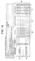
- FIG. 14 is a schematic illustration of the contents of the control table 40 that are updated in Step 302 when the second additional disk device 25 is added.
- FIG. 15 is a schematic illustration of the contents of the control table 40 that are updated in Step 316 after the completion of the copying operation.
- a processing operation described above for adding the second additional disk device 25 is carried out when adding a third additional disk device 26 and when adding a fourth additional disk device 27.
- the first through fourth redundancy groups formed on the added disk devices 24 through 27 and the fifth through eighth redundancy groups formed on the initial disk devices 20 through 23 are separated from each other for RAID configuration, it is possible to add a disk device 28 to the added disk devices 24 through 27 or the initial disk devices 20 through 23.
- the IO processing section 30 of the disk array controller 11 receives a read command (Step 400), it has the exclusivity control section 33 lock the control table 40 (Step 401) and has the read position browsing section 31 take out the disk numbers and the partition positions of the redundancy group specified by the read command from the ordinary configuration information 47 in the control table 40 (Step 402). Then, it unlocks the control table 40 (Step 403). Thereafter, the IO processing section 30 reads the relevant data of the disk array by way of the disk control section 37 according to the disk numbers and the partition positions taken out by using the read position browsing section 31 in Step 402. The addition-caused configuration information 48 is not used for the operation of processing the read command.
- the contents of the control table 40 are those shown in FIG. 10 so that the partition 100 of the disk device 20, the partition 101 of the disk device 21, the partition 102 of the disk device 22 and the partition 103 of the disk device 23 are accessed according to the read command specifying the first redundancy group.
- the operation of reading the data of the first partition is carried out on the partition 100 of the disk device 20.
- the control table 40 is updated as shown in FIG.
- the partition 104 of the disk device 24 the partition 101 of the disk device 21, the partition 102 of the disk device 22 and the partition 103 of the disk device 23 are accessed according to the read command specifying the first redundancy group.
- the operation of reading the data of the first partition is carried out not on the partition 100 of the disk device 20 but on the partition 104 of the disk device 24.
- the operation of the disk array controller 11 that takes place when a write command is issued from the host computer 10 will be described by referring to FIG. 17.
- the IO processing section 30 of the disk array controller 11 receives a write command (Step 500)
- the write position browsing section 32 takes out the disk numbers and the partition positions of the redundancy group specified by the write command from the ordinary configuration information 47 in the control table 40 (Step 502).
- Step 503 it confirms the state flag 41 (Step 503) and, if the flag indicates an adding state, it detects the difference between the ordinary configuration information 47 and the addition-caused configuration information 48 (Step 504) and adds the relevant data as data to be written also to the partition detected as difference (Step 505).
- the write command is for the first redundancy group in the control table 40 illustrated in FIG. 12, the partition 0 of the disk device 20 in the ordinary configuration information 47 is replaced by the partition 0 of the disk device 24 in the addition-caused configuration information 48 to make a difference so that the data to be written to the partition 0 of the disk device 20 is added to the relevant data so as to be written to the partition 0 of the disk device 24.
- the IO processing section 30 unlocks the control table 40 (Step 506) and carries out the operation of writing data to the partitions of the disk devices with the disk numbers taken out in Step 502 and Step 505 according to the write command (Step 507).
- the present invention is applied to a disk array of RAID 5 (3D + P) for the above described embodiment and example, the present invention is also applicable to a disk array of any RAID5 type other than RAID5 (3D + P) type and also to a disk array of any RAID type other than RAID5 type such as RAID1, RAID2, RAID3, RAID4 or RAID6 type.
- each disk device is equally divided by five when the present invention is applied to a disk array of RAID5 (4D + P) and the storage region of each disk device is equally divided by six when the present invention is applied to a disk array of RAID5 (5D + P), whereas the storage region of each disk device is equally divided by two when the present invention is applied to a disk array of RAID1 and the storage region of each disk device is equally divided also by six when the present invention is applied to a disk array of RAID6 (4D + P + Q).
- a method of adding a disk device according to the invention can be realized by equally dividing the storage region of each disk device by the smallest number of disk devices necessary for constituting a disk array of the RAID type.
- each disk device of a disk array of RAID5 3D + P
- tq equally divide the storage region by eight or by sixteen.
- M being a positive integer
- the disk devices 20 through 28 connected to the disk array controller 11 have a same storage capacity in the above description, they do not necessarily have to have a same storage capacity. If the initial disk devices that are used initially to generate a disk array have different storage capacities and the smallest capacity of them is X, the present invention can be applied by equally dividing the X storage capacity from the head of each of all the initial disk devices by the smallest number N of disk devices by a multiple thereof, or M ⁇ N. The above description also applies to the added disk devices.
- the expression of equally dividing the storage region of a disk device by N or by M ⁇ N for the purpose of the present invention does not always mean that all the storage region of the disk device is equally divided by N or by M ⁇ N but may mean that the storage region of X storage capacity from the head of the disk device is equally divided by N or by M ⁇ N.
- the first redundancy group may be defined by combining the four partitions of a same level including the uppermost partition 100 of the disk device 20, the uppermost partition 110 of the disk device 21, the uppermost partition 120 of the disk device 22 and the uppermost partition 130 of the disk device 23.
- the second redundancy group may be defined by combining the four partitions of another same level including the partitions 131, 101, 111 and 121 and the third redundancy group may be defined by combining the four partitions of still another same level including the partitions 122, 132, 102 and 112, while the fourth redundancy group may be defined by combining the four partitions of still another level including the partitions 113, 123, 133 and 103. Then, when the disk device 24 is added as shown in FIG.
- the partitions 100, 101, 102 and 103 are excluded form the redundancy groups to redefine the first redundancy group of the partitions 104, 110, 120 and 130, the second redundancy group of the partitions 131, 114, 111 and 121, the third redundancy group of the partitions 122, 132, 124 and 112, and the fourth redundancy group of the partitions 113, 123, 133 and 134.
- the partitions 100, 101, 102 and 103 that are excluded from the redundancy groups are redefined for the fifth redundancy group.
- a disk array device and a method of extending the storage capacity of a disk array device according to the invention are useful as a device and a method adapted to extend the storage capacity of a disk array constituted by a plurality of disk devices. They are particularly suited as a device and a method for extending the storage capacity of a disk device of RAID5 type or the like without suspending the operation of the system of the disk array device.
Landscapes
- Engineering & Computer Science (AREA)
- Theoretical Computer Science (AREA)
- Quality & Reliability (AREA)
- Physics & Mathematics (AREA)
- General Engineering & Computer Science (AREA)
- General Physics & Mathematics (AREA)
- Information Retrieval, Db Structures And Fs Structures Therefor (AREA)
- Techniques For Improving Reliability Of Storages (AREA)
Applications Claiming Priority (2)
| Application Number | Priority Date | Filing Date | Title |
|---|---|---|---|
| JP2003331329A JP4215606B2 (ja) | 2003-09-24 | 2003-09-24 | ディスクアレイ装置および記憶容量拡張方法ならびにプログラム |
| JP2003331329 | 2003-09-24 |
Publications (2)
| Publication Number | Publication Date |
|---|---|
| EP1519271A2 true EP1519271A2 (de) | 2005-03-30 |
| EP1519271A3 EP1519271A3 (de) | 2010-06-02 |
Family
ID=34191444
Family Applications (1)
| Application Number | Title | Priority Date | Filing Date |
|---|---|---|---|
| EP04104614A Withdrawn EP1519271A3 (de) | 2003-09-24 | 2004-09-23 | Speicherplattenanordnung, Verfahren zur Erweiterung der Speicherkapazität und Computerprogramm |
Country Status (3)
| Country | Link |
|---|---|
| US (1) | US7194580B2 (de) |
| EP (1) | EP1519271A3 (de) |
| JP (1) | JP4215606B2 (de) |
Cited By (1)
| Publication number | Priority date | Publication date | Assignee | Title |
|---|---|---|---|---|
| EP2282260A2 (de) * | 2009-07-30 | 2011-02-09 | LSI Corporation | Erasure-Coding-Datenspeicherkapazität und Energieverwaltung |
Families Citing this family (36)
| Publication number | Priority date | Publication date | Assignee | Title |
|---|---|---|---|---|
| JP4406402B2 (ja) * | 2003-07-02 | 2010-01-27 | 聰 山竹 | データベースシステム |
| JP2006318017A (ja) * | 2005-05-10 | 2006-11-24 | Nec System Technologies Ltd | Raid構成変換方法、装置及びプログラム並びにこれを用いたディスクアレイ装置 |
| US7694072B2 (en) * | 2005-09-22 | 2010-04-06 | Xyratex Technology Limited | System and method for flexible physical-logical mapping raid arrays |
| US7404036B2 (en) * | 2005-11-23 | 2008-07-22 | International Business Machines Corporation | Rebalancing of striped disk data |
| EP2158542B1 (de) * | 2006-04-04 | 2019-06-05 | Red Hat, Inc. | Kodierverfahren zur speicherzuweisung und löschung für skalierbares und fehlertolerantes speichersystem |
| US7500072B2 (en) * | 2006-04-25 | 2009-03-03 | International Business Machines Corporation | Migrating data that is subject to access by input/output devices |
| JP2009199426A (ja) * | 2008-02-22 | 2009-09-03 | Nec Corp | 論理ディスク再構築装置、ディスクアレイ装置、及び論理ディスク再構築方法 |
| US8161310B2 (en) * | 2008-04-08 | 2012-04-17 | International Business Machines Corporation | Extending and scavenging super-capacitor capacity |
| US8219740B2 (en) * | 2008-06-25 | 2012-07-10 | International Business Machines Corporation | Flash sector seeding to reduce program times |
| US8040750B2 (en) * | 2008-06-25 | 2011-10-18 | International Business Machines Corporation | Dual mode memory system for reducing power requirements during memory backup transition |
| US8037380B2 (en) * | 2008-07-08 | 2011-10-11 | International Business Machines Corporation | Verifying data integrity of a non-volatile memory system during data caching process |
| US8093868B2 (en) * | 2008-09-04 | 2012-01-10 | International Business Machines Corporation | In situ verification of capacitive power support |
| US8799571B1 (en) * | 2008-09-26 | 2014-08-05 | Emc Corporation | System and method for configuring a device array upon detecting addition of a storage device |
| US20100287329A1 (en) * | 2009-05-06 | 2010-11-11 | Apple Inc. | Partial Page Operations for Non-Volatile Memory Systems |
| JP2011003032A (ja) * | 2009-06-18 | 2011-01-06 | Toshiba Corp | 映像蓄積再生装置 |
| KR101562794B1 (ko) | 2009-08-04 | 2015-10-26 | 삼성전자주식회사 | 데이터 저장 장치 |
| US8510493B2 (en) * | 2010-12-27 | 2013-08-13 | Lsi Corporation | Circuit to efficiently handle data movement within a cache controller or on-chip memory peripheral |
| US9037679B2 (en) | 2012-12-31 | 2015-05-19 | Futurewei Technologies, Inc. | Efficient high availability storage systems |
| CN103927122B (zh) * | 2013-01-11 | 2017-02-08 | 中兴通讯股份有限公司 | 一种扩展磁盘阵列的方法及装置 |
| JP5907100B2 (ja) * | 2013-03-21 | 2016-04-20 | 日本電気株式会社 | ディスク制御装置およびディスクの減設方法、ストレージシステム、並びにコンピュータ・プログラム |
| JP6307962B2 (ja) * | 2014-03-19 | 2018-04-11 | 日本電気株式会社 | 情報処理システム、情報処理方法、及び、情報処理プログラム |
| US10198461B2 (en) * | 2016-05-06 | 2019-02-05 | Masergy Communications, Inc. | Data storage system |
| JP2018185757A (ja) * | 2017-04-27 | 2018-11-22 | 富士通株式会社 | ストレージ制御装置、ストレージ制御方法、およびストレージ制御プログラム |
| JP6767319B2 (ja) * | 2017-07-31 | 2020-10-14 | 株式会社ソニー・インタラクティブエンタテインメント | 情報処理装置およびファイルコピー方法 |
| US11079957B2 (en) * | 2019-11-01 | 2021-08-03 | Dell Products L.P. | Storage system capacity expansion using mixed-capacity storage devices |
| JP7261756B2 (ja) * | 2020-02-10 | 2023-04-20 | 株式会社日立製作所 | ストレージシステム、処理方法 |
| US11403022B2 (en) * | 2020-06-03 | 2022-08-02 | Dell Products L.P. | Growing and splitting a disk array by moving RAID group members |
| US11314608B1 (en) * | 2020-10-02 | 2022-04-26 | Dell Products L.P. | Creating and distributing spare capacity of a disk array |
| US11340789B2 (en) * | 2020-10-13 | 2022-05-24 | Dell Products L.P. | Predictive redistribution of capacity in a flexible RAID system |
| US11893259B2 (en) | 2021-01-07 | 2024-02-06 | EMC IP Holding Company LLC | Storage system configured with stealth drive group |
| US11748016B2 (en) * | 2021-05-06 | 2023-09-05 | EMC IP Holding Company LLC | Method for adding disks in a raid system having a protection pool of storage units |
| US11733922B2 (en) | 2021-05-06 | 2023-08-22 | EMC IP Holding Company LLC | Method for data reconstruction in a RAID system having a protection pool of storage units |
| US11989449B2 (en) | 2021-05-06 | 2024-05-21 | EMC IP Holding Company LLC | Method for full data reconstruction in a raid system having a protection pool of storage units |
| US11640343B2 (en) | 2021-05-06 | 2023-05-02 | EMC IP Holding Company LLC | Method for migrating data in a raid system having a protection pool of storage units |
| US12008271B1 (en) * | 2023-04-19 | 2024-06-11 | Dell Products L.P. | Adaptive raid width and distribution for flexible storage |
| CN119292525B (zh) * | 2024-09-25 | 2025-11-25 | 山东云海国创云计算装备产业创新中心有限公司 | 磁盘阵列扩容状态下的数据保护方法、终端及存储介质 |
Citations (1)
| Publication number | Priority date | Publication date | Assignee | Title |
|---|---|---|---|---|
| WO2003077111A1 (en) | 2002-03-13 | 2003-09-18 | Fujitsu Limited | Controller for raid device |
Family Cites Families (13)
| Publication number | Priority date | Publication date | Assignee | Title |
|---|---|---|---|---|
| US5502836A (en) * | 1991-11-21 | 1996-03-26 | Ast Research, Inc. | Method for disk restriping during system operation |
| JP3249868B2 (ja) | 1993-11-19 | 2002-01-21 | 株式会社日立製作所 | アレイ形式の記憶装置システム |
| US5615352A (en) | 1994-10-05 | 1997-03-25 | Hewlett-Packard Company | Methods for adding storage disks to a hierarchic disk array while maintaining data availability |
| US5524204A (en) * | 1994-11-03 | 1996-06-04 | International Business Machines Corporation | Method and apparatus for dynamically expanding a redundant array of disk drives |
| JP3008801B2 (ja) | 1995-02-16 | 2000-02-14 | 株式会社日立製作所 | 記憶装置システムおよびディスクアレイ制御装置 |
| US5875456A (en) * | 1995-08-17 | 1999-02-23 | Nstor Corporation | Storage device array and methods for striping and unstriping data and for adding and removing disks online to/from a raid storage array |
| JP3170455B2 (ja) * | 1996-05-27 | 2001-05-28 | インターナショナル・ビジネス・マシーンズ・コーポレ−ション | データ記憶システムにおけるデータの再配置方法、そのシステムに記憶されたデータのアクセス方法及びデータ記憶システム |
| US6000010A (en) * | 1997-05-09 | 1999-12-07 | Unisys Corporation | Method of increasing the storage capacity of a level five RAID disk array by adding, in a single step, a new parity block and N--1 new data blocks which respectively reside in a new columns, where N is at least two |
| JP2000010738A (ja) | 1998-06-17 | 2000-01-14 | Toshiba Corp | ディスクアレイシステム、同システムに適用される記憶容量拡張方法および記録媒体 |
| US7111117B2 (en) * | 2001-12-19 | 2006-09-19 | Broadcom Corporation | Expansion of RAID subsystems using spare space with immediate access to new space |
| JP3702231B2 (ja) * | 2002-01-31 | 2005-10-05 | 株式会社東芝 | ディスクアレイ装置及び同装置における動的記憶容量拡張方法 |
| US6898668B2 (en) * | 2002-06-24 | 2005-05-24 | Hewlett-Packard Development Company, L.P. | System and method for reorganizing data in a raid storage system |
| JP2004213064A (ja) * | 2002-12-26 | 2004-07-29 | Fujitsu Ltd | Raid装置及びその論理デバイス拡張方法 |
-
2003
- 2003-09-24 JP JP2003331329A patent/JP4215606B2/ja not_active Expired - Lifetime
-
2004
- 2004-09-23 US US10/947,266 patent/US7194580B2/en not_active Expired - Lifetime
- 2004-09-23 EP EP04104614A patent/EP1519271A3/de not_active Withdrawn
Patent Citations (1)
| Publication number | Priority date | Publication date | Assignee | Title |
|---|---|---|---|---|
| WO2003077111A1 (en) | 2002-03-13 | 2003-09-18 | Fujitsu Limited | Controller for raid device |
Cited By (1)
| Publication number | Priority date | Publication date | Assignee | Title |
|---|---|---|---|---|
| EP2282260A2 (de) * | 2009-07-30 | 2011-02-09 | LSI Corporation | Erasure-Coding-Datenspeicherkapazität und Energieverwaltung |
Also Published As
| Publication number | Publication date |
|---|---|
| JP4215606B2 (ja) | 2009-01-28 |
| EP1519271A3 (de) | 2010-06-02 |
| US7194580B2 (en) | 2007-03-20 |
| US20050063217A1 (en) | 2005-03-24 |
| JP2005099998A (ja) | 2005-04-14 |
Similar Documents
| Publication | Publication Date | Title |
|---|---|---|
| US7194580B2 (en) | Disk array device, method of extending storage capacity and computer program | |
| US20220236891A1 (en) | Storage system and data management method | |
| US7213166B2 (en) | In-place data transformation for fault-tolerant disk storage systems | |
| US10977124B2 (en) | Distributed storage system, data storage method, and software program | |
| JP3792269B2 (ja) | 階層ディスク・アレイにおいて容量の異なる記憶ディスクを単一記憶ボリューム内で使用する方法 | |
| US7620843B2 (en) | Rebuilding a storage system | |
| US7136964B2 (en) | Disk array with spare logic drive created from spare physical drives | |
| US10353787B2 (en) | Data stripping, allocation and reconstruction | |
| CN100377064C (zh) | 存储系统 | |
| US7013364B2 (en) | Storage subsystem having plural storage systems and storage selector for selecting one of the storage systems to process an access request | |
| US20070143541A1 (en) | Methods and structure for improved migration of raid logical volumes | |
| KR20110093035A (ko) | 플래시 주소 변환 장치 및 그 방법 | |
| US7346733B2 (en) | Storage apparatus, system and method using a plurality of object-based storage devices | |
| US8656131B2 (en) | Method and apparatus for expanding a virtual storage device | |
| CN110209340B (zh) | 一种全闪存存储系统的访问方法及装置 | |
| JP2020144459A (ja) | ストレージシステム、データ管理方法、及びデータ管理プログラム | |
| JPH0863298A (ja) | ディスクアレイ装置 | |
| CN100470507C (zh) | 磁盘阵列结构中进行回写的方法 | |
| JP2003196032A (ja) | ストレージ装置のライトキャッシュ制御方法及びストレージ装置 | |
| US7290087B2 (en) | Adaptive grouping in object raid | |
| JPH07200187A (ja) | ディスクアレイ装置 | |
| JP2005190047A (ja) | データソート機能を持つストレージシステム | |
| US6862661B2 (en) | Object oriented approach to a redundant array storage system | |
| JPH0863394A (ja) | 記憶装置システムおよび記憶装置の制御方法 | |
| JPH07160434A (ja) | アレイ形式の記憶装置システム |
Legal Events
| Date | Code | Title | Description |
|---|---|---|---|
| PUAI | Public reference made under article 153(3) epc to a published international application that has entered the european phase |
Free format text: ORIGINAL CODE: 0009012 |
|
| AK | Designated contracting states |
Kind code of ref document: A2 Designated state(s): AT BE BG CH CY CZ DE DK EE ES FI FR GB GR HU IE IT LI LU MC NL PL PT RO SE SI SK TR |
|
| AX | Request for extension of the european patent |
Extension state: AL HR LT LV MK |
|
| PUAL | Search report despatched |
Free format text: ORIGINAL CODE: 0009013 |
|
| AK | Designated contracting states |
Kind code of ref document: A3 Designated state(s): AT BE BG CH CY CZ DE DK EE ES FI FR GB GR HU IE IT LI LU MC NL PL PT RO SE SI SK TR |
|
| AX | Request for extension of the european patent |
Extension state: AL HR LT LV MK |
|
| 17P | Request for examination filed |
Effective date: 20101109 |
|
| 17Q | First examination report despatched |
Effective date: 20101216 |
|
| AKX | Designation fees paid |
Designated state(s): FR |
|
| REG | Reference to a national code |
Ref country code: DE Ref legal event code: 8566 |
|
| STAA | Information on the status of an ep patent application or granted ep patent |
Free format text: STATUS: THE APPLICATION HAS BEEN WITHDRAWN |
|
| 18W | Application withdrawn |
Effective date: 20170926 |