EP1519269A2 - Verfahren und System zum Echtzeit-Scheduling - Google Patents
Verfahren und System zum Echtzeit-Scheduling Download PDFInfo
- Publication number
- EP1519269A2 EP1519269A2 EP04021572A EP04021572A EP1519269A2 EP 1519269 A2 EP1519269 A2 EP 1519269A2 EP 04021572 A EP04021572 A EP 04021572A EP 04021572 A EP04021572 A EP 04021572A EP 1519269 A2 EP1519269 A2 EP 1519269A2
- Authority
- EP
- European Patent Office
- Prior art keywords
- tasks
- thread
- data transfer
- vpu
- real
- Prior art date
- Legal status (The legal status is an assumption and is not a legal conclusion. Google has not performed a legal analysis and makes no representation as to the accuracy of the status listed.)
- Withdrawn
Links
Images


Classifications
-
- G—PHYSICS
- G06—COMPUTING OR CALCULATING; COUNTING
- G06F—ELECTRIC DIGITAL DATA PROCESSING
- G06F9/00—Arrangements for program control, e.g. control units
- G06F9/06—Arrangements for program control, e.g. control units using stored programs, i.e. using an internal store of processing equipment to receive or retain programs
- G06F9/46—Multiprogramming arrangements
- G06F9/48—Program initiating; Program switching, e.g. by interrupt
- G06F9/4806—Task transfer initiation or dispatching
- G06F9/4843—Task transfer initiation or dispatching by program, e.g. task dispatcher, supervisor, operating system
- G06F9/4881—Scheduling strategies for dispatcher, e.g. round robin, multi-level priority queues
Definitions
- the present invention relates to a scheduling method and an information processing system for performing a real-time operation periodically at specific time intervals.
- system architecture such as a multiprocessor and a parallel processor in order to improve in throughput. Both of the processors achieve a parallel computing operation using a plurality of processing units.
- Jpn. Pat. Appln. KOKAI Publication No. 10-143380 discloses a system having a plurality of processing units. This system includes a single high-speed CPU, a plurality of low-speed CPUs and a shared memory. Processes are assigned to the high-speed and low-speed CPUs in consideration of parallelism and execution time of each process.
- Jpn. Pat. Appln. KOKAI Publication No. 8-180025 discloses a scheduling technique of scheduling threads such that the same processor executes threads belonging to the same process.
- each operation needs completing within the limit of allowed time.
- all the chained tasks need completing within the time interval of each period.
- An object of the present invention is to provide a method and an information processing system capable of decreasing a required data transfer bandwidth without impairing any real-time operation.
- a method of performing a plurality of tasks within a specific time interval using a plurality of processors which transfers data via a bus comprising inputting cost information concerning a time required to perform each of the tasks and bandwidth information concerning a data transfer bandwidth required by each of the tasks, and performing a scheduling operation of determining execution start timing of each of the tasks and at least one of the processors which executes the tasks, based on the input cost information and bandwidth information, to perform the tasks within the specific time interval without overlapping execution terms of at least two tasks of the tasks, the two tasks requiring data transfer bandwidths not less than those of the others of the tasks.
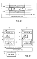
- FIG. 1 shows an example of a configuration of a computer system for achieving a real-time processing system according to an embodiment of the present invention.
- the computer system is an information processing system that performs various operations, which need to be done in real time, under timing constraint.
- the computer system can be used as not only a general-purpose computer but also an embedded system for various electronic devices to perform operations that need to be done in real time.
- the computer system comprises an MPU (master processing unit) 11, a plurality of VPUs (versatile processing units) 12, a connecting device 13, a main memory 14 and an I/O (input/output) controller 15.
- the MPU 11, VPUs 12, main memory 14 and IO controller 15 are connected to each other by the connecting device 13.
- the connecting device 13 is a data transfer path including a bus.
- a bus For example, a ring-shaped bus structure or an inter-connection network such as a crossbar switch can be used for the bus. If a bus is used for the connecting device 13, it can be shaped like a ring.
- the MPU 11 is a main processor that controls an operation of the computer system.
- the MPU 11 mainly executes an OS (operating system).
- the VPUs 12 and IO controller 15 can execute some functions of the OS.
- Each of the VPUs 12 is a processor for performing various operations under the control of the MPU 11.
- the MPU 11 distributes the operations (tasks) to the VPUs 12 in order to perform these operations (tasks) in parallel. The operations can thus be performed at high speed and with high efficiency.
- the main memory 14 is a storage device (shared memory) that is shared by the MPU 11, VPUs 12 and I/O controller 15.
- the main memory 14 stores the OS and application programs.
- the I/O controller 15 is connected to one or more I/O devices 16.
- the controller 15 is also referred to as a bridge device.
- the connecting device 13 has a QoS (quality of service) function that guarantees a data transfer rate.
- the QoS function is fulfilled by transferring data through the connecting device 13 at a reserved bandwidth (transfer rate).
- the QoS function is used when write data is transmitted to the memory 14 from one VPU 12 at 5 Mbps or when it is done between one VPU 12 and another VPU 12 at 100 Mbps.
- Each of the VPUs 12 designates (reserves) a bandwidth (transfer rate) for the connecting device 13.
- the connecting device 13 assigns the designated bandwidth to the VPU 12 by priority. If a bandwidth is reserved for data transfer of a VPU 12, it is secured even though another VPU 12, MPU 11 or IO controller 15 transfers a large amount of data during the data transfer of the former VPU 12.
- the QoS function is particularly important to computers that perform real-time operations.
- the computer system shown in FIG. 1 comprises one MPU 11, four VPUs 12, one memory 14 and one IO controller 15.
- the number of VPUs 12 is not limited.
- the system need not comprise any MPU and, in this case, one VPU 12 performs the operation of the MPU 11. In other words, one VPU 12 serves as a virtual MPU 11.
- the computer system also comprises a power saving controller 17.
- This controller 17 fulfills the following functions to lower the power consumption of all or part of the system.
- the above power saving functions can be fulfilled under the control of software.
- the power saving functions 1 to 13 can be done alone or in combination.
- FIG. 2 shows an MPU 11 and VPUs 12.
- the MPU 11 includes a processing unit 21 and a memory management unit 22.
- the processing unit 21 accesses the memory 14 through the memory management unit 22.
- the memory management unit 22 performs a virtual memory management function and manages a cache memory in the memory management unit 22.
- Each of the VPUs 12 includes a processing unit 31, a local storage (local memory) 32 and a memory controller 33.
- the processing unit 31 can gain direct access to the local storage 32 in the same VPU 12.
- the memory controller 33 serves as a DMA (direct memory access) controller that transfers data between the local storage 32 and memory 14.
- the memory controller 33 utilizes the QoS function of the connecting device 13 and has a function of designating a bandwidth and that of inputting/outputting data at the designated bandwidth.
- the memory controller 33 also has the same virtual memory management function as that of the memory management unit 22 of the MPU 11.
- the processing unit 31 uses the local storage 32 as a main memory.
- the processing unit 31 does not gain direct access to the memory 14 but instructs the memory controller 33 to transfer the contents of the memory 14 to the local storage 32.
- the processing unit 31 accesses the local storage 32 to read/write data.
- the processing unit 31 instructs the memory controller 33 to write the contents of the local storage 32 to the memory 14.
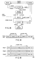
- the memory management unit 22 of the MPU 11 and the memory controllers 33 of the VPUs 12 perform virtual memory management as shown in FIG. 3.
- the address viewed from the processing unit 21 of the MPU 11 or the memory controllers 33 of the VPUs 12 is a 64-bit address as indicated in the upper part of FIG. 3.
- an upper 36-bit portion indicates a segment number
- a middle 16-bit portion indicates a page number
- a lower 12-bit portion indicates a page offset.
- the memory management unit 22 and memory controllers 33 each include a segment table 50 and a page table 60.
- the segment table 50 and page table 60 convert the 64-bit address into the real address space that is actually accessed through the connecting device 13.
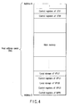
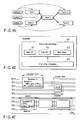
- the following data items are mapped in the real address (RA) space viewed from the MPU 11 and each VPU 12, as shown in FIG. 4.
- RA real address
- the MPU 11 and VPUs 12 can access any address in the real address space to read/write data items 1 to 5. It is particularly important to be able to access the real address space and thus access the local storage 32 of any VPU 12 from the MPU 11 and VPUs 12 and even from the I/O controller 15. Furthermore, the segment table 50 or page table 60 can prevent the contents of the local storage 32 of each VPU 12 from being read or written freely.
- FIG. 5 shows memory address spaces managed by the virtual memory management function shown in FIG. 3. It is the EA (effective address) space that is viewed directly from the programs executed on the MPU 11 or VPUs 12. An effective address is mapped in the VA (virtual address) space by the segment table 50. A virtual address is mapped in the RA (real address) space by the page table 60.
- the RA space has a structure as shown in FIG. 4.
- the MPU 11 can manage the VPUs 12 using a hardware mechanism such as a control register. For example, the MPU 11 can read/write data from/to the register of each VPU 12 and start/stop each VPU 12 to execute programs. Communication and synchronization between the MPU 11 and each of the VPUs 12 can be performed by means of a hardware mechanism such as a mailbox and an event flag, as can be communication and synchronization between the VPUs 12.
- a hardware mechanism such as a control register.
- the MPU 11 can read/write data from/to the register of each VPU 12 and start/stop each VPU 12 to execute programs.
- Communication and synchronization between the MPU 11 and each of the VPUs 12 can be performed by means of a hardware mechanism such as a mailbox and an event flag, as can be communication and synchronization between the VPUs 12.
- the computer system allows software to perform such an operation of an electric device that makes a stringent demand on real-time operations as conventionally implemented.
- one VPU 12 carries out a computation corresponding to some hardware components that compose the electric device and concurrently another VPU 12 carries out a computation corresponding to other hardware components that compose the electric device.
- FIG. 6 simply shows a hardware structure of a receiver for digital TV broadcast.
- a DEMUX (demultiplexer) circuit 101 divides a received broadcast signal into compressing-encoded data streams corresponding to audio data, video data and subtitle data.
- An A-DEC (audio decoder) circuit 102 decodes the compressing-encoded audio data stream.
- a V-DEC (video decoder) circuit 103 decodes the compressing-encoded video data stream.
- the decoded video data stream is sent to a PROG (progressive conversion) circuit 105 and converted into a progressive video signal.
- the progressive video signal is sent to a BLEND (image blending) circuit 106.
- a TEXT (subtitle data processing) circuit 104 converts the compressing-encoded subtitle data stream into a subtitle video signal and sends it to the BLEND circuit 106.
- the BLEND circuit 106 blends the video signal sent from the PROG circuit 105 and the subtitle video signal sent from the TEXT circuit 104 and outputs the blended signal as a video stream.
- a series of operations as described above is repeated at a video frame rate (e.g., 30, 32 or 60 frames per second).
- the present embodiment provides a program module 100 as shown in FIG. 7.
- the program module 100 is an application program for causing the computer system to perform the operations of the DEMUX circuit 101, A-DEC circuit 102, V-DEC circuit 103, TEXT circuit 104, PROG circuit 105 and BLEND circuit 106 shown in FIG. 6.
- the application program is described by multi-thread programming, and is structured as a group of threads for executing a real-time operation.
- the real-time operation includes a combination of a plurality of tasks.
- the program module 100 contains a plurality of programs (a plurality of routines) each executed as a thread.
- the program module 100 contains a DEMUX program 111, an A-DEC program 112, a V-DEC program 113, a TEXT program 114, a PROG program 115 and a BLEND program 116.
- These programs 111 to 116 are programs describing procedures of tasks corresponding to operations (DMUX operation, A-DEC operation, V-DEC operation, TEXT operation, PROG operation, BLEND operation) of the circuits 101 to 106. More specifically, when the program module 100 runs, a thread corresponding to each of the programs 111 to 116 is generated, and dispatched to one or more VPUs 12 and executed thereon.
- a program corresponding to the thread dispatched to the VPU 12 is loaded to the local storage 32 of the VPU 12, and the thread executes the program on the local storage 32.
- the program module 100 is obtained by packaging the programs 111 to 116, which correspond to hardware modules for configuring a receiver for digital TV broadcast, with data called a structural description 117.
- the structural description 117 is information indicative of how the programs (threads) in the program module 100 are combined and executed.
- the structural description 117 includes information indicative of a relationship in input/output (in chain) between chained programs 111 to 116 and costs (time) necessary for executing each of the programs 111 to 116.
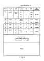
- FIG. 8 shows an example of the structural description 117.
- the structural description 117 shows modules (programs in the program module 100) each executed as a thread and their corresponding inputs, outputs, execution costs, and buffer sizes necessary for the outputs.
- the V-DEC program of No. (3) receives the output of the DEMUX program of No. (1) as an input and transmits its output to the PROG program of No. (5).
- the buffer necessary for the output of the V-DEC program is 1 MB and the cost for executing the V-DEC program in itself is 50.
- the cost can be described in units of time (time period) necessary for executing the program, or step number of the program. It also can be described in units of time required for executing the program by a virtual processor having some virtual specifications.
- the bus bandwidth in the structural description 117 is information indicating a data transfer bandwidth (data transfer speed) that is required for transferring data via the connecting device 13 by each of the programs 111 to 116.
- the data transfer is performed between VPUs, between a VPU and memory 14, or between a VPU and I/O device 16.
- the above QoS function allows a bandwidth required for performing an operation corresponding to each of the programs 111 to 116 to be secured. If the programs are executed according to the structural description 117 shown in FIG. 8, data flows among the programs as illustrated in FIG. 9.
- the structural description 117 also shows coupling attribute information which indicates a coupling attribute between threads corresponding to the programs 111 to 116 as thread parameters.
- the coupling attribute includes two different attributes of a tightly coupled attribute and a loosely coupled attribute.
- a plurality of threads having the tightly coupled attribute are executed in cooperation with each other and referred to as a tightly coupled thread group.
- the computer system of the present embodiment schedules the threads belonging to each tightly coupled thread group such that the threads belonging to the same tightly coupled thread group can simultaneously be executed by different VPUs.
- a plurality of threads having the loosely coupled attribute is referred to as a loosely coupled thread group.
- a programmer can designate a coupling attribute between threads corresponding to the programs 11 to 16 using thread parameters.
- the tightly and loosely coupled thread groups will be described in detail with reference to FIG. 25 et seq.
- the thread parameters including the coupling attribute information can be described directly as codes in the programs 111 to 116, not as the structural description 117.
- FIGS. 10 and 11 there now follows descriptions as to how the computer system of the present embodiment executes the programs 111 to 116.
- the computer system includes two VPUs of VPU0 and VPU1.
- FIG. 10 shows time for assigning the programs to each of the VPUs when video data of 30 frames is displayed per second. Audio and video data for one frame is output within a time interval corresponding to one period.
- the VPU0 executes the DEMUX program to perform the DEMUX operation and writes its resultant audio, video and subtitle data to the buffers.
- the VPU1 executes the A-DEC program and TEXT program to perform the A-DEC operation and the TEXT operation in sequence and writes their results to the buffers.
- the VPU0 executes the V-DEC program to perform the V-DEC operation and writes its result to the buffer.
- the VPU0 executes the PROG program to perform the PROG operation and writes its result to the buffer. Since the VPU1 has already completed the TEXT program at this time, the VPU0 executes the last BLEND program to perform the BLEND operation, in order to create final video data. The above processing is repeated for every period.
- scheduling An operation to determine which program is executed by each of the VPUs and when it is done to perform a desired operation without delay is called scheduling.
- a module to carry out the scheduling is called a scheduler.
- the scheduling is carried out based on the above structural description 117 contained in the program module 100.
- both execution start timing and execution term of each of threads that execute the programs 111 to 116 are determined based on the structural description 117, thereby to assign each of the threads to one or more VPUs 12. The following operations are performed when the program module 100 is to be executed.
- the execution start timing and execution term of each of threads (DEMUX, V-DEC, A-DEC, TEXT, PROG and BLEND) that executes the chained programs 111 to 116 in the program module 100 are determined based on the structural description 117.
- the threads for performing a real-time operation can efficiently be scheduled without describing timing constraint conditions of each operation in codes of a program.
- FIG. 11 shows the programs executed when video data of 60 frames is displayed per second.
- FIG. 11 differs from FIG. 10 as follows.
- data of 60 frames needs to be processed per second, whereas in FIG. 10, data of 30 frames is processed per second and thus data processing for one frame can be completed in one period (1/30 second).
- one-frame data processing cannot be completed in one period (1/60 second) and thus a software pipeline operation that spans a plurality of (two) periods is performed in FIG. 11.
- the VPU0 executes the DEMUX program and V-DEC program for the input signal.
- the VPU1 executes the A-DEC, TEXT, PROG and BLEND programs and outputs final video data.
- the VPU0 executes the DEMUX and V-DEC programs in the next frame.
- the DEMUX and V-DEC programs of the VPU0 and the A-DEC, TEXT, PROG and BLEND programs of the VPU1 are executed over two periods in pipeline mode.
- the two processors VPU1 and VPU2 can execute the second task group in parallel. For example, while the VPU1 executes the tasks A-DEC and TEXT, the VPU2 executes the tasks PROG and BLEND.
- a plurality of tasks DEMUX, V-DEC, A-DEC, TEXT, PROG and BLEND are executed by different threads.
- the above task groups can thus be referred to as thread groups.
- the program module 100 shown in FIG. 7 can be prerecorded in a flash ROM and a hard disk in a device incorporating the computer system of the present embodiment, or circulated through a network.
- the contents of operations to be performed by the computer system vary according to the type of a program module downloaded through the network.
- the device incorporating the computer system can perform the real-time operation corresponding to each of various pieces of dedicated hardware. If new player software, decoder software and encryption software necessary for reproducing new contents are distributed together with the contents as program modules executable by the computer system, any device incorporating the computer system can reproduce the contents within acceptable limits of ability.
- the computer system performs power saving control to decrease in power consumption, making sure that a real-time operation such as the above program module 100 is completed within a limited time period.
- a scheduling operation is carried out so as to complete a plurality of tasks of the real-time operation within a specific time interval and uniform required data transfer bandwidths within a period as much as possible.
- both one or more VPUs that execute the tasks and execution start timing of each of the tasks are determined to prevent the execution terms of at least two higher-order tasks having a large data transfer bandwidth from overlapping each other.
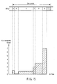
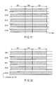
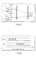
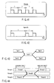
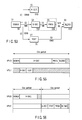
- FIG. 12 shows an example of scheduling to periodically perform a real-time operation including three tasks A, B and C on the VPU0 and VPU1. Assume that the total of costs (time) required for executing each of the tasks A, B and C is longer than the time interval corresponding to one period. Since one VPU cannot execute three tasks A, B and C within the time interval corresponding to one period, the tasks A, B and C are distributed to the VPU0 and VPU1. If the execution term of a task to be executed on the VPU0 and that of a task to be executed on the VPU1 overlap each other, the amount of data transfer (bandwidth required for the connecting device) increases within the overlapped term as shown in FIG. 12. In FIG.
- the bus bandwidths required by the tasks A, B and C are 100 Gbps, 90 Gbps and 20 Gbps, respectively. In the term where the execution terms of tasks A and B overlap, a bus bandwidth of 190 Gbps is required.
- the data transfer speed of the connecting device (bus) 13 needs to be set to satisfy the peak value of a required bus bandwidth in each period. The larger the peak value, the higher the data transfer speed of the connecting device (bus) 13 has to be. The connecting device (bus) 13 increases in power consumption accordingly.
- the scheduling operation according to the present embodiment is carried out in consideration of the bus bandwidth of each of the tasks A, B and C provided by the structural description 117 to minimize the peak value.
- the operating system performs the scheduling of the tasks A, B and C such that the tasks A, B and C are executed within a time interval corresponding to one period and the execution terms of at least two higher-order tasks (A and B in this case) having a large bus bandwidth are not overlapped each other.
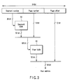
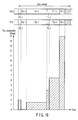
- FIG. 13 shows an example of scheduling to prevent the execution terms of tasks A and B from overlapping each other.
- the required data transfer bandwidth can be made almost uniform within a period and its peak can be lowered to a small value. Consequently, the data transfer speed of the connecting device (bus) 13 can be set low and thus the power consumption can be decreased, assuring that the real-time operation including the tasks A, B and C is periodically executed at specific time intervals.
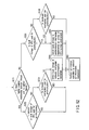
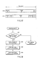
- Step S1 The operating system receives the structural description 117 from the external storage or memory 14 to check the execution order of tasks of the real-time operation, the costs required for executing each of the tasks, and the data transfer bandwidth required by each of the tasks.
- Step S2 Based on the above execution order, costs and data transfer bandwidth, the operating system performs a scheduling operation of determining one or more VPUs that execute the tasks and execution start timing of each of the tasks to satisfy three conditions for: (1) satisfying constraints of the execution order of the tasks; (2) executing all the tasks within a time interval corresponding to one period; and (3) preventing overlapping the execution terms of at least two higher-order tasks whose data transfer bandwidths are equal to or larger than those of the others of the tasks.
- Step S3 The operating system computes (determines) a peak value of data transfer bandwidth of data transfer to be performed by the determined one or more VPUs within the time interval, based on the results of scheduling in step S2 and the data transfer bandwidth required by each of the tasks.
- Step S4 The operating system computes a ratio of the computed peak value to the maximum data transfer bandwidth (maximum bus bandwidth) of the connecting device (bus) 13 based on the data transfer capability of the connecting device (bus) 13 and the computed peak value.
- Step S5 The operating system sets the data transfer speed of the connecting device (bus) 13 to a value that is lower than the maximum data transfer bandwidth based on the ratio computed in step S4.
- the data transfer speed of the connecting device (bus) 13 can be obtained by multiplying the maximum data transfer bandwidth of the device 13 by the computed ratio.
- the operating system transmits a command for designating the operating frequency of the device 13 or the bus bandwidth of the device 13 to the power saving controller 17.
- the power saving controller 17 includes a circuit for controlling the operating frequency of the device 13 or the bus bandwidth thereof.
- the power saving controller 17 sets the operating frequency or the bus bandwidth to one designated by the command from the operating system.
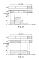
- FIG. 15 shows a bus bandwidth required when one VPU performs a digital TV broadcast receiving operation.
- the digital TV broadcast receiving operation contains a plurality of tasks (D: DEMUX, V: V-DEC, A: A-DEC, T: TEXT, P: PROG, B: BLEND).
- D DEMUX
- V V-DEC
- A A-DEC
- T TEXT
- P PROG
- B BLEND
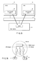
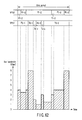
- FIG. 16 shows a bus bandwidth required when digital TV broadcast receiving operations for two channels are performed at the same time.
- the VPU0 performs a digital TV broadcast receiving operation for one channel and the VPU1 performs a digital TV broadcast receiving operation for the other channel. Since the tasks (BLEND) whose bus bandwidths are the largest overlap each other, the peak value of the bus bandwidth required in each period increases greatly.
- FIG. 17 shows an example of scheduling to perform digital TV broadcast receiving operations for two channels through the scheduling method according to the embodiment of the present invention.
- the execution term of the task (BLEND)) to be executed by the VPU1 is shifted using spare time in a period where no tasks are executed to thereby prevent tasks (BLEND) whose bus bandwidths are the largest from overlapping each other.
- the peak value of the bus bandwidth required in each period can thus be decreased to half the value in FIG. 16.
- the scheduling operation of the present embodiment which is performed in consideration of the bus bandwidth required by each task can be applied not only to scheduling for tasks contained in one real-time operation but also to scheduling for two or more real-time operations each of which needs to be performed within a specific time interval.
- Each real-time operation contains one or more tasks and there are no constraints of the execution order among the real-time operations. If each of two real-time operations contains only one task, scheduling can be performed to prevent the execution terms of the tasks from overlapping each other, based on only both the costs required for executing the tasks and the bus bandwidths of the tasks.
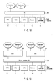
- OS operating system
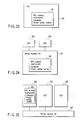
- 201 When only one OS (operating system) 201 is loaded into the computer system of the present embodiment, it manages all real resources (MPU 11, VPUs 12, memory 14, I/O controller 15, I/O device 16, etc.), as shown in FIG. 18.
- a virtual machine system can perform a plurality of OSes at once.
- a virtual machine OS 301 is loaded into the computer system to manage all real resources (MPU 11, VPUs 12, memory 14, I/O controller 15, I/O device 16, etc.).
- the virtual machine OS 301 is also referred to as a host OS.
- One or more OSes 302 and 303 that are also referred to as guest OSes are loaded on the virtual machine OS 301.
- the guest OSes 302 and 303 each run on a computer including virtual machine resources given by the virtual machine OS 301 and provide various services to application programs managed by the guest OSes 302 and 303.
- FIG. 20 the guest OSes 302 and 303 each run on a computer including virtual machine resources given by the virtual machine OS 301 and provide various services to application programs managed by the guest OSes 302 and 303.
- the guest OS 302 appears as if it operated on a computer including one MPU 11, two VPUs 12 and one memory 14, and the guest OS 303 appears as if it operated on a computer including one MPU 11, four VPUs 12 and one memory 14.
- the virtual machine OS 301 manages which one of VPUs 12 of the real resources actually corresponds to a VPU 12 viewed from the guest OS 302 and a VPU 12 viewed from the guest OS 303.
- the guest OSes 302 and 303 need not be aware of the correspondence.
- the virtual machine OS 301 schedules the guest OSes 302 and 303 to allocate all the resources in the computer system to the guest OSes 302 and 303 on a time-division basis. Assume that the guest OS 302 carries out a real-time operation. To perform the operation thirty times per second at an exact pace, the guest OS 302 sets its parameters to the virtual machine OS 301. The virtual machine OS 301 schedules the guest OS 302 to reliably assign necessary operation time to the guest OS 302 once per 1/30 second. The operation time is assigned to a guest OS that does not require a real-time operation by priority lower than a guest OS that requires a real-time operation. FIG.
- FIG. 21 shows that the guest OSes 302 and 303 run alternately, representing time by the horizontal axis. While the guest OS 302 (OS1) is running, the MPU 11 and all the VPUs 12 are used as resources of the guest OS 302 (OS1). While the guest OS 303 (OS2) is running, the MPU 11 and all the VPUs 12 are used as resources of the guest OS 303 (OS2).
- FIG. 22 shows a different operation mode.
- a VPU 12 be used continuously according to target applications. This case corresponds to, for example, an application that necessitates continuing to monitor data and events all the time.
- the scheduler of the virtual machine OS 301 manages the schedule of a specific guest OS such that the guest OS occupies a specific VPU 12.
- a VPU 3 is designated as a resource exclusively for a guest OS 302 (OS1). Even though the virtual machine OS 301 switches the guest OS 302 (OS1) and guest OS 303 (OS2) to each other, the VPU 3 always continues to operate under the control of the guest OS 302 (OS1).
- a software module called a VPU runtime environment is used.
- the soft module includes a scheduler for scheduling threads to be assigned to the VPUs 12.
- a VPU runtime environment 401 is implemented on the OS 201 as illustrated in FIG. 23.
- the VPU runtime environment 401 can be implemented in the kernel of the OS 201 or in a user program. It can also be divided into two for the kernel and user program to run in cooperation with each other.
- the following modes are provided to implement the VPU runtime environment 401:
- the scheduling of a guest OS managed by the virtual machine OS 301 and that of the VPUs can be combined into one.
- the scheduling can be done efficiently and finely and the resources can be used effectively;
- VPU runtime environment can be shared among a plurality of guest OSes, a new VPU runtime environment need not be created when a new guest OS is introduced.
- a scheduler for the VPUs can be shared among guest OSes on the virtual machine OS, the scheduling can be performed efficiently and finely and the resources can be used effectively;
- VPU runtime environment can be shared among a plurality of guest OSes, a new VPU runtime environment need not be created when a new guest OS is introduced;
- VPU runtime environment can be created without depending upon the virtual machine OS or a specific guest OS, it can be standardized easily and replaced with another. If a VPU runtime environment suitable for a specific embedded device is created to perform scheduling utilizing the characteristics of the device, the scheduling can be done with efficiency.
- VPU runtime environment can optimally be implemented in each guest OS, the scheduling can be performed efficiently and finely and the resources can be used effectively.
- VPU runtime environment need not be implemented in all the guest OSes, a new guest OS is easy to add.
- the VPU runtime environment 401 provides various services (a communication function using a network, a function of inputting/outputting files, calling a library function such as a codec, interfacing with a user, an input/output operation using an I/O device, reading of date and time, etc.) as well as functions of managing and scheduling various resources (operation time of each VPU, a memory, bandwidth of a connection device, etc.) associated with the VPUs 12.
- These services are called from application programs running on the VPUs 12. If a simple service is called, it is processed by service programs on the VPUs 12. A service that cannot be processed only by the VPUs 12, such as communication processing and file processing, is processed by service programs on the MPU 11.
- the programs that provide such services are referred to as a service provider (SP).
- SP service provider
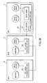
- FIG. 28 shows one example of the VPU runtime environment.
- the principal part of the VPU runtime environment is present on the MPU 11 and corresponds to an MPU-side VPU runtime environment 501.
- a VPU-side VPU runtime environment 502 is present on each of the VPUs 12 and has only the minimum function of carrying out a service that can be processed in the VPU 12.
- the function of the MPU-side VPU runtime environment 501 is roughly divided into a VPU controller 511 and a service broker 512.
- the VPU controller 511 chiefly provides a management mechanism, a synchronization mechanism, a security management mechanism and a scheduling mechanism for various resources (operation time of each VPU, a memory, a virtual space, bandwidth of a connection device, etc.) associated with the VPUs 12. It is the VPU controller 511 that dispatches programs to the VPUs 12 based on the results of scheduling. Upon receiving a service request called by the application program on each VPU 12, the service broker 512 calls an appropriate service program (service provider) and provides the service.
- service provider service provider
- the VPU-side VPU runtime environment 502 Upon receiving a service request called by the application program on each VPU 12, the VPU-side VPU runtime environment 502 processes only services that are processable in the VPU 12 and requests the service broker 512 to process services that are not processable therein.
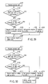
- FIG. 29 shows a procedure for processing a service request by the VPU-side VPU runtime environment 502.
- the VPU-side VPU runtime environment 502 determines whether the service can be processed therein (step S102). If the service can be processed, the VPU runtime environment 502 executes the service and returns its result to the calling part (steps S103 and S107). If not, the VPU runtime environment 502 determines whether a service program that can execute the service is registered as one executable on each VPU 12 (step S104). If the service program is registered, the VPU runtime environment 502 executes the service program and returns its result to the calling part (steps S105 and S107). If not, the VPU runtime environment 502 requests the service broker 512 to execute the service program and returns a result of the service from the service broker 512 to the calling part (steps S106 and S107) .
- FIG. 30 shows a procedure for processing a service that is requested by the VPU-side VPU runtime environment 502 by the service broker 512 of the MPU-side VPU runtime environment 501.
- the service broker 512 determines whether the VPU runtime environment 501 can process the service (step S112). If the service can be processed, the service broker 512 executes the service and returns its result to the VPU-side VPU runtime environment 502 of the calling part (steps S113 and S114). If not, the service broker 512 determines whether a service program that can execute the service is registered as one executable on the MPU 11 (step S114).
- the service broker 512 executes the service program and returns its result to the VPU-side VPU runtime environment 502 of the calling part (steps S116 and S114). If not, the service broker 512 returns an error to the VPU-side VPU runtime environment 502 of the calling part (step S117).
- the destination of the reply is usually a thread that issues a service request; however, another thread, a thread group or a process can be designated as the destination of the reply. It is thus favorable that the destination be included in a message to request a service.
- the service broker 512 can be realized using a widely used object request broker.
- the computer system serves as a real-time processing system.
- the operations to be performed by the real-time processing system are roughly divided into the following three types:
- the thread has the following three classes:
- the thread is a unit of execution for the real-time operation.
- the threads have their related programs that are to be executed by the threads.
- Each of the threads holds its inherent information that is called a thread context.
- the thread context contains, for example, information of a stack and values stored in the register of the processor.
- MPU 11 and VPU 12 processors that execute the threads and their models are identical with each other.
- the thread context of the VPU thread includes the contents of the local storage 32 of the VPU 12 and the conditions of a DMA controller of the memory controller 33.
- a group of threads is called a thread group.
- the thread group has the advantage of efficiently and easily performing, e.g., an operation of giving the same attribute to the threads of the group.
- the thread group in the hard or soft real-time class is roughly divided into a tightly coupled thread group and a loosely coupled thread group.
- the tightly coupled thread group and loosely coupled thread group are discriminated from each other by attribute information (coupling attribute information) added to the thread groups.
- the coupling attribute of the thread groups can explicitly be designated by the codes in the application programs or the above-described structural description.
- the tightly coupled thread group is a thread group that is made up of threads running in cooperation with each other.
- the threads belonging to the tightly coupled thread group tightly collaborate with each other.
- the tightly collaboration implies an interaction such as frequent communication and synchronization between threads or an interaction that decreases in latency.
- the threads belonging to the same tightly coupled thread group are always executed simultaneously.
- the loosely coupled thread group is a thread group that obviates a tightly collaboration between threads belonging to the group.
- the threads belonging to the loosely coupled thread group carry out communications for transferring data through the buffer on the memory 14.
- a tightly coupled thread group includes two tightly coupled threads A and B, and the threads A and B are executed at once by the VPU0 and VPU1, respectively.
- the real-time processing system of the present embodiment ensures that the threads A and B are executed at once by different VPUs.
- One of the threads can directly communicate with the other thread through a local storage or control register of the VPU that executes the other thread.
- FIG. 32 illustrates communication between threads A and B, which is performed through the local storages of VPU0 and VPU1 that execute the threads A and B, respectively.
- an RA space corresponding to the local storage 32 of the VPU1 that executes the thread B is mapped in part of an EA space of the thread A.
- an address translation unit 331 provided in the memory controller 33 of the VPU0 performs address translation using a segment table and page table.
- the address translation unit 331 converts (translates) a part of the EA space of the thread A to the RA space corresponding to the local storage 32 of the VPU1, thereby to map the RA space corresponding to the local storage 32 of the VPU1 in part of the EA space of the thread A.
- an RA space corresponding to the local storage 32 of the VPU0 that executes the thread A is mapped in part of an EA space of the thread B.
- an address translation unit 331 provided in the memory controller 33 of the VPU1 performs address translation using the segment table and page table.
- the address translation unit 331 converts a part of the EA space of the thread B to the RA space corresponding to the local storage 32 of the VPU0, thereby to map the RA space corresponding to the local storage 32 of the VPU0 in part of the EA space of the thread B.
- FIG. 33 shows mapping of local storage (LS1) 32 of the VPU1 executing the thread B in the EA space of the thread A executed by the VPU0 and mapping of local storage (LS0) 32 of the VPU0 executing the thread A in the EA space of the thread B executed by the VPU1.
- the thread A sets a flag indicative of this preparation in the local storage LS0 of the VPU0 or the local storage LS1 of the VPU1 that executes the thread B.
- the thread B reads the data from the local storage LS0.
- tightly coupled threads can be specified by the coupling attribute information, and the tightly coupled threads A and B are sure to be executed at once by different VPUs, respectively.
- an interaction of communication and synchronization between the threads A and B can be performed more lightly without delay.
- FIG. 34 shows a loosely coupled thread group including two threads C and D as loosely coupled threads, which are executed by their respective VPU0 and VPU1.
- the threads C and D differ in execution term as is apparent from FIG. 34. Communication between the threads C and D is carried out by the buffer prepared on the main memory 14 as shown in FIG. 35.
- the thread C executed by the VPU0 writes data, which is prepared in the local storage LS0, to the buffer prepared on the main memory 14 by DMA transfer.
- the thread D executed by the VPU1 reads data from the buffer on the main memory 14 and writes it to the local storage LS1 by DMA transfer when the thread D starts to run.
- a process includes one address space and one or more threads.
- the threads can be included in the process regardless of their number and type. For example, only VPU threads can be included in the process and so can be a mixture of VPU and MPU threads.
- the process context contains both an address space inherent in the process and thread contexts of all threads included in the process.
- the address space can be shared among all the threads of the process.
- One process can include a plurality of thread groups, but one thread group cannot belong to a plurality of processes. Thus, a thread group belonging to a process is inherent in the process.
- the existing thread (which is one for creating a new thread, i.e., a parent thread of the new thread) first designates a program to be executed by a new thread and causes the new thread to start to execute the program. The program is then stored in the local storage of the VPU and starts to run from a given address.
- the new thread can gain access to the local storage of the VPU and not to the memory 14.
- the new thread in itself calls a service of VPU runtime environment and creates an address space.
- the address space is related to the new thread, and the new thread can gain access to the memory 14.
- the existing thread creates a new address space or designates the existing address space, and arranges program, which is to execute by the new thread, in the address space. Then, the new thread starts to run the programs.
- the merit of the thread first model is that a thread can be executed only by the local storage to reduce overhead costs required for generating, dispatching and exiting the thread.
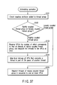
- the scheduler in the VPU runtime environment 401 checks a coupling attribute between threads based on coupling attribute information added to each group of threads to be scheduled (step S121).
- the scheduler determines whether each thread group is a tightly coupled thread group or a loosely coupled thread group (step S122).
- the coupling attribute is checked referring to the descriptions of threads in program codes or thread parameters in the above structural description 117. If the tightly and loosely coupled thread groups are each specified, the threads to be scheduled are separated into the tightly and loosely coupled thread groups.
- the scheduling of threads belonging to the tightly coupled thread group is performed as follows.
- the scheduler in the VPU runtime environment 401 reserves an execution term of each of the VPUs, whose number is equal to that of the threads, and dispatches the threads to the VPUs at once (step S123).
- the scheduler maps an RA space in part of an EA space of a thread using the address translation unit 331 in a VPU that executes the thread (step S124), the RA space corresponding to the local storage of a VPU that executes a partner thread interacting with the former thread.
- the scheduler dispatches the threads in sequence to one or more VPUs based on the relationship in input/output between the threads (step S125).
- a tightly coupled thread group which is a set of threads running in cooperation with each other, is selected based on the coupling attribute information, it can be ensured that the threads belonging to the tightly coupled thread group are executed at once by different processors. Consequently, communication between threads can be achieved by a lightweight mechanism of gaining direct access to, e.g., the registers of processors that execute their partner threads each other. The communication can thus be performed lightly and quickly.
- a thread generally makes a state transition from when it is created until it is deleted. As shown in FIG. 38, a thread makes the following seven state transitions.
- This transition is made by creating a thread.
- a thread context is created but its contents are in the initial state.
- This transition is made by deleting a thread.
- the stored thread context is discarded by the transition.
- This transition is made when the thread requests the runtime environment to schedule the thread.
- This transition is made when an event (e.g., synchronization, communication, timer interruption) for which the thread waits is generated.
- an event e.g., synchronization, communication, timer interruption
- This transition is made when the thread is dispatched to MPU or VPU by the runtime environment.
- the thread context is loaded. When the thread context is saved, it is restored.
- This transition is made when the thread suspends its own running to wait for an event using a synchronization mechanism, a communication mechanism and the like.
- the thread in every class can be set to store its thread context.
- the thread context is saved by the runtime environment when the thread transits from RUNNING state to WAITING state.
- the saved thread context is maintained unless the thread transits to DORMANT state and restored when the thread transits to the RUNNING state.
- This transition is made when the running of the thread is forcibly suspended in response to an instruction from the runtime environment or other threads.
- the thread in every class can be set to store its thread context.
- the thread context is saved by the runtime environment when the thread transits from RUNNING state to SUSPENDED state.
- the saved thread context is maintained unless the thread transits to DORMANT state and restored when the thread transits to the RUNNING state.
- This transition is made when the thread is forced to stop by instruction from outside while it is waiting for an event to generate in the WAITING state.
- This transition is made when the thread resumes running by instruction from outside while it is in the WAITING-SUSPENDED state.
- This transition is made when the event for which the thread waits in the WAITING state is generated.
- the term of the running state of a thread to which a VPU is allocated is called an execution term.
- a term from creation to deletion of a thread includes a plurality of execution terms of the thread.
- FIG. 39 shows an example of thread states varied from creation to deletion. This example includes two execution terms during the presence of the thread.
- the thread context can be saved and restored using various methods. Most normal threads run so as to save a context at the end of an execution term and restore the context at the beginning of the next execution term. In a certain periodic operation, the thread run so as to create a new context at the beginning of an execution term, use the context during the execution term, and discard the context at the end of the execution term in every period.
- FIG. 40 shows execution terms of threads belonging to the same tightly coupled thread group. All the threads belonging to a certain tightly coupled thread group are scheduled by the VPU runtime environment 401 such that they can run at once in one execution term. This tightly coupled thread group is used chiefly for hard real-time threads. In order to achieve the operation, therefore, the VPU runtime environment 401 designates processors used at once and their number when an execution term is reserved for the hard real-time class. Moreover, the VPU runtime environment 401 makes contexts of threads running at once correspondent to the processors, respectively.
- the threads which belonged to the tightly coupled thread group in a certain execution term, can run separately from each other in other execution term by canceling their tightly coupled relationship.
- Each of the threads has to sense whether it runs as a tightly coupled thread or separately from another thread and perform an operation of communication and synchronization with its partner thread.
- Each of the threads is provided with an attribute that indicates preemptive or non-preemptive.
- the preemptive attribute permits a thread to be preempted during its execution term and, in other words, permits the thread to stop running.
- the non-preemptive attribute ensures that a thread cannot be preempted during its execution term.
- the non-preemptive attribute varies in meaning from thread class to thread class.
- the hard real-time class when a thread starts to run, nothing but the thread in itself can stop the running until its execution term ends.
- the soft real-time class preemptiveness is essential and thus the non-preemptive attribute is not supported.
- a thread In the best effort class, a thread can be protected against being preempted from another best effort class, but it can be preempted from a higher-level class such as the hard real-time class and soft real-time class.
- the execution models of threads can roughly be classified into two models: a periodic execution model as shown in FIG. 41 and an aperiodic execution model as shown in FIG. 42.
- a periodic execution model a thread is executed periodically.
- a periodic running model a thread is executed based on an event.
- the periodic execution model can be implemented using a software interrupt or an event object such as synchronization primitives.
- the periodic execution model is implemented using a software interrupt.
- the VPU runtime environment 401 jumps to an entry point of a thread determined by a given method with timing to start a periodic operation or calls a callback function registered in advance by a given procedure.
- the periodic execution model is implemented using an event object.
- a soft real-time thread waits an event object in each period, and perform a given operation upon generation of the event, thereby realizing a periodic execution model.
- the periodic execution model can be implemented using either one of a software interrupt or an event object. The actual execution does not always start at the beginning of each period, but may be delayed within constraints.
- the aperiodic execution model can be realized as the periodic execution model.
- the aperiodic execution model differs from the periodic execution model only in the timing with which an event is notified and these models are the same in the implementing method.
- the minimum inter-arrival time and the dead line which are necessary for securing time requirements, strongly constrain the operation of the system; accordingly, the aperiodic execution is restricted.
- one of methods for switching a context at the end of the execution term of a VPU thread can be selected. Since the costs for switching the context are very high, the selection of one method improves the efficiency of switching. The selected method is used at the end of the reserved execution term of a thread.
- a context is switched during the execution term or at the time of preemption, all contexts of the current thread need to be saved in whatever case and restored when the thread resumes running next. For example, there are following methods of switching a VPU context.
- the context switching is delayed until all operations of the DMA controller in the memory controller in a VPU are completed. After that, the contents of the register and local storage in the VPU are saved. In this method, all the contexts of the VPU as well as the complete saving are saved.
- One scheduler can be implemented to schedule both MPU and VPU threads and different schedulers can be done to schedule their respective MPU and VPU threads. Since the MPU and VPU threads differ in costs for switching a context, the implementation of different schedulers becomes more efficient.
- FIG. 43 shows an example of the task graph.
- the task graph represents a relationship between tasks.
- the arrows between tasks indicate the dependence of the tasks (relationship in input/output between the tasks).
- tasks 1 and 2 can freely start to run
- a task 3 can start to run after both the tasks 1 and 2 stop running
- tasks 4 and 5 can start to run after the task 3 stops running.
- the task graph has no concepts of contexts. For example, when the tasks 1 and 4 should be processed using the same context, it cannot be described in the task graph.
- the following reservation graph of the extended task graph is therefore used in the real-time processing system of the present embodiment.
- the task graph By relating a context to each of the execution terms, a thread corresponding to the context runs in the execution term. If the same context is related to a plurality of execution terms, its corresponding thread runs in each of the execution terms.
- the context of thread 1 is related to execution terms 1 and 2, and the thread 1 runs in each of the execution terms 1 and 2.
- An attribute indicative of constraints of hard real-time ensured by the runtime environment is added to each of arrows between the execution terms.
- operation models and constraints such as time requirements of a real-time application can be described without making any modifications to the model of the real-time application.
- FIG. 45 shows an example of the reservation graph created based on the graph shown in FIG. 44. Contexts 1, 2 and 3 in FIG. 45 correspond to those of threads 1, 2 and 3 in FIG. 44, respectively.
- the scheduling of threads in the soft real-time class is performed using a fixed priority scheduling method in order to allow the running patterns of threads to be predicted.
- Two different scheduling algorithms are prepared for the scheduling method: one is fixed priority FIFO scheduling and the other is fixed priority round robin scheduling.
- the lower-priority thread is preempted and immediately the higher-priority thread starts to run.
- a synchronization mechanism such as a priority inheritance protocol and a priority ceiling protocol.
- the scheduling of threads in the best effort class is performed using dynamic priority scheduling and the like.
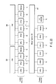
- the scheduling function in the VPU runtime environment 401 can be fulfilled as a hierarchical scheduler as shown in FIG. 46.
- thread-level scheduling has two hierarchies of thread inter-class scheduling and thread intra-class scheduling.
- the scheduler in the VPU runtime environment 401 has a thread intra-class scheduling section 601 and a thread inter-class scheduling section 602.
- the thread inter-class scheduling section 602 schedules threads spreading over thread classes.
- the thread intra-class scheduling section 601 schedules threads belonging to each of thread classes.
- the section 601 includes a hard real-time (hard RT) class scheduling section 611, a soft real-time (soft RT) class scheduling section 612 and a best effort class scheduling section 613.
- the thread inter-class scheduling and thread intra-class scheduling have a hierarchical structure.
- the thread inter-class scheduling operates to determine which thread class is executed and then which thread in the thread class is executed.
- the thread inter-class scheduling employs preemptive fixed priority scheduling.
- the hard real-time class has the highest priority, with the soft real-time class and the best effort class following in that order.
- a thread in a higher-priority class is ready to run, a lowest-priority thread is preempted.
- Synchronization between thread classes is achieved by a synchronous primitive provided by the VPU runtime environment 401. In particular, only the primitive can be used in a hard real-time thread to prevent a block from occurring in the hard real-time thread.
- a best effort thread blocks a soft real-time thread, it is processed as a soft real-time thread to prevent priority from being inverted between thread classes. Furthermore, the use of, e.g., the priority inheritance protocol prevents another soft real-time thread from blocking the best effort thread.
- threads are scheduled using various parameters.
- the parameters common to the threads in each class are as follows:
- FIG. 47 shows examples of fundamental parameters for the hard real-time class.
- example 1 to designate an execution term shown in the uppermost part of FIG. 47 one MPU and two VPUs are reserved at once in the designated execution term, and the context of each of the VPUs is completely saved.
- the threads run at the same time on the three processors and, after the execution term, the contexts of VPU threads as well as that of an MPU thread are completely saved.
- example 2 shows a method of designating a deadline to ensure that an operation represented by the number of VPUs and their execution term is performed before the deadline.
- the deadline is designated by relative time starting at the request time when a reservation request is made.
- example 3 shows a method of designating a periodic execution.
- an execution term that designates two VPUs 12 is periodically repeated, and the contexts of VPU threads are discarded after the execution term for each period, with the result that all operations are performed by new contexts.
- the deadline is designated by relative time starting at the beginning of the period.
- the timing constraints provide a unit which delays execution timing.
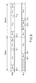
- the absolute timing constraint is a condition for designating delay time with reference to static timing, such as the start time of a period, as shown in FIG. 48.
- the relative timing constraint is a condition for designating permissible delay time with reference to dynamic timing and an event, such as the start time and end time of a certain, as shown in FIG. 49. Since the precedence constraint can be achieved by designating delay time as 0 or longer with reference to the end time of a certain execution term using the relative timing constraint, it can be considered to be a special one for the relative timing constraint.
- the mutual exclusive constraint is a condition for ensuring that execution terms do not overlap each other, as shown in FIG. 50.
- the mutual exclusive constraint makes it possible to lessen the prediction impossibility of the execution term, which is caused by a lock. In other words, all threads common to some resources are prevented from running at once to obviate a lock regarding the resources.
- the other synchronous primitives can be used.
- the real-time processing system of the present embodiment provides the following three methods to achieve the above synchronization mechanisms:
- a synchronization mechanism implemented using the memory (main storage MS) 14 that is shared and accessed by the MPU and VPUs can be used for threads in all classes.
- a synchronization mechanism implemented on the local storage LS of a VPU 12 can be used only for threads belonging to the tightly coupled thread group. This is because only the threads belonging to the tightly coupled thread group ensure that their partner threads for synchronization run at the same.
- the execution of the partner thread is ensured when the synchronization mechanism is used.
- the local storage of the VPU that executes the partner thread always stores information for the synchronization mechanism.
- a synchronization mechanism using a unit other than the memory (main storage MS) and local storage LS can be implemented by a hardware mechanism or a service of the VPU runtime environment 401. Since the threads belonging to the tightly coupled thread or those in the hard real-time class require a high-speed synchronization mechanism, the synchronization mechanism implemented by the hardware mechanism is desirable to use in the threads. In contrast, the synchronization mechanism provided by the runtime environment is desirable to use in the threads belonging to the loosely coupled thread group or those belonging to the soft real-time class and best effort class.
- the above synchronization mechanisms can automatically be selected or switched in accordance with the attribute and status of threads. This operation is performed by a procedure as shown in FIG. 52. While threads for synchronization belong to the tightly coupled thread group (YES in step S201), a high-speed synchronization mechanism that is implemented by the memory 14, the local storage 32 of each VPU 12 or the hardware mechanism is used (steps S202, S203, S204, S205).
- the high-speed synchronization mechanism is switched to a synchronization mechanism that is implemented as a synchronization mechanism on the memory 14 or a service of the VPU runtime environment 401 (steps S206, S207, S208).
- the above switching can be provided for programs running on the VPUs 12 in the form of a library or as a service of the VPU runtime environment 502 in each of the VPUs 12.
- a plurality of synchronization mechanisms can be switched as follows.
- the synchronization mechanisms can be secured in advance and used selectively or new synchronization mechanisms can be secured when the switching is performed.
- FIG. 53 shows a reservation graph corresponding to the data flow shown in FIG. 9.
- six boxes represent execution terms.
- the upper left number on each of the boxes indicates the ID of an execution term to be reserved.
- the symbol in each box indicates the identifier of a thread context related to the execution term.
- the lower right number on each box indicates the length (cost) of the execution term.
- the arrows connecting the boxes all denote precedence constraints. In other words, an arrow extending from one box to another box indicates that an operation in the execution term of the latter box starts after an operation in that of the former box is completed. A chain of execution terms can thus be represented.
- the number with each arrow denotes an ID of a buffer used for data transfer between execution terms connected by the arrow, and the value with each number denotes the size of a buffer.
- the following are procedures 1 to 7 for performing operations in accordance with the reservation graph shown in FIG. 53.
- the VPU runtime environment 401 assigns necessary resources to the program to create a thread context.
- the handle of the thread context is returned and thus referred to as an identifier.
- FIG. 54 shows a reservation request containing buffer data written as BUFFER and execution term data written as TASK.
- the buffer data is used to declare a buffer on the memory 14 for data transfer between execution terms.
- Id indicates buffer number
- Size indicates buffer size
- SrcTask shows execution term number that writes data
- DstTask shows execution term number that reads data.
- execution term data “Id” represents execution term number
- Class indicates thread class (VPU shows VPU thread and HRT shows hard real-time class.
- MPU showing MPU thread
- SRT showing soft real-time class
- BST showing best effort class and so on
- ThreadContext denotes thread context corresponding to the execution term
- Cost indicates length or cost of the execution term
- Constraint represents various constraints based on the execution term
- InputBuffer shows a list of identifiers of buffers read in the execution term
- OutputBuffer indicates a list of identifiers of buffers written in the execution term
- Band represents a required bus bandwidth.
- the “Constraint” also can include “Precedence” showing precedence constraint, “Absolute Timing” showing absolute timing constraint, “Relative Timing” showing relative timing constraint and “Exclusive” showing mutual exclusive constraint.
- the “Constraint” has a list of numbers of execution terms of partner threads for constraints.
- the buffer area reserved by the reservation request shown in FIG. 54 is allocated to the main memory 14 and released therefrom by the VPU runtime environment 401.
- the allocation of the buffer area is performed when a thread that writes data to the buffer area starts to run.
- the release of the buffer area is performed when a thread that reads data from the buffer area exits.
- the thread can be notified of the address of the allocated buffer using an address, a variable or a register that is predetermined when the thread starts to run.
- the program module 100 shown in FIG. 7 when the program module 100 shown in FIG. 7 is provided, the structural description 117 shown in FIG. 8 is read out of the program module 100 and, based on the structural description 117, a thread context is created by the above procedures and a reservation request as shown in FIG.
- FIG. 54 is created and issued, thereby providing a function of executing the program module 100.
- This function allows the operation of dedicated hardware described by the program module 100 as shown in FIG. 7 to be performed by processing software by a plurality of processors.
- a program module having a structure as shown in FIG. 7 is created for each hardware to be implemented and then executed by an apparatus having a function conforming to the real-time processing system of the present embodiment, with the result that the apparatus can be operated as desired hardware.
- an operation of creating the reservation request shown in FIG. 54 is described in the application program, and the application program can create a reservation request by itself and transfer it to the VPU runtime environment 401.
- the VPU runtime environment 401 determines which VPU 12 executes each task with which timing in a period. This is scheduling. Actually, a plurality of reservation requests can be provided at once; therefore, operation timing is determined to prevent them from contradicting each other (prevent given constraints from not being satisfied). Assuming that only the reservation request shown in FIG. 54 is made when there are two VPUs 12 as shown in FIG. 55, the scheduling is performed such that the VPU 0 sequentially performs DEMUX, V-DEC, PROG and BLEND operations which cannot be done in parallel and after the DEMUX operation, the VPU1 performs the A-DEC and TEXT operations that can be done in parallel.
- VPU 0 performs the DEMUX and V-DEC operations in the first period and the VPU 1 performs the A-DEC, TEXT, PROG and BLEND operations in the second period.
- the VPU 0 performs DEMUX and V-DEC operations in the next frame in parallel with the A-DEC, TEXT, PROG and BLEND operations.
- the pipeline processing is performed in which the VPU 1 performs the A-DEC, TEXT, PROG and BLEND operations upon receipt of outputs from the DEMUX and V-DEC operations in the preceding period while the VPU 0 is performing the DEMUX and V-DEC operations.
- Adopting the pipeline operation allows a real-time operation to be completed in each period in a shorter time.
- FIG. 58 is a flowchart of procedures for scheduling to achieve a software pipeline operation.
- the VPU runtime environment 401 determines whether all of the threads DEMUX, V-DEC, PROG and BLEND, which need to be executed in sequence, can be done within one period (step S401).
- the length of one period is preset to the VPU runtime environment 401 as an execution condition of the program module 100. The length can be described explicitly in the structural description 117.
- the total execution term of the threads DEMUX, V-DEC, PROG and BLEND is predicted based on the costs of these threads. The predicted total execution term is compared with the length of one period.
- the VPU runtime environment 401 determines that the threads DEMUX, V-DEC, PROG and BLEND cannot be executed within one period (NO in step S401), it divides all the threads DEMUX, V-DEC, A-DEC, TEXT, PROG and BLEND for executing the program module 100 into two groups (referred to as first and second thread groups hereinafter) that can be executed in sequence, based on the order of execution of the threads DEMUX, V-DEC, A-DEC, TEXT, PROG and BLEND (step S402).
- the first thread group is a set of one or more threads executed before the second thread group
- the second thread group is a set of one or more threads executed after the first thread group.
- the threads DEMUX and V-DEC belong to the first thread group and the threads A-DEC, TEXT, PROG and BLEND belong to the second thread group to satisfy the precedence constraints between the threads and make the total execution term of each of the groups not longer than the time interval corresponding to one period.
- the VPU runtime environment 401 performs the scheduling operation to periodically assign the execution term of each of the threads belonging to the first thread group (DEMUX and V-DEC) to the VPU0 to execute the first thread group on the VPU0 periodically at time intervals of 1/60 second (step S403).
- step S403 periodic execution of each of the threads DEMUX and V-DEC is reserved for the VPU0.
- the VPU runtime environment 401 performs the scheduling operation to periodically assign each of the threads belonging to the second thread group (A-DEC, TEXT, PROG and BLEND) to the VPU1 to execute the second thread group on the VPU1 periodically at time intervals of 1/60 second with a one-period delay relative to the first thread group (step S404).
- step S404 period execution of each of the threads A-DEC, TEXT, PROG and BLEND is reserved for the VPU1.
- Two processors VPU0 and VPU1 execute the first thread group (DEMUX and V-DEC) and the second thread group (A-DEC, TEXT, PROG and BLEND) in pipeline mode. Consequently, the first thread group and the second thread group are executed in parallel while the second thread group is delayed one period relative to the first thread group, thus outputting frame data processing results for each period of 1/60 second.
- the VPU0 always executes the first thread group (DEMUX and V-DEC) and the VPU1 always executes the second thread group (A-DEC, TEXT, PROG and BLEND).
- scheduling can be carried out to periodically replace a processor to which the first thread group is assigned and a processor to which the second thread group is assigned.
- execution timing of each of the first and second thread groups and different processors for executing the first and second thread groups are determined in each period to execute the first and second thread groups in parallel on the processors while the second thread group is delayed by one period relative to the first thread group.
- the above-described pipeline operation allows the constraints of execution timing of each of tasks to be eased within the range to satisfy the constraints of the execution order of the tasks. Even though each period has no spare time, scheduling can be performed to prevent the execution terms of tasks whose bus bandwidths are large from overlapping each other, by using of the pipeline operation.
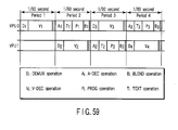
- FIG. 60 shows a bus bandwidth required when digital TV broadcast receiving operations for two channels are performed at the same time. If each period has no spare time, the execution term of BLEND to be executed by VPU0 and that of BLEND to be executed by VPU1 cannot simply be shifted from each other.
- FIG. 61 shows an example in which the above execution terms of BLEND are shifted by the pipeline operation.
- the real-time operation (D2: DEMUX, V2: V-DEC, A2: A-DEC, T2: TEXT, P2: PROG, B2: BLEND) to be performed by VPU1 is classified into a first thread group (V2, A2, T2, D2) and a second thread group (P2, B2).
- the second thread group (P2, B2) is executed with a one-period delay relative to the first thread group (V2, A2, T2, D2) and in period 2 the second thread group (P2, B2) is executed before the first thread group (V2, A2, T2, D2).
- FIG. 53 has no hierarchical structure
- a reservation graph having a hierarchical structure can be used as shown in FIG. 63.
- the execution term A precedes the execution term B and the execution term B precedes the execution term C.
- the execution term D precedes execution terms E and F. Resolving the hierarchy, the execution term A precedes the execution term D and the execution terms E and F precede the execution term C.
- FIG. 8 shows an example of the structural description 117 incorporated in the program module 100 shown in FIG. 7.
- the VPU runtime environment 401 performs the following steps.
- step 2 of creating the reservation request is performed as follows. First, BUFFER records are created to correspond to the output fields of the structural description 117 in a one-to-one basis and added to the reservation request. For instance, in the example of FIG. 8, the second output data of the DEMUX module is supplied to the V-DEC through the 1-MB buffer, so that a BUFFER record whose Id is 2 as shown in FIG. 54 is created.
- the buffer size is described as 1MB in Size field
- reference to TASK record whose Id is 1 and which corresponds to a DEMUX module that writes data to the buffer is described in SrcTask field
- reference to TASK record whose Id is 3 and which corresponds to a V-DEC module that reads data from the buffer is described in DstTask field.
- TASK records are created to correspond to the module fields of the structural description 117 on a one-to-one basis and added to the reservation request. For instance, in the example of FIG. 8, a TASK record whose Id is 3 as shown in FIG. 54 is created as one corresponding to the V-DEC module. This TASK record has the following information.
- Class field Flag to indicate what attribute is used to execute a thread designated in the TASK record.
- VPU represents a thread that runs on the VPU and "HRT” shows a thread in the hard-real time class.
- ThreadContext field Flag to designate a thread context of a thread whose running is to be reserved in the TASK record. More specifically, a program module designated in the module field of the structural description 117 is loaded, a thread that executes the program module is generated by the VPU runtime environment 401, and an identifier (a pointer or the like) of the thread context of the thread is recorded in the "ThreadContext" field.
- Constraint field Flag to record constraints of the TASK record.
- a required number of Ids of another TASK record preceded by the TASK record is designated after the "Precede" field. For example, a TASK record whose Id is 3 precedes a TASK record corresponding to the PROG module whose Id is 5.
- InputBuffer field Flag to designate a required number of Ids of the Buffer record of a buffer from which data is read by the thread designated by the TASK record.
- OutputBuffer field Flag to designate a required number of Ids of the Buffer record of a buffer to which data is written by the thread designated by the TASK record.
- Band field Flag to designate a bus bandwidth required by the thread designated by the TASK record.
- the scheduler When the reservation request is sent to the scheduler in the VPU runtime environment 401, the scheduler creates a schedule necessary for performing the reservation request.
- This schedule represents which VPU is allocated to which thread with which timing and how long the VPU is allocated in a period as shown in FIG. 55.
- the schedule can be represented by a reservation list as shown in FIG. 64.
- the reservation list shown in FIG. 64 includes reservation entries related to the respective VPUs.
- Each of the reservation entries includes a start time field indicating when a thread is executed by VPU in each period (execution start timing of the thread), an execution term field indicating how long the VPU is allocated to the thread (execution term of the thread), and a running thread field indicating an identifier of the thread.
- the reservation entries are sorted in order of start time according to the VPUs and linked to the reservation list.
- the procedure for creating a reservation list as shown in FIG. 64 from the reservation request shown in FIG. 54 can be carried out by the flowchart shown in FIG. 65.
- the TASK records in the reservation request have only to be sequenced in consideration of the relationship in input/output using BUFFER and the running time of VPUs has only to be assigned to each of the TASK records in the order of data flow. It is then necessary to simultaneously allocate the VPUs to the TASKs belonging to the tightly coupled thread group.
- the TASKs are sequenced to prevent the execution terms of at least two higher-order TASKs, the bus bandwidths of which are large, from overlapping each other, in consideration of the bas bandwidth of each of the TASK records.
- the VPU runtime environment 401 schedules all the tasks designated by TASK records in the reservation request by the following steps (in other words, the VPU runtime environment 401 creates a reservation list for reserving a VPU to which each task is assigned and the execution start timing and execution term of the task).
- Step S301 The VPU runtime environment 401 selects a task whose all of preceding tasks (input tasks) have been already scheduled, and which have no tightly coupled attributes, from among tasks that are not scheduled. If a task is preceded by no input tasks, it is determined as one whose input tasks have been already scheduled.
- the VPU runtime environment 401 selects it and moves to step S302. If not, it moves to step S304.
- Step S302 If there is a VPU that can assign the execution start timing and execution term of the selected task under satisfactory constraints, the VPU runtime environment 401 moves to step S303. If not, the VPU runtime environment 401 fails in the scheduling and makes a notification of the fail.
- Step S303 The VPU runtime environment 401 creates reservation entries of the selected task and links them to the reservation list. Execution timing of the task is determined in consideration of the bus bandwidth thereof as described above.
- Step S304 The VPU runtime environment 401 selects tasks whose all input tasks have been already scheduled, and that belong to a tightly coupled group, from among tasks that are not scheduled. If tasks are preceded by no input tasks, they are determined as ones whose input tasks have been already scheduled.
- the VPU runtime environment 401 selects them and moves to step S305. If not, it ends scheduling.
- Step S305 If there are VPUs that can reserve all tasks included in the selected tasks at once (to have the same execution start timing and the same execution term), the VPU runtime environment 401 moves to step S306. If not, the VPU runtime environment 401 fails in the scheduling and makes a notification of the fail.
- Step S306 Reservation entries of all tasks of the selected set of tasks are created and linked to the reservation list.
- the steps of scheduling for one reservation request has been described. Actually, a plurality of reservation requests are usually present at once in one system. In this case, the reservation requests can be scheduled through the above steps and, more favorably, they can be done simultaneously through the above steps.
- the present embodiment has been described taking the program module describing the operations of a digital TV broadcast receiver as an example. If, however, a program module describing the operations of various types of hardware is prepared, the operations of hardware can be performed by software.
- the MPU 11 and VPUs 12 provided in the computer system shown in FIG. 1 can be implemented as parallel processor mixed on one chip.
- the VPU running environment executed by the MPU 11 or the VPU running environment executed by a specific VPU or the like can control scheduling for the VPUs 12 and the data transfer speed of the bus 13.
- the programs running as the VPU running environment or the programs of the operating system including the VPU running environment are stored in a computer readable storage medium and then introduced and executed in a computer including a plurality of processors each having a local memory, the same advantages as those of the foregoing embodiment of the present invention can be obtained.
Landscapes
- Engineering & Computer Science (AREA)
- Software Systems (AREA)
- Theoretical Computer Science (AREA)
- Physics & Mathematics (AREA)
- General Engineering & Computer Science (AREA)
- General Physics & Mathematics (AREA)
- Power Sources (AREA)
- Multi Processors (AREA)
- Bus Control (AREA)
- Synchronisation In Digital Transmission Systems (AREA)
Applications Claiming Priority (2)
| Application Number | Priority Date | Filing Date | Title |
|---|---|---|---|
| JP2003335498A JP4057989B2 (ja) | 2003-09-26 | 2003-09-26 | スケジューリング方法および情報処理システム |
| JP2003335498 | 2003-09-26 |
Publications (2)
| Publication Number | Publication Date |
|---|---|
| EP1519269A2 true EP1519269A2 (de) | 2005-03-30 |
| EP1519269A3 EP1519269A3 (de) | 2006-08-23 |
Family
ID=34191526
Family Applications (1)
| Application Number | Title | Priority Date | Filing Date |
|---|---|---|---|
| EP04021572A Withdrawn EP1519269A3 (de) | 2003-09-26 | 2004-09-10 | Verfahren und System zum Echtzeit-Scheduling |
Country Status (5)
| Country | Link |
|---|---|
| US (1) | US7685599B2 (de) |
| EP (1) | EP1519269A3 (de) |
| JP (1) | JP4057989B2 (de) |
| KR (1) | KR100628492B1 (de) |
| CN (1) | CN1318968C (de) |
Cited By (2)
| Publication number | Priority date | Publication date | Assignee | Title |
|---|---|---|---|---|
| US8745629B2 (en) | 2010-01-11 | 2014-06-03 | Qualcomm Incorporated | System and method of controlling power in an electronic device |
| FR3072197A1 (fr) * | 2017-10-10 | 2019-04-12 | Krono-Safe | Procede d'execution de plans de sequencement assurant une communication a faible latence entre taches temps-reel |
Families Citing this family (93)
| Publication number | Priority date | Publication date | Assignee | Title |
|---|---|---|---|---|
| JP3889726B2 (ja) * | 2003-06-27 | 2007-03-07 | 株式会社東芝 | スケジューリング方法および情報処理システム |
| JP4025260B2 (ja) | 2003-08-14 | 2007-12-19 | 株式会社東芝 | スケジューリング方法および情報処理システム |
| WO2005089246A2 (en) | 2004-03-13 | 2005-09-29 | Cluster Resources, Inc. | System and method for providiing advanced reservations in a compute environment |
| US9558042B2 (en) | 2004-03-13 | 2017-01-31 | Iii Holdings 12, Llc | System and method providing object messages in a compute environment |
| US8782654B2 (en) | 2004-03-13 | 2014-07-15 | Adaptive Computing Enterprises, Inc. | Co-allocating a reservation spanning different compute resources types |
| US9778959B2 (en) | 2004-03-13 | 2017-10-03 | Iii Holdings 12, Llc | System and method of performing a pre-reservation analysis to yield an improved fit of workload with the compute environment |
| CA2831359A1 (en) | 2004-03-13 | 2005-09-29 | Adaptive Computing Enterprises, Inc. | System and method of co-allocating a reservation spanning different compute resources types |
| US20070266388A1 (en) | 2004-06-18 | 2007-11-15 | Cluster Resources, Inc. | System and method for providing advanced reservations in a compute environment |
| US8176490B1 (en) | 2004-08-20 | 2012-05-08 | Adaptive Computing Enterprises, Inc. | System and method of interfacing a workload manager and scheduler with an identity manager |
| JP4197672B2 (ja) * | 2004-09-30 | 2008-12-17 | 株式会社東芝 | マルチプロセッサ計算機及びプログラム |
| JP4197673B2 (ja) * | 2004-09-30 | 2008-12-17 | 株式会社東芝 | マルチプロセッサ計算機及びタスク実行方法 |
| US8271980B2 (en) | 2004-11-08 | 2012-09-18 | Adaptive Computing Enterprises, Inc. | System and method of providing system jobs within a compute environment |
| US8274518B2 (en) * | 2004-12-30 | 2012-09-25 | Microsoft Corporation | Systems and methods for virtualizing graphics subsystems |
| US8631130B2 (en) | 2005-03-16 | 2014-01-14 | Adaptive Computing Enterprises, Inc. | Reserving resources in an on-demand compute environment from a local compute environment |
| US8863143B2 (en) | 2006-03-16 | 2014-10-14 | Adaptive Computing Enterprises, Inc. | System and method for managing a hybrid compute environment |
| US9231886B2 (en) | 2005-03-16 | 2016-01-05 | Adaptive Computing Enterprises, Inc. | Simple integration of an on-demand compute environment |
| CA2603577A1 (en) | 2005-04-07 | 2006-10-12 | Cluster Resources, Inc. | On-demand access to compute resources |
| US7650603B2 (en) * | 2005-07-08 | 2010-01-19 | Microsoft Corporation | Resource management for virtualization of graphics adapters |
| GB0519981D0 (en) | 2005-09-30 | 2005-11-09 | Ignios Ltd | Scheduling in a multicore architecture |
| US20140250173A1 (en) * | 2005-10-31 | 2014-09-04 | Adobe Systems Incorported | Selectively porting meeting objects |
| RU2427895C2 (ru) * | 2006-02-03 | 2011-08-27 | Рассел Х. ФИШ III | Оптимизированная для потоков многопроцессорная архитектура |
| EP2005214A4 (de) * | 2006-03-30 | 2012-04-18 | Given Imaging Ltd | In-vivo-messeinrichtung und verfahren zur kommunikation zwischen bildgebern und prozessor dafür |
| EP2011018B1 (de) | 2006-04-12 | 2016-07-13 | Soft Machines, Inc. | Vorrichtung und verfahren zur verarbeitung einer instruktionsmatrix zur definition paralleler und abhängiger operationen |
| KR20080008137A (ko) * | 2006-07-19 | 2008-01-23 | 삼성전자주식회사 | 영상 복원 장치 및 방법 |
| JP4233585B2 (ja) | 2006-07-25 | 2009-03-04 | 株式会社エヌ・ティ・ティ・ドコモ | ペリフェラル切替装置及びペリフェラル切替制御装置 |
| CN107368285B (zh) | 2006-11-14 | 2020-10-09 | 英特尔公司 | 多线程架构 |
| JP4945410B2 (ja) * | 2006-12-06 | 2012-06-06 | 株式会社東芝 | 情報処理装置及び情報処理方法 |
| US7926035B2 (en) * | 2007-04-24 | 2011-04-12 | Microsoft Corporation | Testing multi-thread software using prioritized context switch limits |
| JP2009025939A (ja) * | 2007-07-18 | 2009-02-05 | Renesas Technology Corp | タスク制御方法及び半導体集積回路 |
| US8041773B2 (en) | 2007-09-24 | 2011-10-18 | The Research Foundation Of State University Of New York | Automatic clustering for self-organizing grids |
| US20090132400A1 (en) * | 2007-09-28 | 2009-05-21 | Verizon Services Organization Inc. | Data metering |
| US8543720B2 (en) * | 2007-12-05 | 2013-09-24 | Google Inc. | Dynamic bit rate scaling |
| US8230436B2 (en) * | 2008-01-10 | 2012-07-24 | Microsoft Corporation | Aggregating recurrent schedules to optimize resource consumption |
| US20090182802A1 (en) * | 2008-01-10 | 2009-07-16 | Microsoft Corporation | Mobile device management scheduling |
| US8166145B2 (en) * | 2008-01-10 | 2012-04-24 | Microsoft Corporation | Managing event-based conditional recurrent schedules |
| DE102008005124A1 (de) * | 2008-01-18 | 2009-07-23 | Kuka Roboter Gmbh | Computersystem, Steuerungsvorrichtung für eine Maschine, insbesondere für einen Industrieroboter, und Industrieroboter |
| US8214604B2 (en) * | 2008-02-01 | 2012-07-03 | International Business Machines Corporation | Mechanisms to order global shared memory operations |
| US8146094B2 (en) * | 2008-02-01 | 2012-03-27 | International Business Machines Corporation | Guaranteeing delivery of multi-packet GSM messages |
| US8484307B2 (en) * | 2008-02-01 | 2013-07-09 | International Business Machines Corporation | Host fabric interface (HFI) to perform global shared memory (GSM) operations |
| US8255913B2 (en) * | 2008-02-01 | 2012-08-28 | International Business Machines Corporation | Notification to task of completion of GSM operations by initiator node |
| US8275947B2 (en) * | 2008-02-01 | 2012-09-25 | International Business Machines Corporation | Mechanism to prevent illegal access to task address space by unauthorized tasks |
| US8200910B2 (en) * | 2008-02-01 | 2012-06-12 | International Business Machines Corporation | Generating and issuing global shared memory operations via a send FIFO |
| US8239879B2 (en) * | 2008-02-01 | 2012-08-07 | International Business Machines Corporation | Notification by task of completion of GSM operations at target node |
| FR2943158B1 (fr) * | 2009-03-12 | 2011-04-08 | St Wireless Sa | Procede de commande d'un transfert de donnees sur un bus informatique a transmission serie. |
| US8607234B2 (en) | 2009-07-22 | 2013-12-10 | Empire Technology Development, Llc | Batch scheduling with thread segregation and per thread type marking caps |
| US8799912B2 (en) | 2009-07-22 | 2014-08-05 | Empire Technology Development Llc | Application selection of memory request scheduling |
| US8839255B2 (en) * | 2009-07-23 | 2014-09-16 | Empire Technology Development Llc | Scheduling of threads by batch scheduling |
| US9354944B2 (en) | 2009-07-27 | 2016-05-31 | Advanced Micro Devices, Inc. | Mapping processing logic having data-parallel threads across processors |
| FR2950714B1 (fr) * | 2009-09-25 | 2011-11-18 | Bull Sas | Systeme et procede de gestion de l'execution entrelacee de fils d'instructions |
| US11720290B2 (en) | 2009-10-30 | 2023-08-08 | Iii Holdings 2, Llc | Memcached server functionality in a cluster of data processing nodes |
| US10877695B2 (en) | 2009-10-30 | 2020-12-29 | Iii Holdings 2, Llc | Memcached server functionality in a cluster of data processing nodes |
| US8776076B2 (en) * | 2010-07-20 | 2014-07-08 | Nec Laboratories America, Inc. | Highly scalable cost based SLA-aware scheduling for cloud services |
| CN101916068B (zh) * | 2010-07-29 | 2012-01-11 | 北京交大资产经营有限公司 | 基于2取2结构的计算机控制系统及其实现方法 |
| KR101522477B1 (ko) | 2010-08-20 | 2015-05-21 | 인터내셔널 비지네스 머신즈 코포레이션 | 시뮬레이션 방법, 시스템 및 프로그램 |
| EP3156896B1 (de) | 2010-09-17 | 2020-04-08 | Soft Machines, Inc. | Mehrfach verzweigte einzelzyklusvorhersage mit einem latenten cache für frühe und entfernte verzweigungsvorhersage |
| JP5630310B2 (ja) * | 2011-02-16 | 2014-11-26 | ソニー株式会社 | 送信端末および送信方法 |
| CN103547993B (zh) | 2011-03-25 | 2018-06-26 | 英特尔公司 | 通过使用由可分割引擎实例化的虚拟核来执行指令序列代码块 |
| CN108108188B (zh) | 2011-03-25 | 2022-06-28 | 英特尔公司 | 用于通过使用由可分区引擎实例化的虚拟核来支持代码块执行的存储器片段 |
| KR101620676B1 (ko) | 2011-03-25 | 2016-05-23 | 소프트 머신즈, 인크. | 분할가능한 엔진에 의해 인스턴스화된 가상 코어를 이용한 코드 블록의 실행을 지원하는 레지스터 파일 세그먼트 |
| US8861414B2 (en) * | 2011-04-08 | 2014-10-14 | The Regents Of The University Of Michigan | Reducing energy consumption in wireless devices |
| US9442772B2 (en) | 2011-05-20 | 2016-09-13 | Soft Machines Inc. | Global and local interconnect structure comprising routing matrix to support the execution of instruction sequences by a plurality of engines |
| CN107729267B (zh) | 2011-05-20 | 2022-01-25 | 英特尔公司 | 资源的分散分配以及用于支持由多个引擎执行指令序列的互连结构 |
| KR101812583B1 (ko) | 2011-07-21 | 2018-01-30 | 삼성전자주식회사 | 태스크 할당 장치, 태스크 할당 방법 및 컴퓨터로 읽을 수 있는 저장 매체 |
| KR101703401B1 (ko) | 2011-11-22 | 2017-02-06 | 소프트 머신즈, 인크. | 다중 엔진 마이크로프로세서용 가속 코드 최적화기 |
| WO2013077876A1 (en) | 2011-11-22 | 2013-05-30 | Soft Machines, Inc. | A microprocessor accelerated code optimizer |
| US9229847B1 (en) * | 2012-04-18 | 2016-01-05 | Open Invention Network, Llc | Memory sharing for buffered macro-pipelined data plane processing in multicore embedded systems |
| CN102722402B (zh) * | 2012-05-28 | 2014-03-05 | 上海微频莱机电科技有限公司 | 一种非抢占式实时调度多任务的处理系统及方法 |
| US9396735B2 (en) * | 2013-01-03 | 2016-07-19 | Google Inc. | System for real time audio processing driven by interrupt and timer event |
| US9280388B2 (en) * | 2013-01-22 | 2016-03-08 | Oracle International Corporation | Method and apparatus for efficient scheduling of multithreaded programs |
| WO2014150991A1 (en) | 2013-03-15 | 2014-09-25 | Soft Machines, Inc. | A method for implementing a reduced size register view data structure in a microprocessor |
| US9886279B2 (en) | 2013-03-15 | 2018-02-06 | Intel Corporation | Method for populating and instruction view data structure by using register template snapshots |
| US10140138B2 (en) | 2013-03-15 | 2018-11-27 | Intel Corporation | Methods, systems and apparatus for supporting wide and efficient front-end operation with guest-architecture emulation |
| WO2014150806A1 (en) | 2013-03-15 | 2014-09-25 | Soft Machines, Inc. | A method for populating register view data structure by using register template snapshots |
| WO2014151043A1 (en) | 2013-03-15 | 2014-09-25 | Soft Machines, Inc. | A method for emulating a guest centralized flag architecture by using a native distributed flag architecture |
| EP2972845B1 (de) | 2013-03-15 | 2021-07-07 | Intel Corporation | Verfahren zur ausführung von in blöcken gruppierten befehlen aus mehreren threads |
| US9569216B2 (en) | 2013-03-15 | 2017-02-14 | Soft Machines, Inc. | Method for populating a source view data structure by using register template snapshots |
| US9811342B2 (en) | 2013-03-15 | 2017-11-07 | Intel Corporation | Method for performing dual dispatch of blocks and half blocks |
| US10275255B2 (en) | 2013-03-15 | 2019-04-30 | Intel Corporation | Method for dependency broadcasting through a source organized source view data structure |
| US9904625B2 (en) | 2013-03-15 | 2018-02-27 | Intel Corporation | Methods, systems and apparatus for predicting the way of a set associative cache |
| US9891924B2 (en) | 2013-03-15 | 2018-02-13 | Intel Corporation | Method for implementing a reduced size register view data structure in a microprocessor |
| WO2014150971A1 (en) | 2013-03-15 | 2014-09-25 | Soft Machines, Inc. | A method for dependency broadcasting through a block organized source view data structure |
| JP6070355B2 (ja) * | 2013-03-28 | 2017-02-01 | 富士通株式会社 | 仮想マシン制御プログラム,仮想マシン制御方法,仮想マシン制御装置及びクラウドシステム |
| US9135062B2 (en) * | 2013-04-09 | 2015-09-15 | National Instruments Corporation | Hardware assisted method and system for scheduling time critical tasks |
| JP6223224B2 (ja) * | 2014-02-21 | 2017-11-01 | ルネサスエレクトロニクス株式会社 | 画像処理装置、及びその制御方法 |
| US9348644B2 (en) * | 2014-10-08 | 2016-05-24 | International Business Machines Corporation | Application-level dispatcher control of application-level pseudo threads and operating system threads |
| WO2016110954A1 (ja) * | 2015-01-07 | 2016-07-14 | 富士通株式会社 | タスク切替支援方法、タスク切替支援プログラム、及び情報処理装置 |
| US20160301634A1 (en) * | 2015-04-11 | 2016-10-13 | International Business Machines Corporation | Controlling a delivery of messages to designated computing devices |
| US10592279B2 (en) * | 2016-06-23 | 2020-03-17 | Advanced Micro Devices, Inc. | Multi-processor apparatus and method of detection and acceleration of lagging tasks |
| JP6774147B2 (ja) * | 2016-12-27 | 2020-10-21 | 日立オートモティブシステムズ株式会社 | 制御装置 |
| US10719350B2 (en) * | 2017-10-10 | 2020-07-21 | Sap Se | Worker thread manager |
| CN111221573B (zh) * | 2018-11-26 | 2022-03-25 | 深圳云天励飞技术股份有限公司 | 一种寄存器访问时序的管理方法、处理器、电子设备及计算机可读存储介质 |
| US11422857B2 (en) | 2019-06-01 | 2022-08-23 | Apple Inc. | Multi-level scheduling |
| CN110990144B (zh) * | 2019-12-17 | 2022-11-08 | 深圳市晨北科技有限公司 | 一种任务确定方法及相关设备 |
Family Cites Families (23)
| Publication number | Priority date | Publication date | Assignee | Title |
|---|---|---|---|---|
| US4691280A (en) * | 1982-06-28 | 1987-09-01 | The Singer Company | High performance multi-processor system |
| US5065392A (en) * | 1990-04-10 | 1991-11-12 | Dsc Communications Corporation | Network controller scheduling system and method of operation |
| US5418953A (en) | 1993-04-12 | 1995-05-23 | Loral/Rohm Mil-Spec Corp. | Method for automated deployment of a software program onto a multi-processor architecture |
| US5590323A (en) * | 1994-05-13 | 1996-12-31 | Lucent Technologies Inc. | Optimal parallel processor architecture for real time multitasking |
| FR2723652B1 (fr) * | 1994-08-11 | 1996-09-13 | Cegelec | Procede pour ordonnancer des taches successives |
| JPH08180025A (ja) | 1994-12-21 | 1996-07-12 | Toshiba Corp | スケジューリング装置 |
| AU4904496A (en) * | 1995-03-10 | 1996-10-02 | Motorola, Inc. | Method and system for storing instructions in computer memory |
| US5956321A (en) | 1995-03-16 | 1999-09-21 | Kabushiki Kaisha Toshiba | Stream scheduling system for real time stream server |
| US6055577A (en) * | 1996-05-06 | 2000-04-25 | Oracle Corporation | System for granting bandwidth for real time processes and assigning bandwidth for non-real time processes while being forced to periodically re-arbitrate for new assigned bandwidth |
| US6067557A (en) * | 1996-09-06 | 2000-05-23 | Cabletron Systems, Inc. | Method and system for allocating CPU bandwidth by prioritizing competing processes |
| JPH10143380A (ja) | 1996-11-07 | 1998-05-29 | Hitachi Ltd | マルチプロセッサシステム |
| US6385638B1 (en) * | 1997-09-04 | 2002-05-07 | Equator Technologies, Inc. | Processor resource distributor and method |
| JP3724536B2 (ja) | 1998-02-20 | 2005-12-07 | 富士ゼロックス株式会社 | 画像出力制御装置およびその処理実行制御方法 |
| JP3382176B2 (ja) * | 1999-03-26 | 2003-03-04 | 株式会社東芝 | 要求処理方法および要求処理装置 |
| US6542940B1 (en) * | 1999-10-25 | 2003-04-01 | Motorola, Inc. | Method and apparatus for controlling task execution in a direct memory access controller |
| US6526462B1 (en) * | 1999-11-19 | 2003-02-25 | Hammam Elabd | Programmable multi-tasking memory management system |
| US7140022B2 (en) * | 2000-06-02 | 2006-11-21 | Honeywell International Inc. | Method and apparatus for slack stealing with dynamic threads |
| JP2004502235A (ja) | 2000-06-27 | 2004-01-22 | コーニンクレッカ フィリップス エレクトロニクス エヌ ヴィ | スケジュール決定方法、スケジューラ及びシステム |
| US7065586B2 (en) * | 2000-12-22 | 2006-06-20 | Radiance Technologies, Inc. | System and method for scheduling and executing data transfers over a network |
| JP3990115B2 (ja) * | 2001-03-12 | 2007-10-10 | 株式会社東芝 | サーバ側プロキシ装置及びプログラム |
| US20040151187A1 (en) * | 2003-01-31 | 2004-08-05 | Lichtenstein Walter D. | Scheduling data transfers for multiple use requests |
| JP3889726B2 (ja) * | 2003-06-27 | 2007-03-07 | 株式会社東芝 | スケジューリング方法および情報処理システム |
| JP4025260B2 (ja) * | 2003-08-14 | 2007-12-19 | 株式会社東芝 | スケジューリング方法および情報処理システム |
-
2003
- 2003-09-26 JP JP2003335498A patent/JP4057989B2/ja not_active Expired - Fee Related
-
2004
- 2004-09-08 US US10/935,188 patent/US7685599B2/en not_active Expired - Fee Related
- 2004-09-10 EP EP04021572A patent/EP1519269A3/de not_active Withdrawn
- 2004-09-24 KR KR1020040077323A patent/KR100628492B1/ko not_active Expired - Fee Related
- 2004-09-24 CN CNB2004100117191A patent/CN1318968C/zh not_active Expired - Fee Related
Non-Patent Citations (1)
| Title |
|---|
| None |
Cited By (4)
| Publication number | Priority date | Publication date | Assignee | Title |
|---|---|---|---|---|
| US8745629B2 (en) | 2010-01-11 | 2014-06-03 | Qualcomm Incorporated | System and method of controlling power in an electronic device |
| FR3072197A1 (fr) * | 2017-10-10 | 2019-04-12 | Krono-Safe | Procede d'execution de plans de sequencement assurant une communication a faible latence entre taches temps-reel |
| WO2019073156A1 (fr) * | 2017-10-10 | 2019-04-18 | Krono-Safe | Procédé d'exécution de plans de séquencement assurant une communication à faible latence entre tâches temps-réel |
| US11249802B2 (en) | 2017-10-10 | 2022-02-15 | Krono-Safe | Method for executing sequencing plans ensuring low-latency communication between real-time tasks |
Also Published As
| Publication number | Publication date |
|---|---|
| EP1519269A3 (de) | 2006-08-23 |
| US20050108715A1 (en) | 2005-05-19 |
| JP4057989B2 (ja) | 2008-03-05 |
| JP2005100264A (ja) | 2005-04-14 |
| CN1601474A (zh) | 2005-03-30 |
| KR100628492B1 (ko) | 2006-09-26 |
| US7685599B2 (en) | 2010-03-23 |
| CN1318968C (zh) | 2007-05-30 |
| KR20050030871A (ko) | 2005-03-31 |
Similar Documents
| Publication | Publication Date | Title |
|---|---|---|
| US7685599B2 (en) | Method and system for performing real-time operation | |
| US7464379B2 (en) | Method and system for performing real-time operation | |
| US8495651B2 (en) | Method and system for performing real-time operation including plural chained tasks using plural processors | |
| US7657890B2 (en) | Scheduling system and method in which threads for performing a real-time operation are assigned to a plurality of processors | |
| US8171477B2 (en) | Method and system for performing real-time operation | |
| US7356666B2 (en) | Local memory management system with plural processors | |
| Rutten et al. | Eclipse Processor Scheduling |
Legal Events
| Date | Code | Title | Description |
|---|---|---|---|
| PUAI | Public reference made under article 153(3) epc to a published international application that has entered the european phase |
Free format text: ORIGINAL CODE: 0009012 |
|
| 17P | Request for examination filed |
Effective date: 20040910 |
|
| AK | Designated contracting states |
Kind code of ref document: A2 Designated state(s): AT BE BG CH CY CZ DE DK EE ES FI FR GB GR HU IE IT LI LU MC NL PL PT RO SE SI SK TR |
|
| AX | Request for extension of the european patent |
Extension state: AL HR LT LV MK |
|
| PUAL | Search report despatched |
Free format text: ORIGINAL CODE: 0009013 |
|
| AK | Designated contracting states |
Kind code of ref document: A3 Designated state(s): AT BE BG CH CY CZ DE DK EE ES FI FR GB GR HU IE IT LI LU MC NL PL PT RO SE SI SK TR |
|
| AX | Request for extension of the european patent |
Extension state: AL HR LT LV MK |
|
| 17Q | First examination report despatched |
Effective date: 20061027 |
|
| AKX | Designation fees paid |
Designated state(s): DE FR GB |
|
| STAA | Information on the status of an ep patent application or granted ep patent |
Free format text: STATUS: THE APPLICATION IS DEEMED TO BE WITHDRAWN |
|
| 18D | Application deemed to be withdrawn |
Effective date: 20150414 |