EP1519037A1 - Fuel injection valve - Google Patents
Fuel injection valve Download PDFInfo
- Publication number
- EP1519037A1 EP1519037A1 EP04104647A EP04104647A EP1519037A1 EP 1519037 A1 EP1519037 A1 EP 1519037A1 EP 04104647 A EP04104647 A EP 04104647A EP 04104647 A EP04104647 A EP 04104647A EP 1519037 A1 EP1519037 A1 EP 1519037A1
- Authority
- EP
- European Patent Office
- Prior art keywords
- fuel injection
- injection valve
- coupler
- compensating element
- valve according
- Prior art date
- Legal status (The legal status is an assumption and is not a legal conclusion. Google has not performed a legal analysis and makes no representation as to the accuracy of the status listed.)
- Granted
Links
- 239000000446 fuel Substances 0.000 title claims description 40
- 238000002347 injection Methods 0.000 title claims description 30
- 239000007924 injection Substances 0.000 title claims description 30
- 238000002485 combustion reaction Methods 0.000 claims description 5
- 239000000463 material Substances 0.000 claims description 4
- 229910001374 Invar Inorganic materials 0.000 claims description 2
- XAGFODPZIPBFFR-UHFFFAOYSA-N aluminium Chemical compound [Al] XAGFODPZIPBFFR-UHFFFAOYSA-N 0.000 claims description 2
- KUNSUQLRTQLHQQ-UHFFFAOYSA-N copper tin Chemical class [Cu].[Sn] KUNSUQLRTQLHQQ-UHFFFAOYSA-N 0.000 claims description 2
- 239000007787 solid Substances 0.000 claims description 2
- 229910000611 Zinc aluminium Inorganic materials 0.000 claims 1
- 229910001297 Zn alloy Inorganic materials 0.000 claims 1
- TVZPLCNGKSPOJA-UHFFFAOYSA-N copper zinc Chemical compound [Cu].[Zn] TVZPLCNGKSPOJA-UHFFFAOYSA-N 0.000 claims 1
- 239000012815 thermoplastic material Substances 0.000 claims 1
- 239000012528 membrane Substances 0.000 abstract 1
- 238000007789 sealing Methods 0.000 description 7
- 239000012530 fluid Substances 0.000 description 3
- 238000011144 upstream manufacturing Methods 0.000 description 3
- 238000011161 development Methods 0.000 description 2
- 230000018109 developmental process Effects 0.000 description 2
- 238000003466 welding Methods 0.000 description 2
- 229910001369 Brass Inorganic materials 0.000 description 1
- 229910000906 Bronze Inorganic materials 0.000 description 1
- 229910000831 Steel Inorganic materials 0.000 description 1
- 230000002776 aggregation Effects 0.000 description 1
- 238000004220 aggregation Methods 0.000 description 1
- 229910052782 aluminium Inorganic materials 0.000 description 1
- 239000010951 brass Substances 0.000 description 1
- 239000010974 bronze Substances 0.000 description 1
- 239000011248 coating agent Substances 0.000 description 1
- 238000000576 coating method Methods 0.000 description 1
- 238000010276 construction Methods 0.000 description 1
- 230000001419 dependent effect Effects 0.000 description 1
- 238000006073 displacement reaction Methods 0.000 description 1
- 239000007921 spray Substances 0.000 description 1
- 239000010959 steel Substances 0.000 description 1
- 229920001169 thermoplastic Polymers 0.000 description 1
Images
Classifications
-
- F—MECHANICAL ENGINEERING; LIGHTING; HEATING; WEAPONS; BLASTING
- F02—COMBUSTION ENGINES; HOT-GAS OR COMBUSTION-PRODUCT ENGINE PLANTS
- F02M—SUPPLYING COMBUSTION ENGINES IN GENERAL WITH COMBUSTIBLE MIXTURES OR CONSTITUENTS THEREOF
- F02M61/00—Fuel-injectors not provided for in groups F02M39/00 - F02M57/00 or F02M67/00
- F02M61/16—Details not provided for in, or of interest apart from, the apparatus of groups F02M61/02 - F02M61/14
- F02M61/167—Means for compensating clearance or thermal expansion
-
- F—MECHANICAL ENGINEERING; LIGHTING; HEATING; WEAPONS; BLASTING
- F02—COMBUSTION ENGINES; HOT-GAS OR COMBUSTION-PRODUCT ENGINE PLANTS
- F02M—SUPPLYING COMBUSTION ENGINES IN GENERAL WITH COMBUSTIBLE MIXTURES OR CONSTITUENTS THEREOF
- F02M51/00—Fuel-injection apparatus characterised by being operated electrically
- F02M51/06—Injectors peculiar thereto with means directly operating the valve needle
- F02M51/0603—Injectors peculiar thereto with means directly operating the valve needle using piezoelectric or magnetostrictive operating means
-
- F—MECHANICAL ENGINEERING; LIGHTING; HEATING; WEAPONS; BLASTING
- F02—COMBUSTION ENGINES; HOT-GAS OR COMBUSTION-PRODUCT ENGINE PLANTS
- F02M—SUPPLYING COMBUSTION ENGINES IN GENERAL WITH COMBUSTIBLE MIXTURES OR CONSTITUENTS THEREOF
- F02M2200/00—Details of fuel-injection apparatus, not otherwise provided for
- F02M2200/70—Linkage between actuator and actuated element, e.g. between piezoelectric actuator and needle valve or pump plunger
- F02M2200/703—Linkage between actuator and actuated element, e.g. between piezoelectric actuator and needle valve or pump plunger hydraulic
- F02M2200/707—Linkage between actuator and actuated element, e.g. between piezoelectric actuator and needle valve or pump plunger hydraulic with means for avoiding fuel contact with actuators, e.g. isolating actuators by using bellows or diaphragms
Definitions
- the invention is based on a fuel injection valve according to the preamble of the main claim.
- a Fuel injector with a piezoelectric or magnetostrictive actuator known, which in operative connection with a valve needle is.
- the valve needle points to her discharge end on a valve closing body, which with a valve seat surface cooperates with a sealing seat.
- One Coupler which compensates for changes in length of Components of the fuel injection valve, in particular of temperature-related changes in length of the actuator, serves, is arranged upstream of the actuator module.
- the coupler points two mutually axially movable sections, the mesh with each other while doing an annular gap and a Form hydraulic volume.
- the annular gap connects the Hydraulic volume with one under a pre-pressure Compensation space.
- To compensate for changes in length of the Actuator becomes the hydraulic medium between the hydraulic volume and the compensation space exchanged, wherein the Annular gap serves as a throttle point.
- a disadvantage of the above-mentioned document known fuel injection valve is in particular that the temperature-related expansion of the hydraulic medium only are insufficiently compensated. Will a volume change of Hydraulic medium by exchange of hydraulic medium between the hydraulic volume and the compensation chamber balanced, the pressure in the compensation room changes, wherein when filling the compensation chamber a Pressure increase in the expansion chamber results in which one counteracts further filling.
- the power with the Valve closing body acts in the sealing seat is in this way over different temperature conditions of the Fuel injector changed undesirable. This leads to In particular, that the design of other components of Fuel injector only with considerably more effort is possible and also complied with lower tolerances Need to become.
- the fuel injection valve according to the invention with the Features of the main claim has the advantage over that in particular the sealing force of the sealing seat in all Temperature ranges through simple and inexpensive Measures can be kept constant. Thereby simplifies the design and construction of others Components and the fuel injector as a whole. Of the In addition, coupler becomes more independent in its behavior Temperature fluctuations.
- Fuel injection valve has the compensation element the operating temperatures of the fuel injection valve a solid state of aggregation. This can be the Compensation element in a very simple way from Disconnect hydraulic fluid permanently.
- first coupler section a unilaterally closed hollow cylindrical shape forms in the cylindrically shaped second coupler section at least partially engages while forming the gap.
- the coupler can thereby in a particularly simple manner being constructed.
- Fuel injection valve is the second coupler section at least partially from the compensating element.
- the fuel injection valve can thereby very easily be built and assembled.
- the first coupler section in particular in the field of hollow cylindrical shape, consists of the compensation element and if the temperature expansion coefficient is greater than or is equal to that of the hydraulic medium. This can be the It is particularly easy to set up and assemble couplers.
- the flexible section hole-shaped or corrugated pipe form.
- the Coupler can thus better in the operating string of the Fuel injector to be integrated, since for example, the flexible section slightly so at the coupler can be arranged that the flexible section is not in the actuation axis of the actuation strand is located.
- the flexible section can be made very easy and assemble.
- the movements of the Actuator module transferred directly to the coupler sections and the dynamic properties of the Fuel injector are only minimally negative affected.
- the fuel injection valve according to the invention consists Hydraulic medium ideally made of an oil or a gel.
- Inventive fuel injection valve 1 is used in particular for the direct injection of fuel into a combustion chamber of a mixture-compressing, spark-ignited Internal combustion engine.
- an interlocking housing upper part 4 and a coaxially arranged housing lower part 5 are a Valve needle 8, an actuator 2, a nozzle body 6 and a hydraulic coupler 3 each coaxial arranged.
- the nozzle body 6 passes through from the inside its downstream end, the downstream end of the Housing base 5.
- Actuator 2 communicates with the valve needle 8 via an actuator head 10 and an intermediate piece 9, which the upper housing part 4 in Area of the discharge end of the housing upper part. 4 engages, in operative connection.
- first Spring element 21 biases the valve needle 6 against the Abspritzides before.
- the first spring element 21 is here between a shoulder 40 formed in the nozzle body 6 and an upstream side thereof arranged at the Valve needle 8 fixed flange 26 clamped.
- the Spring force of the first spring element 21 pulls the Valve-closing body 7 in which in this embodiment outwardly opening fuel injection valve 1 in the Sealing seat.
- the hydraulic coupler 3 has in this Embodiment essentially a first coupler section 23 and a cylindrical second coupler section 24 on.
- One between the bottom of the mold 17 and that of the mold 17 facing end side of the second portion 24th located hydraulic volume 36 is through the axial Displacement of the second coupler section 24 opposite the first coupler section 23 variable.
- the second coupler section 24 is in the first coupler section 23, or in the form 17, with a game 32, which is for example between 2 and 10 microns and generated by a gap 25, guided.
- the Ratio of the minimum engagement depth of the second Section 24 to its diameter is chosen so that the second portion 24 in the mold 17 can not tilt.
- the actuator 2 On the upstream side of the actuator 2, the actuator 2 is above a plate-shaped, on the inflow side by a second stage 43 upwardly tapering Aktorfuß 11 with the downstream end of the second coupler section 24 in FIG Operatively connected.
- the diameter of the actuator base 2 is larger as that of the second coupler section 24, both Components are arranged coaxially with each other.
- One in this Embodiment designed as a spiral spring second Spring element 20 runs around the second coupler section 24 in Area of its downstream end.
- the second Spring element 20 presses the actuator foot 11 with a bias on the actuator 2, wherein the second spring element 20th on the inflow side at a first circumferential around the mold 17 Level 42 and downstream on the second stage 43 is supported.
- a wellrohrförmiger in this embodiment, from Steel is existing and elastic flexible section 27 disposed within the second spring element 20.
- the inflow-side end of the flexible portion 20 is in Area of the first stage 42 hermetically sealed, for example by welding, joined.
- the downstream end of the flexible portion 20 is in the vicinity of the Aktorfußes 11th laterally hermetically sealed at the second coupler section 24, for example, joined by welding.
- the flexible one Section 27 closes the gap 25 and limits together with the area of the discharge end of the second Coupler section 24 a compensation chamber 14.
- the Compensation space 14 is through the gap 25 with the hydraulic volume 36 connected.
- the hydraulic volume 36 is assigned and in this Embodiment is designed as a hollow cylinder.
- the recess 16 is one of the shape of the recess 16 similar compensation element 15 is arranged, wherein the Compensation element 15 is inserted only in the recess 16 and thus all its outer surfaces of hydraulic medium are surrounded.
- the Compensation element 15 is fixed in the recess 16 or be joined, for example, by a weld on the ground the recess 16 or a positive connection.
- the inserted in the recess 16, made of invar steel existing compensating element 15 has a smaller Temperature expansion coefficient on as the Hydraulic medium and / or the materials of which the first Coupler section 24 in the area of the hydraulic volume 36 consists. Because the ones commonly used Hydraulic media expand more than the coupler sections 23, 24, but the compensating element 15 is less strong expands, equalizes the compensating element 15 the different dimensions of the coupler sections 23, 24th and the hydraulic medium at least partially.
- the example of bronze, brass, aluminum or a thermoplastic plastic material existing part of the first coupler section 23 has an expansion coefficient on, which is greater than or equal to the hydraulic medium.
- the compensation space 14, the gap 25 and the hydraulic volume 36 with the recess 16 completely with an oil-like, gas-free and filled with incompressible hydraulic fluid.
- the flexible one Section 27 is through the selection of materials and / or by a coating diffusion-tight and acts on the Hydraulic medium by its elasticity with a pressure.
- the invention is not limited to those shown Embodiments limited and z. B. also for internal opening fuel injectors are used.
Abstract
Description
Die Erfindung geht aus von einem Brennstoffeinspritzventil nach der Gattung des Hauptanspruchs.The invention is based on a fuel injection valve according to the preamble of the main claim.
Beispielsweise ist aus der DE 35 33 085 A1 ein Brennstoffeinspritzventil mit einem piezoelektrischen oder magnetostriktiven Aktor bekannt, welcher in Wirkverbindung mit einer Ventilnadel steht. Die Ventilnadel weist an ihrem abspritzseitigen Ende einen Ventilschließkörper auf, der mit einer Ventilsitzfläche zu einem Dichtsitz zusammenwirkt. Ein Koppler, welcher zum Ausgleich von Längenänderungen von Bauteilen des Brennstoffeinspritzventils, insbesondere von temperaturbedingten Längenänderungen des Aktors, dient, ist zuströmseitig des Aktormoduls angeordnet. Der Koppler weist zwei gegeneinander axial bewegliche Abschnitte auf, die ineinander greifen und dabei einen Ringspalt und ein Hydraulik-Volumen bilden. Der Ringspalt verbindet das Hydraulik-Volumen mit einem unter einem Vordruck stehenden Ausgleichsraum. Zum Ausgleich von Längenänderungen des Aktors wird das Hydraulikmedium zwischen dem Hydraulik-Volumen und dem Ausgleichsraum ausgetauscht, wobei der Ringspalt als Drosselstelle dient. For example, from DE 35 33 085 A1 a Fuel injector with a piezoelectric or magnetostrictive actuator known, which in operative connection with a valve needle is. The valve needle points to her discharge end on a valve closing body, which with a valve seat surface cooperates with a sealing seat. One Coupler, which compensates for changes in length of Components of the fuel injection valve, in particular of temperature-related changes in length of the actuator, serves, is arranged upstream of the actuator module. The coupler points two mutually axially movable sections, the mesh with each other while doing an annular gap and a Form hydraulic volume. The annular gap connects the Hydraulic volume with one under a pre-pressure Compensation space. To compensate for changes in length of the Actuator becomes the hydraulic medium between the hydraulic volume and the compensation space exchanged, wherein the Annular gap serves as a throttle point.
Nachteilig bei dem aus der obengenannten Druckschrift bekannten Brennstoffeinspritzventil ist insbesondere, daß die temperaturbedingte Ausdehnung des Hydraulikmediums nur unzureichend kompensiert sind. Wird eine Volumenänderung des Hydraulikmediums durch Austausch von Hydraulikmedium zwischen dem Hydraulik-Volumen und dem Ausgleichsraum ausgeglichen, verändert sich der Druck im Ausgleichsraum, wobei sich bei Füllung des Ausgleichsraums eine Druckerhöhung im Ausgleichsraum ergibt, welche einer weiteren Befüllung entgegenwirkt. Die Kraft mit der der Ventilschließkörper im Dichtsitz wirkt, wird in dieser Weise über verschiedene Temperaturzustände des Brennstoffeinspritzventils unerwünscht verändert. Dies führt insbesondere dazu, daß die Bemessung anderer Bauteile des Brennstoffeinspritzventils nur mit erheblich mehr Aufwand möglich ist und zudem geringere Toleranzen eingehalten werden müssen.A disadvantage of the above-mentioned document known fuel injection valve is in particular that the temperature-related expansion of the hydraulic medium only are insufficiently compensated. Will a volume change of Hydraulic medium by exchange of hydraulic medium between the hydraulic volume and the compensation chamber balanced, the pressure in the compensation room changes, wherein when filling the compensation chamber a Pressure increase in the expansion chamber results in which one counteracts further filling. The power with the Valve closing body acts in the sealing seat, is in this way over different temperature conditions of the Fuel injector changed undesirable. this leads to In particular, that the design of other components of Fuel injector only with considerably more effort is possible and also complied with lower tolerances Need to become.
Das erfindungsgemäße Brennstoffeinspritzventil mit den Merkmalen des Hauptanspruchs hat demgegenüber den Vorteil, daß insbesondere die Dichtkraft des Dichtsitzes in allen Temperaturbereichen durch einfache und kostengünstige Maßnahmen konstanter gehalten werden kann. Dadurch vereinfacht sich die Bemessung und die Bauweise anderer Bauteile und des Brennstoffeinspritzventils als ganzes. Der Koppler wird in seinem Verhalten zudem unabhängiger von Temperaturschwankungen.The fuel injection valve according to the invention with the Features of the main claim has the advantage over that in particular the sealing force of the sealing seat in all Temperature ranges through simple and inexpensive Measures can be kept constant. Thereby simplifies the design and construction of others Components and the fuel injector as a whole. Of the In addition, coupler becomes more independent in its behavior Temperature fluctuations.
Durch die in den Unteransprüchen aufgeführten Maßnahmen sind vorteilhafte Weiterentwicklungen des im Hauptanspruch angegebenen Brennstoffeinspritzventils möglich.By the measures listed in the dependent claims are advantageous developments of the main claim specified fuel injector possible.
In einer ersten Weiterbildung des erfindungsgemäßen Brennstoffeinspritzventils weist das Ausgleichselement bei den Betriebstemperaturen des Brennstoffeinspritzventils einen festen Aggregatzustand auf. Damit läßt sich das Ausgleichselement in sehr einfacher Weise vom Hydraulikmedium dauerhaft trennen.In a first embodiment of the invention Fuel injection valve has the compensation element the operating temperatures of the fuel injection valve a solid state of aggregation. This can be the Compensation element in a very simple way from Disconnect hydraulic fluid permanently.
Vorteilhaft ist es zudem, wenn der erste Koppler-Abschnitt eine einseitig geschlossene hohlzylindrische Form bildet in den der zylindrisch ausgebildete zweite Koppler-Abschnitt wenigstens teilweise eingreift und dabei den Spalt bildet. Der Koppler kann dadurch in besonders einfacher Weise aufgebaut werden.It is also advantageous if the first coupler section a unilaterally closed hollow cylindrical shape forms in the cylindrically shaped second coupler section at least partially engages while forming the gap. The coupler can thereby in a particularly simple manner being constructed.
In einer weiteren Weiterbildungen des erfindungsgemäßen Brennstoffeinspritzventils besteht der zweite Koppler-Abschnitt wenigstens teilweise aus dem Ausgleichselement. Das Brennstoffeinspritzventil kann dadurch sehr einfach aufgebaut und zusammengebaut werden.In a further developments of the invention Fuel injection valve is the second coupler section at least partially from the compensating element. The fuel injection valve can thereby very easily be built and assembled.
Weiterhin ist es vorteilhaft, das in einem der Koppler-Abschnitte eine Ausnehmung eingebracht ist, in welcher das Ausgleichselement angeordnet ist. Der Koppler kann dadurch kompakter und einfacher aufgebaut werden.Furthermore, it is advantageous in one of the coupler sections a recess is introduced, in which the Compensation element is arranged. The coupler can thereby be built more compact and easier.
Weist das Ausgleichselement einen geringeren Temperatur-Ausdehnungskoeffizienten auf als das Hydraulikmedium, so kann die Kompensation in besonders einfacher Weise erfolgen.Does the compensating element has a lower temperature expansion coefficient on as the hydraulic medium, so the compensation can be done in a particularly simple manner.
Vorteilhaft ist es weiterhin, wenn zumindest ein Teil des ersten Koppler-Abschnitts, insbesondere im Bereich der hohlzylindrischen Form, aus dem Ausgleichselement besteht und wenn der Temperatur-Ausdehnungskoeffizient größer oder gleich dem des Hydraulikmediums ist. Dadurch läßt sich der Koppler besonders einfach aufbauen und montieren.It is also advantageous if at least a part of the first coupler section, in particular in the field of hollow cylindrical shape, consists of the compensation element and if the temperature expansion coefficient is greater than or is equal to that of the hydraulic medium. This can be the It is particularly easy to set up and assemble couplers.
Vorteilhaft ist es zudem, den flexiblen Abschnitt lochscheibenförmig oder wellrohrförmig auszubilden. Der Koppler kann dadurch besser in den Betätigungsstrang des Brennstoffeinspritzventils integriert werden, da beispielsweise der flexible Abschnitt leicht so am Koppler angeordnet werden kann, daß der flexible Abschnitt nicht in der Betätigungsachse des Betätigungsstrangs liegt. Der flexible Abschnitt läßt sich dadurch sehr einfach herstellen und montieren. Außerdem können die Bewegungen des Aktormoduls direkt auf die Koppler-Abschnitte übertragen werden und die dynamischen Eigenschaften des Brennstoffeinspritzventils werden nur minimal negativ beeinflußt.It is also advantageous, the flexible section hole-shaped or corrugated pipe form. Of the Coupler can thus better in the operating string of the Fuel injector to be integrated, since for example, the flexible section slightly so at the coupler can be arranged that the flexible section is not in the actuation axis of the actuation strand is located. Of the flexible section can be made very easy and assemble. In addition, the movements of the Actuator module transferred directly to the coupler sections and the dynamic properties of the Fuel injector are only minimally negative affected.
In einer weiteren vorteilhaften Weiterbildung des erfindungsgemäßen Brennstoffeinspritzventils besteht das Hydraulikmedium idealerweise aus einem Öl oder einem Gel.In a further advantageous embodiment of the fuel injection valve according to the invention consists Hydraulic medium ideally made of an oil or a gel.
Ein Ausführungsbeispiel der Erfindung ist in der Zeichnung vereinfacht dargestellt und in der nachfolgenden Beschreibung näher erläutert. Es zeigt:
- Fig. 1
- eine vereinfachte schematische axiale Schnittdarstellung durch das Ausführungsbeispiel eines erfindungsgemäßen Brennstoffeinspritzventils.
- Fig. 1
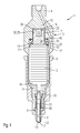
- a simplified schematic axial sectional view through the embodiment of a fuel injection valve according to the invention.
Nachfolgend wird ein Ausführungsbeispiel der Erfindung beispielhaft beschrieben.Hereinafter will be an embodiment of the invention described by way of example.
Ein in Fig. 1 in einer axialen Schnittdarstellung gezeigtes erfindungsgemäßes Brennstoffeinspritzventil 1 dient insbesondere zum direkten Einspritzen von Brennstoff in einen Brennraum einer gemischverdichtenden, fremdgezündeten Brennkraftmaschine.One shown in Fig. 1 in an axial sectional view Inventive fuel injection valve 1 is used in particular for the direct injection of fuel into a combustion chamber of a mixture-compressing, spark-ignited Internal combustion engine.
In jeweils einem ineinandergreifenden Gehäuseoberteil 4 und
einem koaxial dazu angeordneten Gehäuseunterteil 5 sind eine
Ventilnadel 8, ein Aktor 2, ein Düsenkörpers 6 und ein
hydraulischer Koppler 3 jeweils zueinander koaxial
angeordnet. Der Düsenkörper 6 durchgreift von Innen mit
seinem abströmseitigen Ende das abströmseitige Ende des
Gehäuseunterteils 5. Die Ventilnadel 8, welche wiederum den
Düsenkörper 6 am abströmseitigen Ende von Innen durch eine
Abspritzöffnung 12 durchgreift, weist an ihrem
abströmseitigen Ende einen Ventilschließkörper 7 auf,
welcher mit einer am abspritzseitigen Ende des Düsenkörpers
6 ausgebildeten Ventilsitzfläche 13 zu einem Dichtsitz
zusammenwirkt.In each case an interlocking housing
Der in der unteren Hälfte des Gehäuseoberteils 4 angeordnete
Aktor 2 steht mit der Ventilnadel 8 über einen Aktorkopf 10
und ein Zwischenstück 9, welches das Gehäuseoberteil 4 im
Bereich des abspritzseitigen Endes des Gehäuseoberteils 4
durchgreift, in Wirkverbindung.The arranged in the lower half of the
Ein spiralförmiges, um die Ventilnadel 8 umlaufendes erstes
Federelement 21 spannt die Ventilnadel 6 entgegen der
Abspritzrichtung vor. Das erste Federelement 21 ist dabei
zwischen einer im Düsenkörper 6 ausgebildeten Schulter 40
und einem zuströmseitig davon angeordneten, an der
Ventilnadel 8 fixierten Flansch 26 eingespannt. Die
Federkraft des ersten Federelements 21 zieht den
Ventilschließkörper 7 bei dem in diesem Ausführungsbeispiel
nach außen öffnenden Brennstoffeinspritzventil 1 in den
Dichtsitz.A spiral, around the
Der hydraulische Koppler 3 weist in diesem
Ausführungsbeispiel im wesentlichen einen ersten Koppler-Abschnitt
23 und einen zylinderförmigen zweiten Koppler-Abschnitt
24 auf. In diesem Ausführungsbeispiel bildet der
erste Koppler-Abschnitt 23 eine einseitig geschlossene, im
Gehäuseoberteil 4 eingebrachte, hohlzylindrische Form 17, in
die der zweite Koppler-Abschnitt 24 abströmseitig eingreift.
Ein zwischen dem Grund der Form 17 und der der Form 17
zugewandten Stirnseite des zweiten Abschnitts 24
befindliches Hydraulik-Volumen 36 ist durch die axiale
Verschiebbarkeit des zweiten Koppler-Abschnitts 24 gegenüber
dem ersten Koppler Abschnitt 23 variierbar. The
Der zweite Koppler-Abschnitt 24 ist im ersten Koppler-Abschnitt
23, bzw. in der Form 17, mit einem Spiel 32,
welches beispielsweise zwischen 2 und 10 Mikrometer beträgt
und durch einen Spalt 25 erzeugt ist, geführt. Das
Verhältnis der minimalen Eingreiftiefe des zweiten
Abschnitts 24 zu seinem Durchmesser ist so gewählt, daß sich
der zweite Abschnitt 24 in der Form 17 nicht verkanten kann.The
Zuströmseitig des Aktors 2 steht der Aktor 2 über einen
plattenförmigen, sich zuströmseitig durch eine zweite Stufe
43 nach oben verjüngenden Aktorfuß 11 mit dem
abströmseitigen Ende des zweiten Koppler-Abschnitts 24 in
Wirkverbindung. Der Durchmesser des Aktorfußes 2 ist größer
als der des zweiten Koppler-Abschnitts 24, wobei beide
Bauteile zueinander koaxial angeordnet sind. Ein in diesem
Ausführungsbeispiel als Spiralfeder ausgebildetes zweites
Federelement 20 läuft um den zweiten Koppler-Abschnitt 24 im
Bereich seines abströmseitigen Endes um. Das zweite
Federelement 20 drückt den Aktorfuß 11 mit einer Vorspannung
auf den Aktor 2, wobei sich das zweite Federelement 20
zuströmseitig an einer um die Form 17 umlaufenden ersten
Stufe 42 und abströmseitig an der zweiten Stufe 43 abstützt.On the upstream side of the
Ein in diesem Ausführungsbeispiel wellrohrförmiger, aus
Stahl bestehender und elastischer flexibler Abschnitt 27 ist
innerhalb des zweiten Federelements 20 angeordnet. Das
zuströmseitige Ende des flexiblen Abschnitts 20 ist im
Bereich der ersten Stufe 42 hermetisch dicht, beispielsweise
durch Schweißen, gefügt. Das abströmseitige Ende des
flexiblen Abschnitts 20 ist in der Nähe des Aktorfußes 11
seitlich am zweiten Koppler-Abschnitt 24 hermetisch dicht,
beispielsweise durch Schweißen gefügt. Der flexible
Abschnitt 27 verschließt den Spalt 25 und begrenzt zusammen
mit dem Bereich des abspritzseitigen Endes des zweiten
Koppler-Abschnitts 24 einen Ausgleichsraum 14. Der
Ausgleichsraum 14 ist durch den Spalt 25 mit dem Hydraulik-Volumen
36 verbunden. A wellrohrförmiger in this embodiment, from
Steel is existing and elastic
Im zweiten Koppler-Abschnitt 24 ist eine zum Hydraulik-Volumen
36 hin geöffnete Ausnehmung 16 angeordnet, welche
dem Hydraulik-Volumen 36 zugeordnet ist und in diesem
Ausführungsbeispiel hohlzylinderförmig ausgebildet ist. In
der Ausnehmung 16 ist ein der Form der Ausnehmung 16
ähnliches Ausgleichselement 15 angeordnet, wobei das
Ausgleichselement 15 nur in die Ausnehmung 16 eingelegt ist
und somit alle seine Außenflächen von Hydraulikmedium
umgeben sind. In anderen Ausführungsbeispielen kann das
Ausgleichselement 15 in der Ausnehmung 16 fixiert bzw.
gefügt sein, beispielsweise durch eine Schweißung am Boden
der Ausnehmung 16 oder eine formschlüssige Verbindung.In the
Das in der Ausnehmung 16 eingelegte, aus Invar-Stahl
bestehende Ausgleichselement 15 weist einen geringeren
Temperatur-Ausdehnungskoeffizienten auf als das
Hydraulikmedium und/oder die Materialien aus denen der erste
Koppler-Abschnitt 24 im Bereich des Hydraulik-Volumens 36
besteht. Da sich die für gewöhnlich verwendeten
Hydraulikmedien stärker ausdehnen als die Koppler-Abschnitte
23, 24, aber das Ausgleichselement 15 sich weniger stark
ausdehnt, gleicht das Ausgleichselement 15 die
unterschiedlichen Ausdehnungen der Koppler-Abschnitte 23, 24
und des Hydraulikmediums wenigsten teilweise aus.The inserted in the
In anderen Ausführungsbeispielen kann zumindest ein Teil des
ersten Koppler-Abschnitts 23, insbesondere im Bereich der
hohlzylindrischen Form 17 bzw. des Hydraulik-Volumens 36,
aus dem Ausgleichselement 15 bestehen. In diesem Fall weist
der beispielsweise aus Bronze, Messing, Aluminium oder einem
thermoplastischen Kunststoffmaterial bestehende Teil des
ersten Koppler-Abschnitts 23 einen Ausdehnungskoeffizienten
auf, der größer oder gleich dem des Hydraulikmediums ist.In other embodiments, at least a portion of the
In diesem Ausführungsbeispiel sind der Ausgleichsraum 14,
der Spalt 25 und das Hydraulik-Volumen 36 mit der Ausnehmung
16 vollständig mit einem ölartigen, gasfreien und
inkompressiblen Hydraulikmedium gefüllt. Der flexible
Abschnitt 27 ist durch die Auswahl der Materialien und/oder
durch eine Beschichtung diffusionsdicht und beaufschlagt das
Hydraulikmedium durch seine Elastizität mit einem Druck.In this embodiment, the
Wird der Aktor 2 über eine nicht dargestellte elektrische
Leitung erregt, so dehnt er sich schnell aus. Da das
Hydraulikmedium nicht schnell genug vom Hydraulik-Volumen 36
in den Ausgleichsraum 14 abfließen kann, verhält sich der
Koppler 3 sehr hart, wodurch die Längenausdehnung des Aktors
2 fast vollständig auf die Ventilnadel 8 wirkt. Die
Ventilnadel 8 wird entgegen der Vorspannkraft des ersten
Federelements 21 axial in Abspritzrichtung bewegt. Dadurch
öffnet der Dichtsitz und der über den nur teilweise
dargestellten Brennstoffkanal 22 druckbehaftet zugeleitete
Brennstoff wird über die Abspritzöffnung 12 in den nicht
dargestellten Brennraum abgespritzt. Langsame
Längenänderungen des Aktors 2 werden durch den Austausch von
Hydraulikmedium zwischen dem Hydraulik-Volumen 36 und dem
Ausgleichsraum 14 ausgeglichen.If the
Die Erfindung ist nicht auf die dargestellten Ausführungsbeispiele beschränkt und kann z. B. auch für nach innen öffnende Brennstoffeinspritzventile verwendet werden.The invention is not limited to those shown Embodiments limited and z. B. also for internal opening fuel injectors are used.
Claims (14)
dadurch gekennzeichnet, daß zumindest ein Ausgleichselement (15) die temperaturbedingten Volumenänderungen des Hydraulikmediums ausgleicht, wobei das Ausgleichselement (15) das Hydraulik-Volumen (36) wenigstens teilweise begrenzt und/oder im Hydraulik-Volumen (36) angeordnet ist.Fuel injection valve (1), in particular for direct injection of fuel into a combustion chamber of an internal combustion engine, with a piezoelectric, electrostrictive or magnetostrictive actuator (2), a valve closing body (7) operatively connected to the actuator (2) and having a valve seat surface (13 ) and a coupler (3) having a first coupler portion (23) and a second coupler portion (24), the two coupler portions (23, 24) being movable relative to each other and communicating with each other a hydraulic medium located in a hydraulic volume (36) are in operative connection, wherein the hydraulic volume (36) communicates with at least one compensation chamber (14) for exchanging hydraulic medium and at least one of the coupler sections (23, 24) with a game (32), which is formed by a gap (25) is guided,
characterized in that at least one compensating element (15) compensates for the temperature-induced volume changes of the hydraulic medium, wherein the compensating element (15) at least partially limits the hydraulic volume (36) and / or in the hydraulic volume (36).
dadurch gekennzeichnet, daß das Ausgleichselement (15) bei den Betriebstemperaturen des Brennstoffeinspritzventils (1), insbesondere zwischen 20° Celsius und 100° Celsius, einen festen Aggregatzustand aufweist.Fuel injection according to claim 1,
characterized in that the compensating element (15) at the operating temperatures of the fuel injection valve (1), in particular between 20 ° Celsius and 100 ° Celsius, has a solid state of matter.
dadurch gekennzeichnet, daß der erste Koppler-Abschnitt (23) durch eine einseitig geschlossene hohlzylindrische Form (17) gebildet ist, in den der zylindrisch ausgebildete zweite Koppler-Abschnitt (24) wenigstens teilweise eingreift und dabei den Spalt (25) bildet.Fuel injection valve according to claim 1 or 2,
characterized in that the first coupler section (23) is formed by a hollow cylindrical shape (17) closed on one side, in which the cylindrically shaped second coupler section (24) at least partially engages, thereby forming the gap (25).
dadurch gekennzeichnet,
das der zweite Koppler-Abschnitt (24) wenigstens teilweise aus dem Ausgleichselement (15) besteht.Fuel injection valve according to claim 3,
characterized
the second coupler section (24) consists at least partially of the compensating element (15).
dadurch gekennzeichnet, daß in zumindest einem der Koppler-Abschnitte (23, 24) zumindest eine zum Hydraulik-Volumen (36) unmittelbar geöffnete Ausnehmung (16) eingebracht ist und in der Ausnehmung (16) das zumindest eine Ausgleichselement (15) angeordnet ist.Fuel injection valve according to claim 3 or 4,
characterized in that in at least one of the coupler sections (23, 24) at least one to the hydraulic volume (36) immediately opened recess (16) is introduced and in the recess (16) the at least one compensating element (15) is arranged.
dadurch gekennzeichnet, daß die gesamte Außenfläche des Ausgleichselements (15) mit dem Hydraulikmedium in Kontakt steht.Fuel injection valve according to claim 5,
characterized in that the entire outer surface of the compensating element (15) is in contact with the hydraulic medium.
dadurch gekennzeichnet, daß das Ausgleichselement (15) einen geringeren Temperatur-Ausdehnungskoeffizienten aufweist als das Hydraulikmedium und/oder als die Materialien aus denen der erste Koppler-Abschnitt (24) im Bereich des Hydraulik-Volumens (36) besteht. Fuel injection valve according to one of claims 3 to 6,
characterized in that the compensating element (15) has a lower coefficient of thermal expansion than the hydraulic medium and / or as the materials of which the first coupler section (24) in the region of the hydraulic volume (36).
dadurch gekennzeichnet, daß das Ausgleichselement (15) aus Invar-Stahl besteht.Fuel injection valve according to one of claims 3 to 7,
characterized in that the compensating element (15) consists of invar steel.
dadurch gekennzeichnet, daß zumindest ein Teil des ersten Koppler-Abschnitts (23), insbesondere im Bereich der hohlzylindrischen Form (17), aus dem Ausgleichselement (15) besteht.Fuel injection valve according to claim 3,
characterized in that at least a part of the first coupler section (23), in particular in the region of the hollow cylindrical shape (17), consists of the compensating element (15).
dadurch gekennzeichnet, daß der Temperatur-Ausdehnungskoeffizient des Ausgleichselements (15) größer oder gleich dem des Hydraulikmediums ist.Fuel injection valve according to claim 9,
characterized in that the temperature expansion coefficient of the compensating element (15) is greater than or equal to that of the hydraulic medium.
dadurch gekennzeichnet, daß das Ausgleichselement (15) wenigstens teilweise aus einer Kupfer-Zinn-Legierung, Kupfer-Zink-Legierung, Aluminium oder einem thermoplastischen Werkstoff besteht.Fuel injection valve according to claim 9 or 10,
characterized in that the compensating element (15) consists at least partially of a copper-tin alloy, copper-zinc alloy, aluminum or a thermoplastic material.
dadurch gekennzeichnet, daß ein flexibler Abschnitt (27) einen Ausgleichsraum (14) wenigsten teilweise begrenzt.Fuel injection valve according to one of the preceding claims,
characterized in that a flexible portion (27) at least partially restricts a compensation space (14).
dadurch gekennzeichnet, daß der flexible Abschnitt (27) lochscheibenförmig oder wellrohrförmig ausgebildet ist.Fuel injection valve according to claim 12,
characterized in that the flexible portion (27) is formed hole-shaped or corrugated pipe.
dadurch gekennzeichnet, daß das Hydraulikmedium ein Öl oder Gel ist.Fuel injection valves according to one of the preceding claims,
characterized in that the hydraulic medium is an oil or gel.
Applications Claiming Priority (2)
| Application Number | Priority Date | Filing Date | Title |
|---|---|---|---|
| DE10345203 | 2003-09-29 | ||
| DE2003145203 DE10345203A1 (en) | 2003-09-29 | 2003-09-29 | Fuel injector |
Publications (2)
| Publication Number | Publication Date |
|---|---|
| EP1519037A1 true EP1519037A1 (en) | 2005-03-30 |
| EP1519037B1 EP1519037B1 (en) | 2006-07-05 |
Family
ID=34178010
Family Applications (1)
| Application Number | Title | Priority Date | Filing Date |
|---|---|---|---|
| EP20040104647 Expired - Fee Related EP1519037B1 (en) | 2003-09-29 | 2004-09-24 | Fuel injection valve |
Country Status (2)
| Country | Link |
|---|---|
| EP (1) | EP1519037B1 (en) |
| DE (2) | DE10345203A1 (en) |
Cited By (6)
| Publication number | Priority date | Publication date | Assignee | Title |
|---|---|---|---|---|
| EP1591656A2 (en) * | 2004-04-26 | 2005-11-02 | Isuzu Motors Limited | Differential expansion absorption mechanism and fuel injection valve comprising same |
| EP1705369A1 (en) * | 2005-03-01 | 2006-09-27 | Robert Bosch Gmbh | Fuel injector for internal combustion engines |
| EP1813805A1 (en) * | 2006-01-27 | 2007-08-01 | Siemens VDO Automotive S.p.A. | Compensation assembly for an injector |
| WO2012007311A1 (en) * | 2010-07-15 | 2012-01-19 | Siemens Aktiengesellschaft | Thermal volume-neutral stroke transmitter, especially for a dosing valve without hydraulic compensator |
| EP3118443A1 (en) * | 2015-07-15 | 2017-01-18 | Delphi International Operations Luxembourg S.à r.l. | Servo actuator for fuel injector |
| EP3139028A1 (en) | 2015-09-03 | 2017-03-08 | Delphi International Operations Luxembourg S.à r.l. | Double ended coupler for servo actuator |
Families Citing this family (1)
| Publication number | Priority date | Publication date | Assignee | Title |
|---|---|---|---|---|
| DE102008035087B4 (en) * | 2008-07-28 | 2015-02-12 | Continental Automotive Gmbh | Injector |
Citations (6)
| Publication number | Priority date | Publication date | Assignee | Title |
|---|---|---|---|---|
| DE3533085A1 (en) * | 1985-09-17 | 1987-03-26 | Bosch Gmbh Robert | METERING VALVE FOR DOSING LIQUIDS OR GASES |
| EP0869278A1 (en) * | 1997-04-04 | 1998-10-07 | Siemens Aktiengesellschaft | Piezoelectric injection valve with means to compensate for the thermal expansion of piezoelectric actuator |
| DE19727992A1 (en) * | 1997-07-01 | 1999-01-07 | Siemens Ag | Thermal expansion compensation element |
| WO2001023745A1 (en) * | 1999-09-30 | 2001-04-05 | Robert Bosch Gmbh | Valve for controlling liquids |
| WO2001025613A1 (en) * | 1999-10-02 | 2001-04-12 | Robert Bosch Gmbh | Fuel injection valve |
| US20020134851A1 (en) * | 2000-10-11 | 2002-09-26 | Jack Lorraine | Compensator assembly having a pressure responsive valve for a solid state actuator of a fuel injector |
Family Cites Families (3)
| Publication number | Priority date | Publication date | Assignee | Title |
|---|---|---|---|---|
| DE19940054C2 (en) * | 1999-08-24 | 2003-11-27 | Siemens Ag | Dosing valve for a pressurized fluid |
| DE19940055C1 (en) * | 1999-08-24 | 2001-04-05 | Siemens Ag | Dosing valve |
| DE19950760A1 (en) * | 1999-10-21 | 2001-04-26 | Bosch Gmbh Robert | Fuel injection valve esp. for fuel injection systems of IC engines with piezo-electric or magneto-strictive actuator and valve closing body operable by valve needle working with valve |
-
2003
- 2003-09-29 DE DE2003145203 patent/DE10345203A1/en not_active Withdrawn
-
2004
- 2004-09-24 EP EP20040104647 patent/EP1519037B1/en not_active Expired - Fee Related
- 2004-09-24 DE DE200450000909 patent/DE502004000909D1/en active Active
Patent Citations (6)
| Publication number | Priority date | Publication date | Assignee | Title |
|---|---|---|---|---|
| DE3533085A1 (en) * | 1985-09-17 | 1987-03-26 | Bosch Gmbh Robert | METERING VALVE FOR DOSING LIQUIDS OR GASES |
| EP0869278A1 (en) * | 1997-04-04 | 1998-10-07 | Siemens Aktiengesellschaft | Piezoelectric injection valve with means to compensate for the thermal expansion of piezoelectric actuator |
| DE19727992A1 (en) * | 1997-07-01 | 1999-01-07 | Siemens Ag | Thermal expansion compensation element |
| WO2001023745A1 (en) * | 1999-09-30 | 2001-04-05 | Robert Bosch Gmbh | Valve for controlling liquids |
| WO2001025613A1 (en) * | 1999-10-02 | 2001-04-12 | Robert Bosch Gmbh | Fuel injection valve |
| US20020134851A1 (en) * | 2000-10-11 | 2002-09-26 | Jack Lorraine | Compensator assembly having a pressure responsive valve for a solid state actuator of a fuel injector |
Cited By (11)
| Publication number | Priority date | Publication date | Assignee | Title |
|---|---|---|---|---|
| EP1591656A2 (en) * | 2004-04-26 | 2005-11-02 | Isuzu Motors Limited | Differential expansion absorption mechanism and fuel injection valve comprising same |
| EP1591656A3 (en) * | 2004-04-26 | 2005-11-23 | Isuzu Motors Limited | Differential expansion absorption mechanism and fuel injection valve comprising same |
| US7198202B2 (en) | 2004-04-26 | 2007-04-03 | Isuzu Motors Limited | Differential expansion absorption mechanism and fuel injection valve comprising same |
| EP1705369A1 (en) * | 2005-03-01 | 2006-09-27 | Robert Bosch Gmbh | Fuel injector for internal combustion engines |
| EP1813805A1 (en) * | 2006-01-27 | 2007-08-01 | Siemens VDO Automotive S.p.A. | Compensation assembly for an injector |
| WO2012007311A1 (en) * | 2010-07-15 | 2012-01-19 | Siemens Aktiengesellschaft | Thermal volume-neutral stroke transmitter, especially for a dosing valve without hydraulic compensator |
| CN102971522A (en) * | 2010-07-15 | 2013-03-13 | 西门子公司 | Thermal volume-neutral stroke transmitter, especially for a dosing valve without hydraulic compensator |
| CN102971522B (en) * | 2010-07-15 | 2015-04-29 | 西门子公司 | Thermal volume-neutral stroke transmitter, especially for a dosing valve without hydraulic compensator |
| US9587609B2 (en) | 2010-07-15 | 2017-03-07 | Siemens Aktiengesellschaft | Thermally volume-neutral stroke transmitter, in particular for metering valve without hydraulic compensator |
| EP3118443A1 (en) * | 2015-07-15 | 2017-01-18 | Delphi International Operations Luxembourg S.à r.l. | Servo actuator for fuel injector |
| EP3139028A1 (en) | 2015-09-03 | 2017-03-08 | Delphi International Operations Luxembourg S.à r.l. | Double ended coupler for servo actuator |
Also Published As
| Publication number | Publication date |
|---|---|
| DE502004000909D1 (en) | 2006-08-17 |
| DE10345203A1 (en) | 2005-05-04 |
| EP1519037B1 (en) | 2006-07-05 |
Similar Documents
| Publication | Publication Date | Title |
|---|---|---|
| EP1149237B2 (en) | Fuel injection valve | |
| WO1994019597A1 (en) | Fluid dosing device | |
| EP2414662B1 (en) | Hydraulic stroke transmitter or amplifier | |
| EP1519037B1 (en) | Fuel injection valve | |
| DE10217594A1 (en) | Fuel injection valve for IC engines has throttle gap formed by Laser/erosion drilling, and positioned separate from guide gaps, for cheaper fabrication of gaps | |
| EP1378657B1 (en) | Fuel injector | |
| DE10019764A1 (en) | Valve for controlling liquids has filler hollow chamber with choke body, high/system pressure lines opening at either end; system pressure is et by specifying choke bore, piston size | |
| EP1454056B1 (en) | Fuel injection valve | |
| EP1601868B1 (en) | Fuel-injection valve | |
| EP1519035A1 (en) | Fuel injection valve | |
| EP1538331B1 (en) | Fuel injection valve | |
| WO2004081372A1 (en) | Fuel injection valve | |
| EP2898212B1 (en) | Fuel injection valve | |
| EP1519034B1 (en) | Fuel injection valve | |
| EP1544454B1 (en) | Fuel injection valve | |
| EP1452727B1 (en) | Fuel injector | |
| DE10332090B4 (en) | Fuel injector | |
| DE10332088A1 (en) | Fuel injector for motor vehicle, has built in hydraulic coupler having multiple seals to prevent leakage over long operational life | |
| WO2005050001A1 (en) | Fuel-injection valve | |
| EP1450034B1 (en) | Fuel injector | |
| EP1406006B1 (en) | Fuel injection valve | |
| EP1491760B1 (en) | Fuel injector | |
| DE10232194B4 (en) | Fuel injector | |
| WO2006128751A1 (en) | Common rail injector | |
| DE102005045892A1 (en) | Directly driven fuel injector, comprises outwards opening jet needle moved by piezoelectric multi-layer device |
Legal Events
| Date | Code | Title | Description |
|---|---|---|---|
| PUAI | Public reference made under article 153(3) epc to a published international application that has entered the european phase |
Free format text: ORIGINAL CODE: 0009012 |
|
| AK | Designated contracting states |
Kind code of ref document: A1 Designated state(s): AT BE BG CH CY CZ DE DK EE ES FI FR GB GR HU IE IT LI LU MC NL PL PT RO SE SI SK TR |
|
| AX | Request for extension of the european patent |
Extension state: AL HR LT LV MK |
|
| 17P | Request for examination filed |
Effective date: 20050930 |
|
| AKX | Designation fees paid |
Designated state(s): DE FR GB IT |
|
| GRAP | Despatch of communication of intention to grant a patent |
Free format text: ORIGINAL CODE: EPIDOSNIGR1 |
|
| GRAS | Grant fee paid |
Free format text: ORIGINAL CODE: EPIDOSNIGR3 |
|
| GRAA | (expected) grant |
Free format text: ORIGINAL CODE: 0009210 |
|
| AK | Designated contracting states |
Kind code of ref document: B1 Designated state(s): DE FR GB IT |
|
| REG | Reference to a national code |
Ref country code: GB Ref legal event code: FG4D Free format text: NOT ENGLISH |
|
| REF | Corresponds to: |
Ref document number: 502004000909 Country of ref document: DE Date of ref document: 20060817 Kind code of ref document: P |
|
| GBT | Gb: translation of ep patent filed (gb section 77(6)(a)/1977) |
Effective date: 20061006 |
|
| ET | Fr: translation filed | ||
| PLBE | No opposition filed within time limit |
Free format text: ORIGINAL CODE: 0009261 |
|
| STAA | Information on the status of an ep patent application or granted ep patent |
Free format text: STATUS: NO OPPOSITION FILED WITHIN TIME LIMIT |
|
| 26N | No opposition filed |
Effective date: 20070410 |
|
| PGFP | Annual fee paid to national office [announced via postgrant information from national office to epo] |
Ref country code: GB Payment date: 20140923 Year of fee payment: 11 |
|
| PGFP | Annual fee paid to national office [announced via postgrant information from national office to epo] |
Ref country code: IT Payment date: 20140924 Year of fee payment: 11 |
|
| PGFP | Annual fee paid to national office [announced via postgrant information from national office to epo] |
Ref country code: FR Payment date: 20140917 Year of fee payment: 11 |
|
| PG25 | Lapsed in a contracting state [announced via postgrant information from national office to epo] |
Ref country code: IT Free format text: LAPSE BECAUSE OF NON-PAYMENT OF DUE FEES Effective date: 20150924 |
|
| GBPC | Gb: european patent ceased through non-payment of renewal fee |
Effective date: 20150924 |
|
| REG | Reference to a national code |
Ref country code: FR Ref legal event code: ST Effective date: 20160531 |
|
| PG25 | Lapsed in a contracting state [announced via postgrant information from national office to epo] |
Ref country code: GB Free format text: LAPSE BECAUSE OF NON-PAYMENT OF DUE FEES Effective date: 20150924 |
|
| PG25 | Lapsed in a contracting state [announced via postgrant information from national office to epo] |
Ref country code: FR Free format text: LAPSE BECAUSE OF NON-PAYMENT OF DUE FEES Effective date: 20150930 |
|
| PGFP | Annual fee paid to national office [announced via postgrant information from national office to epo] |
Ref country code: DE Payment date: 20171128 Year of fee payment: 14 |
|
| REG | Reference to a national code |
Ref country code: DE Ref legal event code: R119 Ref document number: 502004000909 Country of ref document: DE |
|
| PG25 | Lapsed in a contracting state [announced via postgrant information from national office to epo] |
Ref country code: DE Free format text: LAPSE BECAUSE OF NON-PAYMENT OF DUE FEES Effective date: 20190402 |