EP1519014A2 - Corrosion protection liner for a flue gas filter and method for the renovation of flue gas filters - Google Patents
Corrosion protection liner for a flue gas filter and method for the renovation of flue gas filters Download PDFInfo
- Publication number
- EP1519014A2 EP1519014A2 EP04014641A EP04014641A EP1519014A2 EP 1519014 A2 EP1519014 A2 EP 1519014A2 EP 04014641 A EP04014641 A EP 04014641A EP 04014641 A EP04014641 A EP 04014641A EP 1519014 A2 EP1519014 A2 EP 1519014A2
- Authority
- EP
- European Patent Office
- Prior art keywords
- flue gas
- filter
- wall
- layer
- gas filter
- Prior art date
- Legal status (The legal status is an assumption and is not a legal conclusion. Google has not performed a legal analysis and makes no representation as to the accuracy of the status listed.)
- Granted
Links
- UGFAIRIUMAVXCW-UHFFFAOYSA-N Carbon monoxide Chemical compound [O+]#[C-] UGFAIRIUMAVXCW-UHFFFAOYSA-N 0.000 title claims abstract description 77
- 239000003546 flue gas Substances 0.000 title claims abstract description 77
- 238000000034 method Methods 0.000 title claims description 11
- 238000005260 corrosion Methods 0.000 title abstract description 20
- 230000007797 corrosion Effects 0.000 title abstract description 19
- 238000009418 renovation Methods 0.000 title description 5
- 239000007789 gas Substances 0.000 claims abstract description 13
- 229920002430 Fibre-reinforced plastic Polymers 0.000 claims abstract description 5
- 239000011151 fibre-reinforced plastic Substances 0.000 claims abstract description 5
- 239000011248 coating agent Substances 0.000 claims description 21
- 238000000576 coating method Methods 0.000 claims description 21
- 125000006850 spacer group Chemical group 0.000 claims description 12
- 239000002131 composite material Substances 0.000 claims description 10
- 239000004744 fabric Substances 0.000 claims description 10
- 238000009422 external insulation Methods 0.000 claims description 7
- 230000008439 repair process Effects 0.000 claims description 7
- 230000008859 change Effects 0.000 claims description 4
- 230000008569 process Effects 0.000 claims description 4
- 238000005067 remediation Methods 0.000 claims description 2
- 150000001875 compounds Chemical class 0.000 abstract 1
- QAOWNCQODCNURD-UHFFFAOYSA-N Sulfuric acid Chemical compound OS(O)(=O)=O QAOWNCQODCNURD-UHFFFAOYSA-N 0.000 description 19
- 229910000831 Steel Inorganic materials 0.000 description 9
- 239000010959 steel Substances 0.000 description 9
- 239000007787 solid Substances 0.000 description 4
- 239000003351 stiffener Substances 0.000 description 4
- 230000007704 transition Effects 0.000 description 4
- 239000002253 acid Substances 0.000 description 3
- 238000004140 cleaning Methods 0.000 description 3
- 239000000428 dust Substances 0.000 description 3
- 238000010438 heat treatment Methods 0.000 description 3
- 238000009413 insulation Methods 0.000 description 3
- 239000006223 plastic coating Substances 0.000 description 3
- OKTJSMMVPCPJKN-UHFFFAOYSA-N Carbon Chemical compound [C] OKTJSMMVPCPJKN-UHFFFAOYSA-N 0.000 description 2
- 230000008901 benefit Effects 0.000 description 2
- 238000009833 condensation Methods 0.000 description 2
- 230000005494 condensation Effects 0.000 description 2
- 239000003344 environmental pollutant Substances 0.000 description 2
- 239000000463 material Substances 0.000 description 2
- 239000002245 particle Substances 0.000 description 2
- 231100000719 pollutant Toxicity 0.000 description 2
- 239000002699 waste material Substances 0.000 description 2
- 239000002535 acidifier Substances 0.000 description 1
- 238000004873 anchoring Methods 0.000 description 1
- 239000010425 asbestos Substances 0.000 description 1
- 230000009286 beneficial effect Effects 0.000 description 1
- 230000001419 dependent effect Effects 0.000 description 1
- 150000002013 dioxins Chemical class 0.000 description 1
- 239000012717 electrostatic precipitator Substances 0.000 description 1
- 150000002240 furans Chemical class 0.000 description 1
- 239000003365 glass fiber Substances 0.000 description 1
- 239000011491 glass wool Substances 0.000 description 1
- 229910001385 heavy metal Inorganic materials 0.000 description 1
- 238000009421 internal insulation Methods 0.000 description 1
- 238000002955 isolation Methods 0.000 description 1
- 230000002045 lasting effect Effects 0.000 description 1
- 238000005192 partition Methods 0.000 description 1
- 239000004033 plastic Substances 0.000 description 1
- 229920003023 plastic Polymers 0.000 description 1
- 238000002360 preparation method Methods 0.000 description 1
- 230000009467 reduction Effects 0.000 description 1
- 238000009419 refurbishment Methods 0.000 description 1
- 229910052895 riebeckite Inorganic materials 0.000 description 1
- 229920003002 synthetic resin Polymers 0.000 description 1
- 239000000057 synthetic resin Substances 0.000 description 1
- 238000001931 thermography Methods 0.000 description 1
Images
Classifications
-
- F—MECHANICAL ENGINEERING; LIGHTING; HEATING; WEAPONS; BLASTING
- F01—MACHINES OR ENGINES IN GENERAL; ENGINE PLANTS IN GENERAL; STEAM ENGINES
- F01N—GAS-FLOW SILENCERS OR EXHAUST APPARATUS FOR MACHINES OR ENGINES IN GENERAL; GAS-FLOW SILENCERS OR EXHAUST APPARATUS FOR INTERNAL COMBUSTION ENGINES
- F01N3/00—Exhaust or silencing apparatus having means for purifying, rendering innocuous, or otherwise treating exhaust
- F01N3/01—Exhaust or silencing apparatus having means for purifying, rendering innocuous, or otherwise treating exhaust by means of electric or electrostatic separators
-
- B—PERFORMING OPERATIONS; TRANSPORTING
- B01—PHYSICAL OR CHEMICAL PROCESSES OR APPARATUS IN GENERAL
- B01D—SEPARATION
- B01D46/00—Filters or filtering processes specially modified for separating dispersed particles from gases or vapours
- B01D46/0027—Filters or filtering processes specially modified for separating dispersed particles from gases or vapours with additional separating or treating functions
- B01D46/0036—Filters or filtering processes specially modified for separating dispersed particles from gases or vapours with additional separating or treating functions by adsorption or absorption
-
- B—PERFORMING OPERATIONS; TRANSPORTING
- B01—PHYSICAL OR CHEMICAL PROCESSES OR APPARATUS IN GENERAL
- B01D—SEPARATION
- B01D46/00—Filters or filtering processes specially modified for separating dispersed particles from gases or vapours
- B01D46/02—Particle separators, e.g. dust precipitators, having hollow filters made of flexible material
-
- B—PERFORMING OPERATIONS; TRANSPORTING
- B01—PHYSICAL OR CHEMICAL PROCESSES OR APPARATUS IN GENERAL
- B01D—SEPARATION
- B01D46/00—Filters or filtering processes specially modified for separating dispersed particles from gases or vapours
- B01D46/42—Auxiliary equipment or operation thereof
- B01D46/48—Removing dust other than cleaning filters, e.g. by using collecting trays
-
- B—PERFORMING OPERATIONS; TRANSPORTING
- B01—PHYSICAL OR CHEMICAL PROCESSES OR APPARATUS IN GENERAL
- B01D—SEPARATION
- B01D46/00—Filters or filtering processes specially modified for separating dispersed particles from gases or vapours
- B01D46/56—Filters or filtering processes specially modified for separating dispersed particles from gases or vapours with multiple filtering elements, characterised by their mutual disposition
- B01D46/58—Filters or filtering processes specially modified for separating dispersed particles from gases or vapours with multiple filtering elements, characterised by their mutual disposition connected in parallel
-
- F—MECHANICAL ENGINEERING; LIGHTING; HEATING; WEAPONS; BLASTING
- F01—MACHINES OR ENGINES IN GENERAL; ENGINE PLANTS IN GENERAL; STEAM ENGINES
- F01N—GAS-FLOW SILENCERS OR EXHAUST APPARATUS FOR MACHINES OR ENGINES IN GENERAL; GAS-FLOW SILENCERS OR EXHAUST APPARATUS FOR INTERNAL COMBUSTION ENGINES
- F01N13/00—Exhaust or silencing apparatus characterised by constructional features ; Exhaust or silencing apparatus, or parts thereof, having pertinent characteristics not provided for in, or of interest apart from, groups F01N1/00 - F01N5/00, F01N9/00, F01N11/00
- F01N13/14—Exhaust or silencing apparatus characterised by constructional features ; Exhaust or silencing apparatus, or parts thereof, having pertinent characteristics not provided for in, or of interest apart from, groups F01N1/00 - F01N5/00, F01N9/00, F01N11/00 having thermal insulation
-
- F—MECHANICAL ENGINEERING; LIGHTING; HEATING; WEAPONS; BLASTING
- F01—MACHINES OR ENGINES IN GENERAL; ENGINE PLANTS IN GENERAL; STEAM ENGINES
- F01N—GAS-FLOW SILENCERS OR EXHAUST APPARATUS FOR MACHINES OR ENGINES IN GENERAL; GAS-FLOW SILENCERS OR EXHAUST APPARATUS FOR INTERNAL COMBUSTION ENGINES
- F01N3/00—Exhaust or silencing apparatus having means for purifying, rendering innocuous, or otherwise treating exhaust
- F01N3/02—Exhaust or silencing apparatus having means for purifying, rendering innocuous, or otherwise treating exhaust for cooling, or for removing solid constituents of, exhaust
- F01N3/021—Exhaust or silencing apparatus having means for purifying, rendering innocuous, or otherwise treating exhaust for cooling, or for removing solid constituents of, exhaust by means of filters
- F01N3/0212—Exhaust or silencing apparatus having means for purifying, rendering innocuous, or otherwise treating exhaust for cooling, or for removing solid constituents of, exhaust by means of filters with one or more perforated tubes surrounded by filtering material, e.g. filter candles
-
- F—MECHANICAL ENGINEERING; LIGHTING; HEATING; WEAPONS; BLASTING
- F23—COMBUSTION APPARATUS; COMBUSTION PROCESSES
- F23J—REMOVAL OR TREATMENT OF COMBUSTION PRODUCTS OR COMBUSTION RESIDUES; FLUES
- F23J15/00—Arrangements of devices for treating smoke or fumes
- F23J15/02—Arrangements of devices for treating smoke or fumes of purifiers, e.g. for removing noxious material
- F23J15/022—Arrangements of devices for treating smoke or fumes of purifiers, e.g. for removing noxious material for removing solid particulate material from the gasflow
- F23J15/025—Arrangements of devices for treating smoke or fumes of purifiers, e.g. for removing noxious material for removing solid particulate material from the gasflow using filters
-
- F—MECHANICAL ENGINEERING; LIGHTING; HEATING; WEAPONS; BLASTING
- F01—MACHINES OR ENGINES IN GENERAL; ENGINE PLANTS IN GENERAL; STEAM ENGINES
- F01N—GAS-FLOW SILENCERS OR EXHAUST APPARATUS FOR MACHINES OR ENGINES IN GENERAL; GAS-FLOW SILENCERS OR EXHAUST APPARATUS FOR INTERNAL COMBUSTION ENGINES
- F01N2310/00—Selection of sound absorbing or insulating material
- F01N2310/14—Wire mesh fabric, woven glass cloth or the like
-
- F—MECHANICAL ENGINEERING; LIGHTING; HEATING; WEAPONS; BLASTING
- F01—MACHINES OR ENGINES IN GENERAL; ENGINE PLANTS IN GENERAL; STEAM ENGINES
- F01N—GAS-FLOW SILENCERS OR EXHAUST APPARATUS FOR MACHINES OR ENGINES IN GENERAL; GAS-FLOW SILENCERS OR EXHAUST APPARATUS FOR INTERNAL COMBUSTION ENGINES
- F01N2450/00—Methods or apparatus for fitting, inserting or repairing different elements
- F01N2450/40—Retrofitting exhaust apparatus
-
- F—MECHANICAL ENGINEERING; LIGHTING; HEATING; WEAPONS; BLASTING
- F23—COMBUSTION APPARATUS; COMBUSTION PROCESSES
- F23J—REMOVAL OR TREATMENT OF COMBUSTION PRODUCTS OR COMBUSTION RESIDUES; FLUES
- F23J2217/00—Intercepting solids
- F23J2217/10—Intercepting solids by filters
- F23J2217/101—Baghouse type
-
- F—MECHANICAL ENGINEERING; LIGHTING; HEATING; WEAPONS; BLASTING
- F23—COMBUSTION APPARATUS; COMBUSTION PROCESSES
- F23J—REMOVAL OR TREATMENT OF COMBUSTION PRODUCTS OR COMBUSTION RESIDUES; FLUES
- F23J2900/00—Special arrangements for conducting or purifying combustion fumes; Treatment of fumes or ashes
- F23J2900/13001—Preventing or reducing corrosion in chimneys
-
- Y—GENERAL TAGGING OF NEW TECHNOLOGICAL DEVELOPMENTS; GENERAL TAGGING OF CROSS-SECTIONAL TECHNOLOGIES SPANNING OVER SEVERAL SECTIONS OF THE IPC; TECHNICAL SUBJECTS COVERED BY FORMER USPC CROSS-REFERENCE ART COLLECTIONS [XRACs] AND DIGESTS
- Y02—TECHNOLOGIES OR APPLICATIONS FOR MITIGATION OR ADAPTATION AGAINST CLIMATE CHANGE
- Y02T—CLIMATE CHANGE MITIGATION TECHNOLOGIES RELATED TO TRANSPORTATION
- Y02T10/00—Road transport of goods or passengers
- Y02T10/10—Internal combustion engine [ICE] based vehicles
- Y02T10/12—Improving ICE efficiencies
Definitions
- the present invention relates to a corrosion protection with the features of the preamble of claim 1 and a method for the renovation of flue gas filters.
- Flue gas filters are used, for example, in power plants and in Waste incinerators used to contain flue gas Pollutants such as dioxins, furans, heavy metals and solids withhold.
- flue gas filters in the Installed exhaust duct of the power plant.
- two Types of flue gas filters known, namely the so-called Cloth filter and the electrostatic filter.
- Cloth filter two Types of flue gas filters known, namely the so-called Cloth filter and the electrostatic filter.
- These filters are attachments with large dimensions, for example with a total height around 15 meters and a floor area of about 10x10 meters.
- the filters are made of a normal steel, the has no special corrosion properties.
- the filter is thermally insulated from the outside and partially heated. In this way it should be achieved that sets in the filter by the high temperature of the incoming raw gas, a temperature level that is above the acid dew point of sulfuric acid in the entire filter. This acid dew point is the resulting exhaust qualities in the range of 110 ° C to 160 ° C.
- the filter wall on its inside a lining from a layer composite with at least two layers of a fiber reinforced plastic and at least one between the Layers arranged cavity, which is with cold bridges provided filter wall of the flue gas facing Spaced inside. Between the inside and the Filter wall forms a temperature gradient, the not locally reduced by cold spots.
- the layer composite preferably comprises a spacer fabric, which is commercially available and which process reliable too is process.
- a preferred layer structure provides that is applied to the filter wall outer layer of GfK laminate is provided which has a spacer layer applied thereto made of GRP laminate with spacer fabric and one on this in turn applied, the flue gas facing inner layer also made of GRP laminate.
- the inner layer and Outer layer preferably have a thickness of 1.5 mm up to 3 mm.
- the spacer layer is preferably 4 mm to 9 mm thick.
- the lining is led into the raw gas inlet.
- wall sections the flue gas filter, the no temperature gradient subject to ambient temperature, with a simple Coating made of GRP laminate are provided.
- Such wall sections are, for example, as partitions between two directly adjacent flue gas filters to Find.
- the inventively provided layer composite and the proposed in this embodiment simple coating are seamlessly adjacent to each other finished. It is further suggested that the cavity of the Layer composite is not aerated, so in case of leaks or porosities in the layer composite only one pressure drop enters the cavity, but not a significant Leakage through the cavity is created.
- the procedure for remediation of a flue gas filter looks first the repair or replacement of the filter wall in front. After repair or replacement of the filter wall
- the cavity may in a further step with at least a connection for a pressure measuring device provided which detects a pressure change in the cavity.
- a pressure change would be a leakage in case of damage the flue gas facing layer of the layer composite display without this leakage leading to a leakage current.
- an existing external insulation of the Filter wall removed, making this wall accessible from the outside becomes.
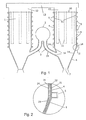
- FIG. 1 shows a typical filter system for cleaning illustrated by flue gas of a waste incinerator.
- the plant comprises two flue gas filters 1 of the type a cloth filter with flue gas from a flue gas channel 2 via a respective flue gas inlet 3 are acted upon.
- the two Flue gas filters 1 are substantially identical, so that the following description on the right in Figure 1 flue gas filter should be limited.
- the filter 1 has a wall 4 made of normal steel which forms four vertical outer walls of the filter.
- the Wall 4 is reinforced on the outside with stiffeners 5.
- These stiffeners 5 are circumferentially in the horizontal direction executed the flue gas filter 1. They take the externally acting atmospheric pressure forces caused by the im Flue gas filter an existing vacuum of about 100 millibars arise against the atmospheric pressure.
- the flue gas then enters through the lateral surface of the filter tubes 11 and upwards through the floor, designed like a tube bottom 10 in the clean gas collection channel 12 and the clean gas outlet 13th Pollutants, especially the dust load of example 1 Gram of dust per cubic meter is returned in the filter bags held.
- Pollutants especially the dust load of example 1 Gram of dust per cubic meter is returned in the filter bags held.
- the adhering dust falls down in the discharge cone 6, where he transported away from a scraper conveyor 7 becomes.
- the internal insulation 14 of the flue gas filter 1 causes in the mentioned materials and dimensions about a temperature gradient of 60 ° C at a flue gas temperature of 200 ° C. This temperature gradient is sufficient to safely Make that on the inner surface of the coating 14 at no point below the acid dew point. From the outside acting cold bridges, as in the area of stiffening 5 in particular by there mounted, made of steel Anchoring devices with an outer building arise can, are in this structure on the "cold" side the coating 14, which is not exposed to flue gas. A condensation of sulfuric acid is thus practically not possible.
- Plastic coatings that have these beneficial corrosion properties have so far failed in flue gas filters the type described are used. These plastic coatings keep their tightness and firmness Contact the underlying steel surface only up to a temperature of about 180 ° C certainly at. In flue gas filters However, depending on the operating conditions, fluctuating temperatures occur with peak temperatures of up to 250 ° C. These temperatures would make a simple plastic coating, too GfK laminate, destroy. In the described layer structure For example, the outer layer 24 may readily with temperatures for a short time be applied to 250 ° C, since the thereby entering Embrittlement of the plastic content for the function of Coating is harmless. The mechanical strength becomes This does not significantly affect. The contact to the underlying steel sheet is also not affected, since this area (the transition area between the Wall 4 and the first layer 21 in Figure 2) with far lower temperature peaks is applied.
- Another advantage of the flue gas filter according to the invention is in that the inner surface in the area of the discharge cone 6 compared to the conventional design in Sheet steel is very smooth. This smooth surface guarantees together with the lack of condensation a very effective Discharge of falling from the filter bags 11 solid particles. These particles slip reliably on the discharge cone 6 on the conveyor 7 from. In conventional systems comes there is adhesion of solids in the region of the discharge cone, the onset of sulfuric acid this sulfuric acid Soak up and thus locally a lasting effect of sulfuric acid on the wall of the Austragskonus cause. This is why the discharge cone in plants is particularly important According to the state of the art considerably endangered by corrosion.
- the coating of the flue gas filter according to the invention forms a substantially continuous, hermetically sealed Cavity.
- This cavity can with one or more connections be provided for measuring devices.
- a Pressure gauge connected, which responds to pressure changes and thus a possible damage to the inner part of the Coating 24 indicates.
- the cavity 23 goes directly to the pressure level, which prevails within the flue gas filter 1.
- These Pressure difference of about 100 millibars to the ambient pressure safely and quickly detectable.
- the pressure gauge thus shows any damage to the inner layer 24 reliably.
- the Coating can thus be easily monitored. Even with a leak, the flue gas filter 1 a To be operated for a while. The leak leads not to the increased sulfuric acid inside the flue gas filter 1 condensed.
- Flue gas filters become a corrosion-damaged flue gas filter initially repaired in the area of its wall 4. These are attacked by corrosion or destroyed Replaces sections of the wall.
- the external insulation as well as the external heating of a built according to the prior art The flue gas filter should be completely or partially removed.
- the discharge cone 6 and optionally also the flue gas inlets 3 have been repaired may be a coating 14 having the properties described above mounted on the inside of the flue gas filter become. This coating then has the above-described Characteristics and reliably prevents re-corrosion the steel sheet wall of the renovated flue gas filter. Renovating the external insulation and heating is no longer required, so the renovation with internal Coating not or slightly more expensive is as the restoration of the original state.
- the coating be applied completely or even in sections.
- the layer thickness or the layer structure can be dependent vary from the operating parameters.
Landscapes
- Engineering & Computer Science (AREA)
- Chemical & Material Sciences (AREA)
- Mechanical Engineering (AREA)
- General Engineering & Computer Science (AREA)
- Chemical Kinetics & Catalysis (AREA)
- Combustion & Propulsion (AREA)
- Filtering Of Dispersed Particles In Gases (AREA)
- Filtering Materials (AREA)
Abstract
Description
Die vorliegende Erfindung betrifft einen Korrosionsschutz mit
den Merkmalen des Oberbegriffs des Anspruchs 1 und ein Verfahren
zur Sanierung von Rauchgasfiltern.The present invention relates to a corrosion protection with
the features of the preamble of
Rauchgasfilter werden beispielsweise bei Kraftwerken und in Müllverbrennungsanlagen eingesetzt, um im Rauchgas enthaltene Schadstoffe wie Dioxine, Furane, Schwermetalle und Feststoffe zurückzuhalten. Zu diesem Zweck werden Rauchgasfilter in den Abgaskanal des Kraftwerks eingebaut. Insbesondere sind zwei Bauarten von Rauchgasfiltern bekannt, nämlich die sogenannten Tuchfilter und die Elektrofilter. Diese Filter sind Anlagen mit großen Abmessungen, beispielsweise mit einer Höhe von insgesamt rund 15 Metern und einer Grundfläche von etwa 10x10 Metern. Die Filter werden aus einem Normalstahl gefertigt, der keine besonderen Korrosionseigenschaften aufweist.Flue gas filters are used, for example, in power plants and in Waste incinerators used to contain flue gas Pollutants such as dioxins, furans, heavy metals and solids withhold. For this purpose, flue gas filters in the Installed exhaust duct of the power plant. In particular, two Types of flue gas filters known, namely the so-called Cloth filter and the electrostatic filter. These filters are attachments with large dimensions, for example with a total height around 15 meters and a floor area of about 10x10 meters. The filters are made of a normal steel, the has no special corrosion properties.
Zum Korrosionsschutz gegenüber im Rauchgas enthaltenen Säurebildner (SO3) wird nach dem Stand der Technik der Filter von außen thermisch isoliert und teilweise beheizt. Auf diese Weise soll erreicht werden, dass sich in dem Filter durch die hohe Temperatur des eintretenden Rohgases ein Temperaturniveau einstellt, das im gesamten Filter über dem Säuretaupunkt von Schwefelsäure liegt. Dieser Säuretaupunkt liegt bei den anfallenden Abgasqualitäten im Bereich von 110°C bis 160°C.For corrosion protection against acidifying agent (SO 3 ) contained in the flue gas, according to the prior art, the filter is thermally insulated from the outside and partially heated. In this way it should be achieved that sets in the filter by the high temperature of the incoming raw gas, a temperature level that is above the acid dew point of sulfuric acid in the entire filter. This acid dew point is the resulting exhaust qualities in the range of 110 ° C to 160 ° C.
In der Praxis zeigt sich jedoch, dass Kältebrücken zwischen dem Stahlmantel des Filters und nach außen geführten Tragkonstruktionen entstehen, die genau im Bereich der Kältebrücken zu einer Taupunktsunterschreitung führen. An diesen Stellen bildet sich Schwefelsäure, die im Bereich dieser Tragkonstruktionen Korrosion an der Filterwandung hervorruft. Andererseits läuft die entstehende Schwefelsäure auch an der Wandung herunter und führt zu Korrosion an dem unteren Austragskegel des Filtergehäuses. In diesem Bereich bildet sich zusammen mit dort anhaftenden Feststoffen eine besonders korrosionsfördernde Anhaftung, die innerhalb kurzer Zeit zu einer Korrosion der Filterwandung führt.In practice, however, shows that cold spots between the steel jacket of the filter and outwardly guided supporting structures emerge, which is exactly in the area of cold spots lead to a dew point below. In these places Sulfuric acid forms in the area of these supporting structures Corrosion on the filter wall causes. on the other hand The resulting sulfuric acid also runs down the wall and causes corrosion on the lower discharge cone of the Filter housing. In this area forms together with there adhering solids a particularly corrosive Adhesion, which in a short time leads to corrosion of the Filter wall leads.
Aufgrund der außen angeordneten Isolation der bekannten Rauchgasfilter, die üblicherweise aus Glaswolle besteht und zum Teil auch Asbest enthält, ist die durch Korrosion entstehende Leckage nicht unmittelbar erkennbar. Es zeigt sich lediglich ein Leckstrom in den mit Unterdruck betriebenen Filter hinein. Eine Sanierung ist dann fällig, wenn der Leckstrom zu groß wird. Die Sanierung umfasst das Entfernen der gesamten äußeren Isolation und nach erfolgter Instandsetzung des Filtermantels das erneute Anbringen einer Isolation. Diese Sanierung ist außerordentlich aufwendig und führt zu Stillstandszeiten.Due to the external insulation of the known flue gas filters, which is usually made of glass wool and the Part also contains asbestos, which is due to corrosion Leakage not immediately recognizable. It only shows a leakage into the vacuum operated filter. A refurbishment is due when the leakage current is too large becomes. The renovation involves removing the entire outer Isolation and after repair of the filter jacket re-attaching an insulation. This renovation is extraordinary consuming and leads to downtime.
Es ist deshalb Aufgabe der Erfindung, einen Rauchgasfilter mit einem verbesserten Korrosionsschutz zur Verfügung zu stellen und außerdem ein Verfahren zur Sanierung von bestehenden, durch Korrosion geschädigten Rauchgasfiltern zu schaffen.It is therefore an object of the invention to provide a flue gas filter to provide improved corrosion protection and also a process for the rehabilitation of existing, created by corrosion damaged flue gas filters.
Diese Aufgabe wird von einer Korrosionsschutzauskleidung mit
den Merkmalen des Anspruchs 1 und von einem Verfahren mit den
Merkmalen des Anspruchs 9 gelöst.This task is accompanied by a corrosion protection lining
the features of
Weil die Filterwandung an ihrer Innenseite eine Auskleidung aus einem Schichtenverbund mit wenigsten zwei Schichten eines faserverstärkten Kunststoffs und wenigstens einem zwischen den Schichten angeordneten Hohlraum aufweist, ist die mit Kältebrücken versehene Filterwandung von der dem Rauchgas zugewandten Innenseite beabstandet. Zwischen der Innenseite und der Filterwandung bildet sich ein Temperaturgradient aus, der nicht lokal durch Kältebrücken verringert wird.Because the filter wall on its inside a lining from a layer composite with at least two layers of a fiber reinforced plastic and at least one between the Layers arranged cavity, which is with cold bridges provided filter wall of the flue gas facing Spaced inside. Between the inside and the Filter wall forms a temperature gradient, the not locally reduced by cold spots.
Der Schichtenverbund umfasst vorzugsweise ein Abstandsgewebe, das kommerziell verfügbar ist und welches prozesssicher zu verarbeiten ist. Ein bevorzugter Schichtenaufbau sieht vor, dass eine auf die Filterwandung aufgebrachte Außenschicht aus GfK-Laminat vorgesehen ist, die eine darauf aufgebrachte Abstandsschicht aus GfK-Laminat mit Abstandsgewebe und eine auf diese wiederum aufgetragene, dem Rauchgas zugewandte Innenschicht ebenfalls aus GfK-Laminat auf. Die Innenschicht und Außenschicht weisen dabei vorzugsweise eine Dicke von 1,5 mm bis 3 mm auf. Die Abstandsschicht ist bevorzugt 4 mm bis 9 mm dick.The layer composite preferably comprises a spacer fabric, which is commercially available and which process reliable too is process. A preferred layer structure provides that is applied to the filter wall outer layer of GfK laminate is provided which has a spacer layer applied thereto made of GRP laminate with spacer fabric and one on this in turn applied, the flue gas facing inner layer also made of GRP laminate. The inner layer and Outer layer preferably have a thickness of 1.5 mm up to 3 mm. The spacer layer is preferably 4 mm to 9 mm thick.
Für einen besonders guten Korrosionsschutz ist vorzugsweise die Auskleidung bis in den Rohgaseinlass hineingeführt. Eine besonders kostengünstige Ausführung ergibt sich, wenn Wandungsabschnitte des Rauchgasfilters, die keinem Temperaturgradienten zur Umgebungstemperatur unterliegen, mit einer einfachen Beschichtung aus GfK-Laminat versehen sind. Solche Wandungsabschnitte sind beispielsweise als Trennwände zwischen zwei unmittelbar aneinander angrenzenden Rauchgasfiltern zu finden. Der erfindungsgemäß vorgesehene Schichtenverbund und die in diesem Ausführungsbeispiel vorgeschlagene einfache Beschichtung sind unterbrechungsfrei aneinander angrenzend zu fertigen. Es wird weiter vorgeschlagen, dass der Hohlraum des Schichtenverbundes nicht durchlüftet ist, so dass bei Leckagen oder Porositäten in dem Schichtenverbund lediglich ein Druckabfall in dem Hohlraum eintritt, nicht aber ein erheblicher Leckstrom durch den Hohlraum entsteht.For a particularly good corrosion protection is preferred the lining is led into the raw gas inlet. A Particularly cost-effective design results when wall sections the flue gas filter, the no temperature gradient subject to ambient temperature, with a simple Coating made of GRP laminate are provided. Such wall sections are, for example, as partitions between two directly adjacent flue gas filters to Find. The inventively provided layer composite and the proposed in this embodiment simple coating are seamlessly adjacent to each other finished. It is further suggested that the cavity of the Layer composite is not aerated, so in case of leaks or porosities in the layer composite only one pressure drop enters the cavity, but not a significant Leakage through the cavity is created.
Das Verfahren zur Sanierung eines Rauchgasfilters sieht zunächst das Instandsetzen oder Auswechseln der Filterwandung vor. Nach dem Instandsetzen oder Auswechseln der Filterwandung wird erfindungsgemäß eine Innenauskleidung mit einem Schichtenverbund mit wenigstens zwei Schichten eines faserverstärkten Kunststoffs und wenigstens einem zwischen den Schichten angeordneten Hohlraum an der Innenseite der Filterwandung aufgebracht. Der Hohlraum kann in einem weiteren Schritt mit wenigstens einem Anschluss für eine Druckmessvorrichtung versehen sein, der eine Druckänderung in dem Hohlraum detektierbarmacht. Eine Druckänderung würde im Schadensfall eine Leckage der dem Rauchgas zugewandten Schicht des Schichtenverbundes anzeigen, ohne dass diese Leckage zu einem Leckstrom führt. Vorzugsweise wird eine vorhandene außenliegende Isolation der Filterwandung entfernt, so dass diese Wandung von außen zugänglich wird.The procedure for remediation of a flue gas filter looks first the repair or replacement of the filter wall in front. After repair or replacement of the filter wall According to the invention, an inner lining with a layer composite with at least two layers of a fiber reinforced Plastic and at least one between the layers arranged cavity applied to the inside of the filter wall. The cavity may in a further step with at least a connection for a pressure measuring device provided which detects a pressure change in the cavity. A pressure change would be a leakage in case of damage the flue gas facing layer of the layer composite display without this leakage leading to a leakage current. Preferably, an existing external insulation of the Filter wall removed, making this wall accessible from the outside becomes.
Nachfolgend wird die vorliegende Erfindung anhand eines Ausführungsbeispiels beschrieben. Es zeigen:
- Figur 1:
- Eine Anordnung aus zwei Rauchgasfiltern in einem Querschnitt von der Seite; sowie
- Figur 2:
- Eine Ausschnittsvergrößerung des mit II bezeichneten
Bereichs aus
Figur 1.
- FIG. 1:
- An arrangement of two flue gas filters in a cross-section from the side; such as
- FIG. 2:
- An enlarged detail of the designated II area of Figure 1.
In der Figur 1 ist eine typische Filteranlage für die Reinigung
von Rauchgas einer Müllverbrennungsanlage veranschaulicht.
Die Anlage umfasst zwei Rauchgasfilter 1 von der Bauart
eines Tuchfilters, die mit Rauchgas aus einem Rauchgaskanal 2
über je einen Rauchgaseinlass 3 beaufschlagt werden. Die beider
Rauchgasfilter 1 sind im Wesentlichen baugleich, so dass
die folgende Beschreibung auf den in Figur 1 rechten Rauchgasfilter
beschränkt bleiben soll.FIG. 1 shows a typical filter system for cleaning
illustrated by flue gas of a waste incinerator.
The plant comprises two
Der Filter 1 weist eine aus Normalstahl gefertigte Wandung 4
auf, die vier senkrechte Außenwände des Filters bildet. Die
Wandung 4 ist an der Außenseite mit Versteifungen 5 verstärkt.
Diese Versteifungen 5 sind in Horizontalrichtung umlaufend um
den Rauchgasfilter 1 ausgeführt. Sie nehmen die von außen einwirkenden
atmosphärischen Druckkräfte auf, die durch den im
Rauchgasfilter eines befindlichen Unterdruck von etwa 100 Millibar
gegenüber dem Atmosphärendruck entstehen. Weiter sind
die Versteifungen 5 dazu vorgesehen, den Rauchgasfilter 1 an
einer nicht dargestellten äußeren Gebäudestruktur zu verankern.The
Unterhalb des senkrechten Teils der Wandung 4 ist ein Austragkonus
6 angeordnet, der nach unten hin in einen Förderer 7
mündet.Below the vertical part of the
In der Ebene der oberen Versteifung 5 ist ein horizontal angeordneter
Boden 10 eingesetzt, an dem Filterschläuche 11 hängen.
Diese Filterschläuche enthalten beispielsweise Aktivkohle
und werden im Betrieb von dem Rauchgas durchsetzt.In the plane of the
Oberhalb des Bodens 10 befinden sich Reingassammelkanäle 12,
die zu einem nicht näher dargestellten Reingasauslass 13 führen.Above the
Der mit Rauchgas beaufschlagte der Wandung 4 ist mit einer innenliegenden
Beschichtung 14 versehen, die nachfolgend näher
beschrieben werden soll. Hierzu ist das Detail II in der Figur
2 vergrößert dargestellt.The acted upon with flue gas of the
Die Figur 2 zeigt einen Ausschnitt der Wandung 4 in dem Übergangsbereich
zu dem Austragkonus 6, in dem auch eine Versteifung
5 angeordnet ist. Auf der Innenseite, also der dem Rauchgas
zugewandten, in diesem Ausschnitt linken Seite der Wandung
4 ist die Beschichtung 14 angeordnet, die folgenden Schichtenaufbau
aufweist:
Im Betrieb tritt heißes Rohgas mit einer Temperatur von ca.
200°C aus dem Rauchgaskanal 2 in die Rauchgaseinlässe 3 ein.
Die Rauchgaseinlässe 3 sind bereits mit der Beschichtung 14
versehen, so dass schon hier ein Korrosionsschutz erzielt
wird. Im Übergangsbereich zwischen dem Rauchgaseinlass 3 und
dem Austragkonus 6 ist die Beschichtung 14 einstückig gasdicht
um den Anschlussbereich herum geführt und geht in die Beschichtung
des Austragkonus 6 über. Gleiches gilt für den in
der Figur 2 veranschaulichten Übergang zwischen dem Austragkonus
6 und der senkrechten Wandung 4 des Rauchgasfilters 1. Das
heiße Rauchgas tritt also durch den Rauchgaseinlass 3 in den
Austragkonus 6 ein und von dort nach oben zwischen die Filterschläuche
11. Diese sind schlauchförmig ausgeführt und an ihren
unteren Stirnseiten verschlossen. Das Rauchgas tritt dann
durch die Mantelfläche der Filterschläuche 11 hindurch und
nach oben durch den nach Art eines Rohrbodens gestalteten Boden
10 in den Reingassammelkanal 12 und den Reingasauslass 13.
Schadstoffe, insbesondere die Staubfracht von beispielsweise 1
Gramm Staub pro Kubikmeter wird in den Filterschläuchen zurück
gehalten. Bei einer regelmäßig erforderlichen Reinigung der
Filterschläuche 11 fällt der anhaftende Staub nach unten in
den Austragkonus 6, wo er von einem Kratzförderer 7 abtransportiert
wird.During operation, hot raw gas at a temperature of approx.
200 ° C from the
Die innenliegende Isolation 14 des Rauchgasfilters 1 bewirkt
bei den genannten Materialien und Abmessungen etwa einen Temperaturgradienten
von 60°C bei einer Rauchgastemperatur von
200°C. Dieser Temperaturgradient ist ausreichend, um sicher zu
stellen, dass an der inneren Oberfläche der Beschichtung 14 an
keiner Stelle der Säuretaupunkt unterschritten wird. Von außen
einwirkende Kältebrücken, wie sie im Bereich der Versteifungen
5 insbesondere durch dort angebrachte, aus Stahl gefertigte
Verankerungsvorrichtungen mit einem äußeren Gebäude entstehen
können, befinden sich bei diesem Aufbau auf der "kalten" Seite
der Beschichtung 14, die nicht mit Rauchgas beaufschlagt wird.
Eine Kondensation von Schwefelsäure ist damit praktisch nicht
möglich.The
Hinzu kommt, dass selbst in ungünstigen Fällen bei Taupunktsunterschreitung
die Schwefelsäure auf der Oberfläche 24 der
Beschichtung 14 entsteht. Diese Oberfläche ist aber anders als
der bislang verwendete Normalstahl der Wandung 4 von sich aus
korrosionsresistent. Selbst bei ungünstigen Betriebsparametern
ist deshalb keine Korrosion durch das im Rauchgas enthaltene
SO3 zu befürchten.In addition, even in unfavorable cases when the dew point is undershot, the sulfuric acid is formed on the
Kunststoffbeschichtungen, die diese vorteilhaften Korrosionseigenschaften
aufweisen, konnten bislang nicht in Rauchgasfiltern
der beschriebenen Bauart eingesetzt werden. Diese Kunststoffbeschichtungen
behalten ihre Dichtigkeit und ihren festen
Kontakt zu der darunter liegenden Stahloberfläche nur bis zu
einer Temperatur von etwa 180°C sicher bei. In Rauchgasfiltern
entstehen jedoch je nach Betriebszustand schwankende Temperaturen
mit Spitzentemperaturen von bis zu 250°C. Diese Temperaturen
würden eine einfache Kunststoffbeschichtung, auch aus
GfK-Laminat, zerstören. Bei dem beschriebenen Schichtenaufbau
kann die äußere Schicht 24 ohne weiteres kurzzeitig mit Temperaturen
bis 250°C beaufschlagt werden, da die dadurch eintretende
Versprödung des Kunststoffanteils für die Funktion der
Beschichtung unschädlich ist. Die mechanische Festigkeit wird
hierdurch nicht wesentlich beeinträchtigt. Der Kontakt zum
darunter liegenden Stahlblech wird ebenfalls nicht beeinträchtigt,
da dieser Bereich (der Übergangsbereich zwischen der
Wandung 4 und der ersten Schicht 21 in Figur 2) mit weitaus
geringeren Temperaturspitzen beaufschlagt wird.Plastic coatings that have these beneficial corrosion properties
have so far failed in flue gas filters
the type described are used. These plastic coatings
keep their tightness and firmness
Contact the underlying steel surface only up to
a temperature of about 180 ° C certainly at. In flue gas filters
However, depending on the operating conditions, fluctuating temperatures occur
with peak temperatures of up to 250 ° C. These temperatures
would make a simple plastic coating, too
GfK laminate, destroy. In the described layer structure
For example, the
Ein weiterer Vorteil des erfindungsgemäßen Rauchgasfilters besteht
darin, dass die innere Oberfläche im Bereich des Austragskonus
6 im Vergleich zu der herkömmlichen Ausführung in
Stahlblech sehr glatt ist. Diese glatte Oberfläche garantiert
zusammen mit der fehlenden Kondensation einen sehr effektiven
Austrag der von den Filterschläuchen 11 abfallenden Feststoffpartikel.
Diese Partikel rutschen an dem Austragkonus 6 zuverlässig
auf den Förderer 7 ab. Bei herkömmlichen Anlagen kommt
es zu Anhaftungen von Feststoffen im Bereich des Austragkonus,
die bei einsetzender Schwefelsäurebildung diese Schwefelsäure
regelrecht aufsaugen und damit lokal eine dauerhafte Einwirkung
von Schwefelsäure auf die Wandung des Austragskonus verursachen.
Deshalb ist besonders der Austragskonus bei Anlagen
nach dem Stand der Technik erheblich durch Korrosion gefährdet.Another advantage of the flue gas filter according to the invention is
in that the inner surface in the area of the
Die Beschichtung der erfindungsgemäßen Rauchgasfilter bildet
einen im wesentlichen durchgehenden, hermetisch verschlossenen
Hohlraum. Dieser Hohlraum kann mit einem oder mehreren Anschlüssen
für Messgeräte versehen sein. Vorzugsweise wird ein
Druckmessgerät angeschlossen, das auf Druckänderungen reagiert
und damit eine eventuelle Beschädigung des inneren Teils der
Beschichtung 24 anzeigt. Bei einer Beschädigung der inneren
Schicht 24 geht der Hohlraum 23 unmittelbar auf das Druckniveau,
welches innerhalb des Rauchgasfilters 1 herrscht. Diese
Druckdifferenz von rund 100 Millibar zum Umgebungsdruck ist
sicher und schnell detektierbar. Das Druckmeßgerät zeigt somit
jede Beschädigung der inneren Schicht 24 zuverlässig an. Die
Beschichtung kann damit in einfacher Weise überwacht werden.
Selbst bei einer Undichtigkeit kann der Rauchgasfilter 1 eine
Zeitlang weiter betrieben werden. Die Undichtigkeit führt
nicht dazu, dass vermehrt Schwefelsäure im Innern des Rauchgasfilters
1 kondensiert. Sie führt ebenso nicht dazu, dass
Schwefelsäure die außenliegende Wandung 4 des Rauchgasfilters
1 erreicht, die noch durch die innere Schicht 21 der Beschichtung
14 geschützt ist. Es kann also bei einem Leck in der
Schicht 24 beispielsweise bis zu einem turnusmäßigen Wechsel
der Filterschläuche 11 abgewartet werden, bis diese Schicht
inspiziert und instand gesetzt wird. Leckstellen sind dabei in
besonders einfacher Weise, weil diese mit einer Funkenbeaufschlagung
getestet werden kann. Mit dieser Funkenbeaufschlagung
wird ein Riss oder ein sonstiges Leck zuverlässig lokalisiert.
Es kann dann durch eine rein lokale Nachbehandlung instand
gesetzt werden.The coating of the flue gas filter according to the invention forms
a substantially continuous, hermetically sealed
Cavity. This cavity can with one or more connections
be provided for measuring devices. Preferably, a
Pressure gauge connected, which responds to pressure changes
and thus a possible damage to the inner part of the
Vorteilhaft gegenüber dem Stand der Technik ist weiter, dass
eine äußere Isolation nicht weiter erforderlich ist. Insbesondere
ist auch nicht die im Stand der Technik vorgesehene externe
Beheizung der äußeren Oberfläche der Wandung 4 erforderlich.
Hierdurch ergibt sich eine erhebliche Verringerung des
Material- und Montageaufwandes bei der Erstellung des erfindungsgemäßen
Rauchgasfilters 1. Die erwünschte Funktion der
Beschichtung 14, die im wesentlichen in der thermischen Isolierung
zwischen dem Inneren des Rauchgasfilters 1 und der
Wandung 4 besteht, kann bei Wegfall der äußeren Isolation in
einfache Weise durch eine Aufnahme der Temperaturverteilung
auf der äußeren Wandung beispielsweise mit Wärmebildkameras
festgestellt werden. Wenn die Isolation in vorgesehener Weise
funktioniert, bilden sich auf der Außenseite des Rauchgasfilters
1 keine Stellen mit übermäßig hoher Temperatur.Another advantage over the prior art is that
an external insulation is not required. Especially
is not the intended in the prior art external
Heating the outer surface of the
Auch wenn die vorliegende Erfindung anhand eines Tuchfilters beschrieben wurde, ist sie nicht auf diese Filterbauart beschränkt. Sie kann beispielsweise auch bei Elektrofiltern zur Anwendung kommen, die ebenfalls aus dem Stand der Technik bekannt sind.Even if the present invention using a cloth filter has been described, it is not limited to this type of filter. It can also be used, for example, in electrostatic precipitators Application come, also known from the prior art are.
Bei dem vorgeschlagenen Verfahren zur Instandsetzung von
Rauchgasfiltern wird ein durch Korrosion geschädigter Rauchgasfilter
zunächst im Bereich seiner Wandung 4 instandgesetzt.
Hierzu werden die von Korrosion angegriffenen oder zerstörten
Abschnitte der Wandung ersetzt. Die außenliegende Isolierung
sowie die externe Heizung eines nach dem Stand der Technik gebauten
Rauchgasfilters ist dabei ganz oder teilweise zu entfernen.
Sobald die Wandung 4, der Austragkonus 6 und gegebenenfalls
auch die Rauchgaseinlässe 3 instandgesetzt worden
sind, kann eine Beschichtung 14 mit den oben beschriebenen Eigenschaften
auf der Innenseite des Rauchgasfilters angebracht
werden. Diese Beschichtung weist dann die oben beschriebenen
Eigenschaften auf und verhindert zuverlässig die erneute Korrosion
der Stahlblechwandung des sanierten Rauchgasfilters.
Das Erneuern der außenliegenden Isolation und der Beheizung
ist nicht länger erforderlich, so dass die Sanierung mit innenliegender
Beschichtung nicht oder unwesentlich aufwendiger
ist als die Wiederherstellung des ursprünglichen Zustandes.In the proposed method of repair of
Flue gas filters become a corrosion-damaged flue gas filter
initially repaired in the area of its
Je nach Bauart der Filter und nach Betriebsweise der das zu reinigende Rauchgas erzeugenden Anlage kann die Beschichtung ganz oder auch nur abschnittsweise aufgebracht werden. Auch die Schichtdicke oder der Schichtenaufbau kann in Abhängigkeit von den Betriebsparametern variieren.Depending on the design of the filter and the mode of operation of the cleaning flue gas generating plant can be the coating be applied completely or even in sections. Also the layer thickness or the layer structure can be dependent vary from the operating parameters.
Claims (11)
Priority Applications (1)
| Application Number | Priority Date | Filing Date | Title |
|---|---|---|---|
| PL04014641T PL1519014T3 (en) | 2003-09-25 | 2004-06-22 | Corrosion protection liner for a flue gas filter and method for the renovation of flue gas filters |
Applications Claiming Priority (2)
| Application Number | Priority Date | Filing Date | Title |
|---|---|---|---|
| DE10344691 | 2003-09-25 | ||
| DE10344691A DE10344691A1 (en) | 2003-09-25 | 2003-09-25 | Corrosion protection lining for flue gas filters and process for the renovation of flue gas filters |
Publications (3)
| Publication Number | Publication Date |
|---|---|
| EP1519014A2 true EP1519014A2 (en) | 2005-03-30 |
| EP1519014A3 EP1519014A3 (en) | 2007-08-08 |
| EP1519014B1 EP1519014B1 (en) | 2011-08-03 |
Family
ID=34177966
Family Applications (1)
| Application Number | Title | Priority Date | Filing Date |
|---|---|---|---|
| EP04014641A Expired - Lifetime EP1519014B1 (en) | 2003-09-25 | 2004-06-22 | Corrosion protection liner for a flue gas filter and method for the renovation of flue gas filters |
Country Status (4)
| Country | Link |
|---|---|
| EP (1) | EP1519014B1 (en) |
| AT (1) | ATE519020T1 (en) |
| DE (1) | DE10344691A1 (en) |
| PL (1) | PL1519014T3 (en) |
Cited By (2)
| Publication number | Priority date | Publication date | Assignee | Title |
|---|---|---|---|---|
| CN113041727A (en) * | 2021-03-25 | 2021-06-29 | 包头钢铁(集团)有限责任公司 | Method for checking damage of dust removal cloth bag |
| CN117803942A (en) * | 2024-02-28 | 2024-04-02 | 青岛德施普工程技术有限公司 | Heat preservation structure and heat preservation method for smoke exhaust flue of coke dry quenching waste heat boiler |
Citations (2)
| Publication number | Priority date | Publication date | Assignee | Title |
|---|---|---|---|---|
| DE4433202C1 (en) * | 1994-09-17 | 1996-02-01 | Theodor Vanck Gmbh & Co Kg | Composite corrosion protection, for flue gas desulphurisation plant, |
| EP1325773A1 (en) * | 2000-09-06 | 2003-07-09 | Nkk Corporation | Method and device for cooling and collecting dust from exhaust gas containing soot and dust |
-
2003
- 2003-09-25 DE DE10344691A patent/DE10344691A1/en not_active Withdrawn
-
2004
- 2004-06-22 PL PL04014641T patent/PL1519014T3/en unknown
- 2004-06-22 AT AT04014641T patent/ATE519020T1/en active
- 2004-06-22 EP EP04014641A patent/EP1519014B1/en not_active Expired - Lifetime
Patent Citations (2)
| Publication number | Priority date | Publication date | Assignee | Title |
|---|---|---|---|---|
| DE4433202C1 (en) * | 1994-09-17 | 1996-02-01 | Theodor Vanck Gmbh & Co Kg | Composite corrosion protection, for flue gas desulphurisation plant, |
| EP1325773A1 (en) * | 2000-09-06 | 2003-07-09 | Nkk Corporation | Method and device for cooling and collecting dust from exhaust gas containing soot and dust |
Cited By (2)
| Publication number | Priority date | Publication date | Assignee | Title |
|---|---|---|---|---|
| CN113041727A (en) * | 2021-03-25 | 2021-06-29 | 包头钢铁(集团)有限责任公司 | Method for checking damage of dust removal cloth bag |
| CN117803942A (en) * | 2024-02-28 | 2024-04-02 | 青岛德施普工程技术有限公司 | Heat preservation structure and heat preservation method for smoke exhaust flue of coke dry quenching waste heat boiler |
Also Published As
| Publication number | Publication date |
|---|---|
| EP1519014A3 (en) | 2007-08-08 |
| ATE519020T1 (en) | 2011-08-15 |
| PL1519014T3 (en) | 2011-12-30 |
| DE10344691A1 (en) | 2005-06-23 |
| EP1519014B1 (en) | 2011-08-03 |
Similar Documents
| Publication | Publication Date | Title |
|---|---|---|
| EP1869292B1 (en) | Component of a steam turbine installation, steam turbine installation, use thereof and method for producing the same | |
| DE602004006398T2 (en) | FILTRATION DESIGN FOR THE EXHAUST GAS FROM AN INTERNAL COMBUSTION ENGINE | |
| DE2500226A1 (en) | EXPANSION CONNECTION BETWEEN THE EXHAUST DUCT AND THE EXHAUST FITTING OF A GAS TURBINE SYSTEM | |
| EP2163377B1 (en) | Corrosion protection cladding for use in environments with high chemical content at high temperatures | |
| WO2002097332A1 (en) | Heat shield arrangement for a hot-gas conducting component, in particular for structural pieces of gas turbines and method for production of said arrangement | |
| EP1519014B1 (en) | Corrosion protection liner for a flue gas filter and method for the renovation of flue gas filters | |
| EP1151221B1 (en) | Compensator for compensating thermal expansions | |
| DE4335707C2 (en) | Cladding of a combustion chamber wall | |
| WO2016026986A1 (en) | Pipeline for hot gases, and method for producing same | |
| DE3819086C2 (en) | ||
| DE69906120T2 (en) | LINING AND METHOD FOR LINING A WALL OF A DEVICE FOR TERMINAL TREATMENT, MOLDED STONE AND ANCHORING THEREFOR | |
| DE102019008612A1 (en) | Fine dust separation device for small combustion systems | |
| DE19616268C2 (en) | Device for guiding and discharging a combustion device installed in a building for heating purposes | |
| DE102008005655A1 (en) | Connecting line for smoke proof connection of individual combustion plant, has inner pipe and outer pipe which is coaxial to inner pipe and is surrounded with radial distance | |
| DE102006012365B4 (en) | Exhaust pipe system for multi-cylinder gas and diesel engines | |
| EP1770330A2 (en) | Building wall with exhaust stack | |
| DE3509841C2 (en) | Pipe system for chimneys | |
| DE8508131U1 (en) | Pipe for chimneys | |
| EP1444460A1 (en) | Double-skinned tube for the fluid transport of abrasive solids | |
| DE2854146C2 (en) | ||
| EP0040791A1 (en) | House-inlet for medium conduits, especially for gas and water conduits | |
| DE202019005140U1 (en) | Prevention of crack formation in concrete elements through direct thermal reinforcement | |
| AT406511B (en) | PIPE CONNECTION FOR CONNECTING A LINE TO A MAIN LINE | |
| DE29702512U1 (en) | Chimney insulation system for a multi-layer chimney | |
| WO2000071925A1 (en) | Pipeline system for transmitting heat transfer media |
Legal Events
| Date | Code | Title | Description |
|---|---|---|---|
| PUAI | Public reference made under article 153(3) epc to a published international application that has entered the european phase |
Free format text: ORIGINAL CODE: 0009012 |
|
| AK | Designated contracting states |
Kind code of ref document: A2 Designated state(s): AT BE BG CH CY CZ DE DK EE ES FI FR GB GR HU IE IT LI LU MC NL PL PT RO SE SI SK TR |
|
| AX | Request for extension of the european patent |
Extension state: AL HR LT LV MK |
|
| RAP1 | Party data changed (applicant data changed or rights of an application transferred) |
Owner name: GBT - BUECOLIT GMBH |
|
| PUAL | Search report despatched |
Free format text: ORIGINAL CODE: 0009013 |
|
| AK | Designated contracting states |
Kind code of ref document: A3 Designated state(s): AT BE BG CH CY CZ DE DK EE ES FI FR GB GR HU IE IT LI LU MC NL PL PT RO SE SI SK TR |
|
| AX | Request for extension of the european patent |
Extension state: AL HR LT LV MK |
|
| 17P | Request for examination filed |
Effective date: 20080118 |
|
| AKX | Designation fees paid |
Designated state(s): AT BE BG CH CY CZ DE DK EE ES FI FR GB GR HU IE IT LI LU MC NL PL PT RO SE SI SK TR |
|
| 17Q | First examination report despatched |
Effective date: 20100202 |
|
| GRAP | Despatch of communication of intention to grant a patent |
Free format text: ORIGINAL CODE: EPIDOSNIGR1 |
|
| GRAS | Grant fee paid |
Free format text: ORIGINAL CODE: EPIDOSNIGR3 |
|
| GRAA | (expected) grant |
Free format text: ORIGINAL CODE: 0009210 |
|
| AK | Designated contracting states |
Kind code of ref document: B1 Designated state(s): AT BE BG CH CY CZ DE DK EE ES FI FR GB GR HU IE IT LI LU MC NL PL PT RO SE SI SK TR |
|
| REG | Reference to a national code |
Ref country code: GB Ref legal event code: FG4D Free format text: NOT ENGLISH |
|
| REG | Reference to a national code |
Ref country code: CH Ref legal event code: EP |
|
| REG | Reference to a national code |
Ref country code: IE Ref legal event code: FG4D Free format text: LANGUAGE OF EP DOCUMENT: GERMAN |
|
| REG | Reference to a national code |
Ref country code: DE Ref legal event code: R096 Ref document number: 502004012752 Country of ref document: DE Effective date: 20110929 |
|
| REG | Reference to a national code |
Ref country code: NL Ref legal event code: T3 |
|
| REG | Reference to a national code |
Ref country code: PL Ref legal event code: T3 |
|
| PG25 | Lapsed in a contracting state [announced via postgrant information from national office to epo] |
Ref country code: SE Free format text: LAPSE BECAUSE OF FAILURE TO SUBMIT A TRANSLATION OF THE DESCRIPTION OR TO PAY THE FEE WITHIN THE PRESCRIBED TIME-LIMIT Effective date: 20110803 Ref country code: PT Free format text: LAPSE BECAUSE OF FAILURE TO SUBMIT A TRANSLATION OF THE DESCRIPTION OR TO PAY THE FEE WITHIN THE PRESCRIBED TIME-LIMIT Effective date: 20111205 Ref country code: FI Free format text: LAPSE BECAUSE OF FAILURE TO SUBMIT A TRANSLATION OF THE DESCRIPTION OR TO PAY THE FEE WITHIN THE PRESCRIBED TIME-LIMIT Effective date: 20110803 |
|
| PG25 | Lapsed in a contracting state [announced via postgrant information from national office to epo] |
Ref country code: SI Free format text: LAPSE BECAUSE OF FAILURE TO SUBMIT A TRANSLATION OF THE DESCRIPTION OR TO PAY THE FEE WITHIN THE PRESCRIBED TIME-LIMIT Effective date: 20110803 Ref country code: CY Free format text: LAPSE BECAUSE OF FAILURE TO SUBMIT A TRANSLATION OF THE DESCRIPTION OR TO PAY THE FEE WITHIN THE PRESCRIBED TIME-LIMIT Effective date: 20110803 Ref country code: GR Free format text: LAPSE BECAUSE OF FAILURE TO SUBMIT A TRANSLATION OF THE DESCRIPTION OR TO PAY THE FEE WITHIN THE PRESCRIBED TIME-LIMIT Effective date: 20111104 |
|
| REG | Reference to a national code |
Ref country code: IE Ref legal event code: FD4D |
|
| PG25 | Lapsed in a contracting state [announced via postgrant information from national office to epo] |
Ref country code: CZ Free format text: LAPSE BECAUSE OF FAILURE TO SUBMIT A TRANSLATION OF THE DESCRIPTION OR TO PAY THE FEE WITHIN THE PRESCRIBED TIME-LIMIT Effective date: 20110803 Ref country code: SK Free format text: LAPSE BECAUSE OF FAILURE TO SUBMIT A TRANSLATION OF THE DESCRIPTION OR TO PAY THE FEE WITHIN THE PRESCRIBED TIME-LIMIT Effective date: 20110803 Ref country code: IE Free format text: LAPSE BECAUSE OF FAILURE TO SUBMIT A TRANSLATION OF THE DESCRIPTION OR TO PAY THE FEE WITHIN THE PRESCRIBED TIME-LIMIT Effective date: 20110803 |
|
| PG25 | Lapsed in a contracting state [announced via postgrant information from national office to epo] |
Ref country code: EE Free format text: LAPSE BECAUSE OF FAILURE TO SUBMIT A TRANSLATION OF THE DESCRIPTION OR TO PAY THE FEE WITHIN THE PRESCRIBED TIME-LIMIT Effective date: 20110803 Ref country code: IT Free format text: LAPSE BECAUSE OF FAILURE TO SUBMIT A TRANSLATION OF THE DESCRIPTION OR TO PAY THE FEE WITHIN THE PRESCRIBED TIME-LIMIT Effective date: 20110803 Ref country code: RO Free format text: LAPSE BECAUSE OF FAILURE TO SUBMIT A TRANSLATION OF THE DESCRIPTION OR TO PAY THE FEE WITHIN THE PRESCRIBED TIME-LIMIT Effective date: 20110803 |
|
| PLBE | No opposition filed within time limit |
Free format text: ORIGINAL CODE: 0009261 |
|
| STAA | Information on the status of an ep patent application or granted ep patent |
Free format text: STATUS: NO OPPOSITION FILED WITHIN TIME LIMIT |
|
| PG25 | Lapsed in a contracting state [announced via postgrant information from national office to epo] |
Ref country code: DK Free format text: LAPSE BECAUSE OF FAILURE TO SUBMIT A TRANSLATION OF THE DESCRIPTION OR TO PAY THE FEE WITHIN THE PRESCRIBED TIME-LIMIT Effective date: 20110803 |
|
| 26N | No opposition filed |
Effective date: 20120504 |
|
| REG | Reference to a national code |
Ref country code: DE Ref legal event code: R097 Ref document number: 502004012752 Country of ref document: DE Effective date: 20120504 |
|
| PG25 | Lapsed in a contracting state [announced via postgrant information from national office to epo] |
Ref country code: MC Free format text: LAPSE BECAUSE OF NON-PAYMENT OF DUE FEES Effective date: 20120630 |
|
| GBPC | Gb: european patent ceased through non-payment of renewal fee |
Effective date: 20120622 |
|
| PG25 | Lapsed in a contracting state [announced via postgrant information from national office to epo] |
Ref country code: GB Free format text: LAPSE BECAUSE OF NON-PAYMENT OF DUE FEES Effective date: 20120622 Ref country code: ES Free format text: LAPSE BECAUSE OF FAILURE TO SUBMIT A TRANSLATION OF THE DESCRIPTION OR TO PAY THE FEE WITHIN THE PRESCRIBED TIME-LIMIT Effective date: 20111114 |
|
| PG25 | Lapsed in a contracting state [announced via postgrant information from national office to epo] |
Ref country code: BG Free format text: LAPSE BECAUSE OF FAILURE TO SUBMIT A TRANSLATION OF THE DESCRIPTION OR TO PAY THE FEE WITHIN THE PRESCRIBED TIME-LIMIT Effective date: 20111103 |
|
| PG25 | Lapsed in a contracting state [announced via postgrant information from national office to epo] |
Ref country code: TR Free format text: LAPSE BECAUSE OF FAILURE TO SUBMIT A TRANSLATION OF THE DESCRIPTION OR TO PAY THE FEE WITHIN THE PRESCRIBED TIME-LIMIT Effective date: 20110803 |
|
| PG25 | Lapsed in a contracting state [announced via postgrant information from national office to epo] |
Ref country code: HU Free format text: LAPSE BECAUSE OF FAILURE TO SUBMIT A TRANSLATION OF THE DESCRIPTION OR TO PAY THE FEE WITHIN THE PRESCRIBED TIME-LIMIT Effective date: 20040622 |
|
| REG | Reference to a national code |
Ref country code: FR Ref legal event code: PLFP Year of fee payment: 12 |
|
| PGFP | Annual fee paid to national office [announced via postgrant information from national office to epo] |
Ref country code: LU Payment date: 20150618 Year of fee payment: 12 |
|
| PGFP | Annual fee paid to national office [announced via postgrant information from national office to epo] |
Ref country code: FR Payment date: 20150617 Year of fee payment: 12 |
|
| REG | Reference to a national code |
Ref country code: FR Ref legal event code: ST Effective date: 20170228 |
|
| PG25 | Lapsed in a contracting state [announced via postgrant information from national office to epo] |
Ref country code: FR Free format text: LAPSE BECAUSE OF NON-PAYMENT OF DUE FEES Effective date: 20160630 |
|
| PG25 | Lapsed in a contracting state [announced via postgrant information from national office to epo] |
Ref country code: LU Free format text: LAPSE BECAUSE OF NON-PAYMENT OF DUE FEES Effective date: 20160622 |
|
| PGFP | Annual fee paid to national office [announced via postgrant information from national office to epo] |
Ref country code: BE Payment date: 20190625 Year of fee payment: 16 |
|
| PGFP | Annual fee paid to national office [announced via postgrant information from national office to epo] |
Ref country code: AT Payment date: 20190625 Year of fee payment: 16 |
|
| REG | Reference to a national code |
Ref country code: AT Ref legal event code: MM01 Ref document number: 519020 Country of ref document: AT Kind code of ref document: T Effective date: 20200622 |
|
| REG | Reference to a national code |
Ref country code: BE Ref legal event code: MM Effective date: 20200630 |
|
| PG25 | Lapsed in a contracting state [announced via postgrant information from national office to epo] |
Ref country code: AT Free format text: LAPSE BECAUSE OF NON-PAYMENT OF DUE FEES Effective date: 20200622 Ref country code: BE Free format text: LAPSE BECAUSE OF NON-PAYMENT OF DUE FEES Effective date: 20200630 |
|
| PGFP | Annual fee paid to national office [announced via postgrant information from national office to epo] |
Ref country code: PL Payment date: 20220613 Year of fee payment: 19 |
|
| P01 | Opt-out of the competence of the unified patent court (upc) registered |
Effective date: 20230524 |
|
| PGFP | Annual fee paid to national office [announced via postgrant information from national office to epo] |
Ref country code: NL Payment date: 20230627 Year of fee payment: 20 Ref country code: DE Payment date: 20230627 Year of fee payment: 20 |
|
| PGFP | Annual fee paid to national office [announced via postgrant information from national office to epo] |
Ref country code: CH Payment date: 20230702 Year of fee payment: 20 |
|
| REG | Reference to a national code |
Ref country code: DE Ref legal event code: R071 Ref document number: 502004012752 Country of ref document: DE |
|
| REG | Reference to a national code |
Ref country code: NL Ref legal event code: MK Effective date: 20240621 |
|
| REG | Reference to a national code |
Ref country code: CH Ref legal event code: PL |