EP1518783A1 - Châssis d'un poste de montage de pare-chocs de véhicules automobiles et poste de montage de pare-chocs de véhicules automobiles - Google Patents
Châssis d'un poste de montage de pare-chocs de véhicules automobiles et poste de montage de pare-chocs de véhicules automobiles Download PDFInfo
- Publication number
- EP1518783A1 EP1518783A1 EP04292259A EP04292259A EP1518783A1 EP 1518783 A1 EP1518783 A1 EP 1518783A1 EP 04292259 A EP04292259 A EP 04292259A EP 04292259 A EP04292259 A EP 04292259A EP 1518783 A1 EP1518783 A1 EP 1518783A1
- Authority
- EP
- European Patent Office
- Prior art keywords
- support
- frame
- chassis
- bumper
- mounting station
- Prior art date
- Legal status (The legal status is an assumption and is not a legal conclusion. Google has not performed a legal analysis and makes no representation as to the accuracy of the status listed.)
- Granted
Links
Images


Classifications
-
- B—PERFORMING OPERATIONS; TRANSPORTING
- B62—LAND VEHICLES FOR TRAVELLING OTHERWISE THAN ON RAILS
- B62D—MOTOR VEHICLES; TRAILERS
- B62D65/00—Designing, manufacturing, e.g. assembling, facilitating disassembly, or structurally modifying motor vehicles or trailers, not otherwise provided for
- B62D65/02—Joining sub-units or components to, or positioning sub-units or components with respect to, body shell or other sub-units or components
- B62D65/16—Joining sub-units or components to, or positioning sub-units or components with respect to, body shell or other sub-units or components the sub-units or components being exterior fittings, e.g. bumpers, lights, wipers, exhausts
-
- B—PERFORMING OPERATIONS; TRANSPORTING
- B62—LAND VEHICLES FOR TRAVELLING OTHERWISE THAN ON RAILS
- B62D—MOTOR VEHICLES; TRAILERS
- B62D65/00—Designing, manufacturing, e.g. assembling, facilitating disassembly, or structurally modifying motor vehicles or trailers, not otherwise provided for
- B62D65/02—Joining sub-units or components to, or positioning sub-units or components with respect to, body shell or other sub-units or components
- B62D65/024—Positioning of sub-units or components with respect to body shell or other sub-units or components
- B62D65/026—Positioning of sub-units or components with respect to body shell or other sub-units or components by using a jig or the like; Positioning of the jig
Definitions
- the present invention relates to a frame of a bumper mounting station of motor vehicles and a vehicle bumper assembly station automobiles.
- This type of mounting station is used in the advanced stores of manufacturing to assemble different functional parts on bumpers.
- functional parts we find optics, positioning radars, headlamp washers, emblems or convergents.
- the invention relates to a frame of a mounting station of bumper of a motor vehicle, of the type adapted to receive a removable support for a bumper, this support having two lateral branches removably attached respectively to two frame reception structures.
- chassis of the aforementioned type allows to receive supports adapted to bumpers of different dimensions.
- the length of these supports is always equal to the distance between the two chassis reception structures, whatever the length of the bumper.
- the dimensions of the chassis are therefore imposed by the length of the bumper the largest one wants to mount on this chassis.
- the frames of these mounting stations have a large floor area then that the surface of advanced manufacturing stores is generally limited. By therefore, when an advanced manufacturing store is arranged to manufacture bumpers small dimensions, the chassis of the aforementioned type cause a loss of place important.
- the object of the invention is to remedy these drawbacks by providing a frame of a motor vehicle bumper assembly station with a surface area on the ground is not imposed by the dimensions of the largest bumper that one wants to mount and varies depending on the bumper to mount.
- the subject of the invention is a frame of a bumper mounting station motor vehicles of the aforementioned type, characterized in that it comprises means for adjusting the distance between the two reception structures so as to to be able to adapt to supports of different widths.
- the position of mounting receives a support more or less long.
- the distance between reception facilities The chassis is adjustable so that the chassis can adapt to the bracket. For example, when the mounting station is used to mount small bumpers dimensions, the frame reception structures are close and the chassis occupies a smaller floor area, provided, of course, that the chassis does not have any more external part than the reception structures.
- This characteristic makes it possible to bring the support closer to the chassis. This allows therefore the user to be closer to the supply store. The user has thus less effort to provide for catching spare parts.
- the two lateral housing can accommodate the bumper sticks which thus bypasses the central housing which was not possible with the chassis assembly stations of the state of the art.
- the chassis may include a rotatable axis link horizontal position for fixing a lateral branch of the support to a reception structure of the chassis or may have a flush connection for attaching a branch side of the support to a frame of the frame.
- the chassis therefore has the advantage of being flexible and able to receive a rotating support or a fixed support.
- the advanced manufacturing store has therefore not need to store two sets of chassis one of which remains unused when the other is in service.
- the chassis of the invention thus allows cost and surface savings.
- the invention also relates to a bumper mounting station of motor vehicle characterized in that it comprises a frame according to the invention previously described and a removable support for bumpers.
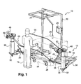
- FIG. 1 A motor vehicle bumper assembly station designated by the 10 is shown in FIG. 1.
- This mounting station 10 is composed of a frame 12 adapted to receive a removable support 14 for a bumper.
- This Mounting station 10 is intended for use by a standing operator.
- the frame 12 is constituted by an assembly of metal beams. he has a lower horizontal structure 18 on which is fixed a structure upper 20 for supporting various functional elements such as lighting 22, a control screen 24 or pneumatic tools 26.
- the frame 12 is mounted on rollers 28 which makes it possible to move it easily during a restructuring of an advanced manufacturing store.
- the frame 12 further comprises two horizontal arms fixed to the structure lower horizontal 18 by a pivot connection of vertical axis.
- the ends of the arms 30 opposed to the connection comprise rollers 32 arranged perpendicular to the direction of the arms 30 to facilitate their rotation.
- the frame 12 comprises adjustment means 34 for the angle formed between the arm 30 and lower horizontal structure 18.
- reception structures 36 of the removable support 14 for bumpers are respectively fixed on each of the two arms 30, at their opposite end to the link pivot. These reception structures 36 are constituted by uprights 36 vertical.
- each upright 36 is provided with means for removably hooking the support 14 for bumpers.
- the adjustment means 34 of the angle formed between the arms and the structure lower horizontal means of adjusting 34 the distance between the uprights 36 vertical. These means 34 for adjusting the distance between the uprights 36 allow to adapt the frame 12 to supports 14 of different widths.
- the support 14 is constituted by a central structure 38 intended to receive bumper and two lateral branches 40 for fixing the support 14 to vertical uprights 36 of the frame 12.
- the central structure 38 of the support 14 is provided with sensors (not shown) connected to a treatment device. These sensors make it possible to verify that the operations to be performed on the bumper have been correctly performed by the operator. The sensor information is then displayed on the control screen 24.
- the adjustment means 34 of the angle formed between an arm 30 and the structure lower horizontal 18 of the frame 12 are constituted by a perforated rod 34 horizontal.
- this perforated rod 34 is fixed to the structure lower horizontal 18 with a pin 42 inserted into one of the perforations, this perforation being chosen according to the desired angle.
- the second end of the perforated rod 34 is attached to the arm 30 using a pin 42 inserted in a slot 44 formed in this rod 34 perforated.
- This slot 44 which extends perpendicular to the perforated rod 34 allows compensate for the displacement of the end of the arm 30 generated by its rotation, and allows so the perforated rod 34 to keep the same direction permanently. She permits also fine adjustments of the distance between the two uprights 36.
- FIGS. 2 and 3 Two configurations of the frame 12 are shown in FIGS. 2 and 3.
- the frame receives a support 14 for bumpers of small dimensions.
- the vertical uprights 36 are therefore close and perforated rods 34 are not used over their entire length.
- the frame 12 receives a support 14 for bumpers large dimensions.
- the distance between the vertical uprights 36 is therefore greater that in FIG. 2 and the perforated rods 34 are used over their entire length, it is up to say that the pins 42 are placed in the perforations at the ends of the perforated rods 34.
- the frame 12 of the invention can be used with a fixed support 14 or with a mobile support 14.
- support 14 is movable about a horizontal axis passing through the upper ends two uprights 36 vertical.
- Each vertical upright 36 then comprises a rotary link axis horizontal for fastening a lateral branch 40 of the support 14 to an upright 36 vertical frame 12.
- the support 14 can rotate around an axis horizontal which allows the operator to access all sides of the bumper.
- each of its lateral branches 40 has a counterweight 46 which compensates for the weight of its central structure 38 and the bumper.
- the uprights 36 of the frame comprise brakes 48.
- These brakes 48 are constituted by two toothed wheels 50 secured in rotation of the support and by two racks 52 connected to the uprights 36.
- the immobilization of the support 14 is achieved by the engagement of the racks 52 in the teeth of the gear wheels 50.
- support 14 is fixed.
- the fixed support 14 used is different from the mobile support 14 of the first mode of operation: the lateral branches 40 are oriented towards the interior of the support 14.
- each upright 36 has a recess connection for fixing a branch lateral 40 of the support 14 to an upright 36 of the frame 12.
- the length of the bumper support 14 used is then greater than the distance between the two uprights 36 of the chassis. This configuration has the advantage to minimize the floor area occupied by the assembly station 10.
- the support used in this second mode of maybe a table, shaped like the bumper, attached to the chassis.
- This table may for example be molded resin.
- the frame 12 comprises a central housing intended to accommodate a supply store 54 and two lateral housing aligned with the central housing, these lateral housings being able to accommodate the Bumper sticks carried by the support.
- This configuration makes it possible to bring supplies closer to the operator.
- the frame is also designed so that the central housing comprises, on the face of the frame opposite to the support, an opening allowing the insertion of a store supply 54.
- This central accommodation makes it possible to use shops indifferently supply 54 in the form of pallets or in the form of inclined.
Landscapes
- Engineering & Computer Science (AREA)
- Manufacturing & Machinery (AREA)
- Chemical & Material Sciences (AREA)
- Combustion & Propulsion (AREA)
- Transportation (AREA)
- Mechanical Engineering (AREA)
- Automobile Manufacture Line, Endless Track Vehicle, Trailer (AREA)
- Body Structure For Vehicles (AREA)
- Warehouses Or Storage Devices (AREA)
- Vehicle Step Arrangements And Article Storage (AREA)
Abstract
Description
- un logement central destiné à accueillir un magasin d'approvisionnement,
- deux logements latéraux alignés avec le logement central aptes à accueillir les crosses d'un pare-chocs porté par le support.
- les structures d'accueil du châssis sont disposées de manière à ce que la distance les séparant est inférieure à la longueur du support,
- le logement central comporte sur la face du châssis opposée au support, une ouverture permettant l'insertion d'un magasin d'approvisionnement.
- la figure 1 est un schéma en perspective d'un poste de montage muni d'un châssis selon l'invention,
- la figure 2 est un schéma vu du dessus d'un poste de montage muni d'un châssis selon l'invention,
- la figure 3 est un schéma similaire à la figure 2 selon un autre mode de fonctionnement,
- la figure 4 est un schéma en perspective d'un poste de montage de l'invention selon un autre mode de fonctionnement.
Claims (7)
- Châssis (12) d'un poste de montage (10) de pare-chocs de véhicules automobiles, apte à recevoir un support (14) amovible pour un pare-chocs, ce support (14) comportant deux branches latérales (40) fixées de façon amovible respectivement à deux structures d'accueil (36) du châssis (12), caractérisé en ce qu'il comporte des moyens de réglage (34) de la distance entre les structures d'accueil (36) de manière à pouvoir s'adapter à des supports (14) de largeurs différentes.
- Châssis selon la revendication 1, comportant une liaison rotative d'axe horizontal pour la fixation d'une branche latérale (40) du support (14) à une structure d'accueil (36) du châssis.
- Châssis selon la revendication 1, comportant une liaison encastrement pour la fixation d'une branche latérale (40) du support (14) à une structure d'accueil (36) du châssis.
- Châssis selon l'une des revendications précédentes, dans lequel les structures d'accueil (36) du châssis sont disposées de manière à ce que la distance les séparant est inférieure à la longueur du support (14).
- Châssis selon l'une des revendications précédentes, comportant :un logement central destiné à accueillir un magasin d'approvisionnement (54),deux logements latéraux alignés avec le logement central aptes à accueillir les crosses d'un pare-chocs porté par le support.
- Châssis selon la revendication 4, dans lequel le logement central comporte, sur la face du châssis opposée au support, une ouverture permettant l'insertion d'un magasin d'approvisionnement (54).
- Poste de montage (10) de pare-chocs de véhicules automobiles caractérisé en ce qu'il comprend un châssis (12) selon l'une des revendications 1 à 6 et un support (14) amovible pour un pare-chocs.
Applications Claiming Priority (2)
| Application Number | Priority Date | Filing Date | Title |
|---|---|---|---|
| FR0311300A FR2860175B1 (fr) | 2003-09-26 | 2003-09-26 | Chassis d'un poste de montage de pare-chocs de vehicules automobiles et poste de montage de pare-chocs de vehicules automobiles |
| FR0311300 | 2003-09-26 |
Publications (2)
| Publication Number | Publication Date |
|---|---|
| EP1518783A1 true EP1518783A1 (fr) | 2005-03-30 |
| EP1518783B1 EP1518783B1 (fr) | 2007-12-05 |
Family
ID=34178960
Family Applications (1)
| Application Number | Title | Priority Date | Filing Date |
|---|---|---|---|
| EP04292259A Expired - Lifetime EP1518783B1 (fr) | 2003-09-26 | 2004-09-21 | Châssis d'un poste de montage de pare-chocs de véhicules automobiles et poste de montage de pare-chocs de véhicules automobiles |
Country Status (5)
| Country | Link |
|---|---|
| EP (1) | EP1518783B1 (fr) |
| AT (1) | ATE380143T1 (fr) |
| DE (1) | DE602004010476T2 (fr) |
| ES (1) | ES2297356T3 (fr) |
| FR (1) | FR2860175B1 (fr) |
Cited By (2)
| Publication number | Priority date | Publication date | Assignee | Title |
|---|---|---|---|---|
| WO2011061306A1 (fr) * | 2009-11-20 | 2011-05-26 | Snecma | Chariot de transport d'un module de moteur d'aeronef |
| US9309008B2 (en) | 2009-11-20 | 2016-04-12 | Snecma | Aircraft engine module handling assembly |
Citations (3)
| Publication number | Priority date | Publication date | Assignee | Title |
|---|---|---|---|---|
| US5662315A (en) * | 1996-05-06 | 1997-09-02 | Brut Manufacturing Company | Bumper holder |
| WO1997036712A1 (fr) * | 1996-04-01 | 1997-10-09 | Johnson Bryan T | Support de maintien pour pare-chocs d'automobile |
| US6409128B1 (en) * | 1999-09-03 | 2002-06-25 | Donald T. Deshler | Painting stand for vehicle parts such as bumpers |
-
2003
- 2003-09-26 FR FR0311300A patent/FR2860175B1/fr not_active Expired - Fee Related
-
2004
- 2004-09-21 AT AT04292259T patent/ATE380143T1/de not_active IP Right Cessation
- 2004-09-21 ES ES04292259T patent/ES2297356T3/es not_active Expired - Lifetime
- 2004-09-21 EP EP04292259A patent/EP1518783B1/fr not_active Expired - Lifetime
- 2004-09-21 DE DE602004010476T patent/DE602004010476T2/de not_active Expired - Lifetime
Patent Citations (3)
| Publication number | Priority date | Publication date | Assignee | Title |
|---|---|---|---|---|
| WO1997036712A1 (fr) * | 1996-04-01 | 1997-10-09 | Johnson Bryan T | Support de maintien pour pare-chocs d'automobile |
| US5662315A (en) * | 1996-05-06 | 1997-09-02 | Brut Manufacturing Company | Bumper holder |
| US6409128B1 (en) * | 1999-09-03 | 2002-06-25 | Donald T. Deshler | Painting stand for vehicle parts such as bumpers |
Cited By (6)
| Publication number | Priority date | Publication date | Assignee | Title |
|---|---|---|---|---|
| WO2011061306A1 (fr) * | 2009-11-20 | 2011-05-26 | Snecma | Chariot de transport d'un module de moteur d'aeronef |
| FR2952921A1 (fr) * | 2009-11-20 | 2011-05-27 | Snecma | Chariot de transport d'un module de moteur d'aeronef |
| CN102656089A (zh) * | 2009-11-20 | 2012-09-05 | 斯奈克玛 | 飞机发动机单元体运输托架 |
| US8833776B2 (en) | 2009-11-20 | 2014-09-16 | Snecma | Carriage for transport of an aircraft engine module |
| CN102656089B (zh) * | 2009-11-20 | 2014-10-22 | 斯奈克玛 | 飞机发动机单元体运输托架 |
| US9309008B2 (en) | 2009-11-20 | 2016-04-12 | Snecma | Aircraft engine module handling assembly |
Also Published As
| Publication number | Publication date |
|---|---|
| DE602004010476D1 (de) | 2008-01-17 |
| DE602004010476T2 (de) | 2008-12-11 |
| FR2860175A1 (fr) | 2005-04-01 |
| ES2297356T3 (es) | 2008-05-01 |
| ATE380143T1 (de) | 2007-12-15 |
| FR2860175B1 (fr) | 2006-03-10 |
| EP1518783B1 (fr) | 2007-12-05 |
Similar Documents
| Publication | Publication Date | Title |
|---|---|---|
| FR2986727A1 (fr) | Outillage pour le montage d'une lame de ressort de suspension au chassis et aux supports de roues d'un train roulant d'un vehicule automobile et pour son demontage | |
| FR2487656A1 (fr) | Siege pour poussette de bebe | |
| FR2989131A1 (fr) | Bras porteur de charge reglable, dispositif de suspension d'une charge | |
| EP1518783B1 (fr) | Châssis d'un poste de montage de pare-chocs de véhicules automobiles et poste de montage de pare-chocs de véhicules automobiles | |
| FR2834951A1 (fr) | Tablette arriere pour vehicule automobile dote d'un toit repliable | |
| FR2762565A1 (fr) | Siege a ceinture integree de securite, d'un vehicule automobile, comprenant un retracteur pour la ceinture de securite et un palpeur commandant celui-ci | |
| FR2964617A1 (fr) | Mecanisme d'essuie-vitre comprenant un systeme de blocage en position sur la structure du vehicule | |
| EP1157870B1 (fr) | Store à enrouleur à barre de tirage mobile axialement | |
| EP3888979A1 (fr) | Porte-vélo escamotable | |
| EP1816390A1 (fr) | Dispositif de fixation d'un accessoire du type audiovisuel ou informatique, en périphérie d'un support sensiblement plan | |
| EP1396383B1 (fr) | Cache-bagages pour véhicule automobile | |
| EP3587224B1 (fr) | Dispositif de fixation d'une roue de secours d'un véhicule automobile | |
| WO2013017392A1 (fr) | Pare soleil pour motocycle | |
| FR2809063A1 (fr) | Porte-velo pour vehicule automobile | |
| FR2727346A1 (fr) | Dispositif d'equilibrage des forces agissant sur un bras sollicite par une charge | |
| FR3025148A1 (fr) | Siege pour un vehicule comprenant un plancher de chargement | |
| FR3099107A1 (fr) | Planche de bord agencee pour maintenir un appareil multimedia nomade dans un vehicule et vehicule correspondant | |
| FR3012385A1 (fr) | Siege escamotable anti deversement | |
| FR2752548A1 (fr) | Dispositif formant appui-tete pour siege de vehicule automobile | |
| FR3055254A1 (fr) | Dispositif de guidage d’une vitre mobile montee dans la porte d’un vehicule, notamment automobile | |
| FR2835795A1 (fr) | Entretoise de blocage angulaire des bielles d'un bras d'essuie-glace | |
| FR3038577A1 (fr) | Ensemble de retenue d'une roue de secours a dispositif de sortie facilitant l'acces a la roue de secours. | |
| FR3056373A1 (fr) | Equipement pour maintenir un composant a l'interieur d'un boitier d'ordinateur | |
| CA1302335C (fr) | Systeme d'entrainement de chariots sur un rail et procede pour sa mise en oeuvre | |
| FR2511959A1 (fr) | Dispositif de fixation d'un enrouleur de ceinture de securite sur un siege de vehicule |
Legal Events
| Date | Code | Title | Description |
|---|---|---|---|
| PUAI | Public reference made under article 153(3) epc to a published international application that has entered the european phase |
Free format text: ORIGINAL CODE: 0009012 |
|
| AK | Designated contracting states |
Kind code of ref document: A1 Designated state(s): AT BE BG CH CY CZ DE DK EE ES FI FR GB GR HU IE IT LI LU MC NL PL PT RO SE SI SK TR |
|
| AX | Request for extension of the european patent |
Extension state: AL HR LT LV MK |
|
| 17P | Request for examination filed |
Effective date: 20050928 |
|
| AKX | Designation fees paid |
Designated state(s): AT BE BG CH CY CZ DE DK EE ES FI FR GB GR HU IE IT LI LU MC NL PL PT RO SE SI SK TR |
|
| GRAP | Despatch of communication of intention to grant a patent |
Free format text: ORIGINAL CODE: EPIDOSNIGR1 |
|
| GRAS | Grant fee paid |
Free format text: ORIGINAL CODE: EPIDOSNIGR3 |
|
| GRAA | (expected) grant |
Free format text: ORIGINAL CODE: 0009210 |
|
| AK | Designated contracting states |
Kind code of ref document: B1 Designated state(s): AT BE BG CH CY CZ DE DK EE ES FI FR GB GR HU IE IT LI LU MC NL PL PT RO SE SI SK TR |
|
| REG | Reference to a national code |
Ref country code: GB Ref legal event code: FG4D Free format text: NOT ENGLISH |
|
| REG | Reference to a national code |
Ref country code: IE Ref legal event code: FG4D Free format text: LANGUAGE OF EP DOCUMENT: FRENCH |
|
| REG | Reference to a national code |
Ref country code: CH Ref legal event code: EP |
|
| REF | Corresponds to: |
Ref document number: 602004010476 Country of ref document: DE Date of ref document: 20080117 Kind code of ref document: P |
|
| GBT | Gb: translation of ep patent filed (gb section 77(6)(a)/1977) |
Effective date: 20080312 |
|
| PG25 | Lapsed in a contracting state [announced via postgrant information from national office to epo] |
Ref country code: SE Free format text: LAPSE BECAUSE OF FAILURE TO SUBMIT A TRANSLATION OF THE DESCRIPTION OR TO PAY THE FEE WITHIN THE PRESCRIBED TIME-LIMIT Effective date: 20080305 Ref country code: NL Free format text: LAPSE BECAUSE OF FAILURE TO SUBMIT A TRANSLATION OF THE DESCRIPTION OR TO PAY THE FEE WITHIN THE PRESCRIBED TIME-LIMIT Effective date: 20071205 |
|
| REG | Reference to a national code |
Ref country code: ES Ref legal event code: FG2A Ref document number: 2297356 Country of ref document: ES Kind code of ref document: T3 |
|
| PG25 | Lapsed in a contracting state [announced via postgrant information from national office to epo] |
Ref country code: SI Free format text: LAPSE BECAUSE OF FAILURE TO SUBMIT A TRANSLATION OF THE DESCRIPTION OR TO PAY THE FEE WITHIN THE PRESCRIBED TIME-LIMIT Effective date: 20071205 Ref country code: FI Free format text: LAPSE BECAUSE OF FAILURE TO SUBMIT A TRANSLATION OF THE DESCRIPTION OR TO PAY THE FEE WITHIN THE PRESCRIBED TIME-LIMIT Effective date: 20071205 Ref country code: PL Free format text: LAPSE BECAUSE OF FAILURE TO SUBMIT A TRANSLATION OF THE DESCRIPTION OR TO PAY THE FEE WITHIN THE PRESCRIBED TIME-LIMIT Effective date: 20071205 |
|
| NLV1 | Nl: lapsed or annulled due to failure to fulfill the requirements of art. 29p and 29m of the patents act | ||
| PG25 | Lapsed in a contracting state [announced via postgrant information from national office to epo] |
Ref country code: AT Free format text: LAPSE BECAUSE OF FAILURE TO SUBMIT A TRANSLATION OF THE DESCRIPTION OR TO PAY THE FEE WITHIN THE PRESCRIBED TIME-LIMIT Effective date: 20071205 |
|
| PG25 | Lapsed in a contracting state [announced via postgrant information from national office to epo] |
Ref country code: SK Free format text: LAPSE BECAUSE OF FAILURE TO SUBMIT A TRANSLATION OF THE DESCRIPTION OR TO PAY THE FEE WITHIN THE PRESCRIBED TIME-LIMIT Effective date: 20071205 Ref country code: RO Free format text: LAPSE BECAUSE OF FAILURE TO SUBMIT A TRANSLATION OF THE DESCRIPTION OR TO PAY THE FEE WITHIN THE PRESCRIBED TIME-LIMIT Effective date: 20071205 |
|
| PG25 | Lapsed in a contracting state [announced via postgrant information from national office to epo] |
Ref country code: PT Free format text: LAPSE BECAUSE OF FAILURE TO SUBMIT A TRANSLATION OF THE DESCRIPTION OR TO PAY THE FEE WITHIN THE PRESCRIBED TIME-LIMIT Effective date: 20080505 |
|
| REG | Reference to a national code |
Ref country code: IE Ref legal event code: FD4D |
|
| PLBE | No opposition filed within time limit |
Free format text: ORIGINAL CODE: 0009261 |
|
| STAA | Information on the status of an ep patent application or granted ep patent |
Free format text: STATUS: NO OPPOSITION FILED WITHIN TIME LIMIT |
|
| PG25 | Lapsed in a contracting state [announced via postgrant information from national office to epo] |
Ref country code: DK Free format text: LAPSE BECAUSE OF FAILURE TO SUBMIT A TRANSLATION OF THE DESCRIPTION OR TO PAY THE FEE WITHIN THE PRESCRIBED TIME-LIMIT Effective date: 20071205 Ref country code: IE Free format text: LAPSE BECAUSE OF FAILURE TO SUBMIT A TRANSLATION OF THE DESCRIPTION OR TO PAY THE FEE WITHIN THE PRESCRIBED TIME-LIMIT Effective date: 20071205 |
|
| 26N | No opposition filed |
Effective date: 20080908 |
|
| PG25 | Lapsed in a contracting state [announced via postgrant information from national office to epo] |
Ref country code: GR Free format text: LAPSE BECAUSE OF FAILURE TO SUBMIT A TRANSLATION OF THE DESCRIPTION OR TO PAY THE FEE WITHIN THE PRESCRIBED TIME-LIMIT Effective date: 20080306 |
|
| PG25 | Lapsed in a contracting state [announced via postgrant information from national office to epo] |
Ref country code: MC Free format text: LAPSE BECAUSE OF NON-PAYMENT OF DUE FEES Effective date: 20080930 Ref country code: EE Free format text: LAPSE BECAUSE OF FAILURE TO SUBMIT A TRANSLATION OF THE DESCRIPTION OR TO PAY THE FEE WITHIN THE PRESCRIBED TIME-LIMIT Effective date: 20071205 Ref country code: BG Free format text: LAPSE BECAUSE OF FAILURE TO SUBMIT A TRANSLATION OF THE DESCRIPTION OR TO PAY THE FEE WITHIN THE PRESCRIBED TIME-LIMIT Effective date: 20080305 |
|
| REG | Reference to a national code |
Ref country code: CH Ref legal event code: PL |
|
| PG25 | Lapsed in a contracting state [announced via postgrant information from national office to epo] |
Ref country code: CY Free format text: LAPSE BECAUSE OF FAILURE TO SUBMIT A TRANSLATION OF THE DESCRIPTION OR TO PAY THE FEE WITHIN THE PRESCRIBED TIME-LIMIT Effective date: 20071205 |
|
| PG25 | Lapsed in a contracting state [announced via postgrant information from national office to epo] |
Ref country code: LI Free format text: LAPSE BECAUSE OF NON-PAYMENT OF DUE FEES Effective date: 20080930 Ref country code: CH Free format text: LAPSE BECAUSE OF NON-PAYMENT OF DUE FEES Effective date: 20080930 |
|
| PG25 | Lapsed in a contracting state [announced via postgrant information from national office to epo] |
Ref country code: LU Free format text: LAPSE BECAUSE OF NON-PAYMENT OF DUE FEES Effective date: 20080921 Ref country code: HU Free format text: LAPSE BECAUSE OF FAILURE TO SUBMIT A TRANSLATION OF THE DESCRIPTION OR TO PAY THE FEE WITHIN THE PRESCRIBED TIME-LIMIT Effective date: 20080606 |
|
| PG25 | Lapsed in a contracting state [announced via postgrant information from national office to epo] |
Ref country code: TR Free format text: LAPSE BECAUSE OF FAILURE TO SUBMIT A TRANSLATION OF THE DESCRIPTION OR TO PAY THE FEE WITHIN THE PRESCRIBED TIME-LIMIT Effective date: 20071205 |
|
| PGFP | Annual fee paid to national office [announced via postgrant information from national office to epo] |
Ref country code: IT Payment date: 20100922 Year of fee payment: 7 |
|
| PG25 | Lapsed in a contracting state [announced via postgrant information from national office to epo] |
Ref country code: IT Free format text: LAPSE BECAUSE OF NON-PAYMENT OF DUE FEES Effective date: 20120921 |
|
| PG25 | Lapsed in a contracting state [announced via postgrant information from national office to epo] |
Ref country code: BE Free format text: LAPSE BECAUSE OF NON-PAYMENT OF DUE FEES Effective date: 20140930 |
|
| PGFP | Annual fee paid to national office [announced via postgrant information from national office to epo] |
Ref country code: ES Payment date: 20151028 Year of fee payment: 12 Ref country code: BE Payment date: 20150929 Year of fee payment: 12 |
|
| REG | Reference to a national code |
Ref country code: FR Ref legal event code: PLFP Year of fee payment: 13 |
|
| PG25 | Lapsed in a contracting state [announced via postgrant information from national office to epo] |
Ref country code: BE Free format text: LAPSE BECAUSE OF NON-PAYMENT OF DUE FEES Effective date: 20160930 |
|
| REG | Reference to a national code |
Ref country code: FR Ref legal event code: PLFP Year of fee payment: 14 |
|
| REG | Reference to a national code |
Ref country code: BE Ref legal event code: MM Effective date: 20160930 |
|
| PG25 | Lapsed in a contracting state [announced via postgrant information from national office to epo] |
Ref country code: ES Free format text: LAPSE BECAUSE OF NON-PAYMENT OF DUE FEES Effective date: 20160922 |
|
| REG | Reference to a national code |
Ref country code: FR Ref legal event code: PLFP Year of fee payment: 15 |
|
| PGFP | Annual fee paid to national office [announced via postgrant information from national office to epo] |
Ref country code: FR Payment date: 20180926 Year of fee payment: 15 Ref country code: DE Payment date: 20180920 Year of fee payment: 15 |
|
| REG | Reference to a national code |
Ref country code: ES Ref legal event code: FD2A Effective date: 20181126 |
|
| PGFP | Annual fee paid to national office [announced via postgrant information from national office to epo] |
Ref country code: GB Payment date: 20180919 Year of fee payment: 15 Ref country code: CZ Payment date: 20180919 Year of fee payment: 15 |
|
| REG | Reference to a national code |
Ref country code: DE Ref legal event code: R119 Ref document number: 602004010476 Country of ref document: DE |
|
| PG25 | Lapsed in a contracting state [announced via postgrant information from national office to epo] |
Ref country code: CZ Free format text: LAPSE BECAUSE OF NON-PAYMENT OF DUE FEES Effective date: 20190921 |
|
| PG25 | Lapsed in a contracting state [announced via postgrant information from national office to epo] |
Ref country code: DE Free format text: LAPSE BECAUSE OF NON-PAYMENT OF DUE FEES Effective date: 20200401 |
|
| GBPC | Gb: european patent ceased through non-payment of renewal fee |
Effective date: 20190921 |
|
| PG25 | Lapsed in a contracting state [announced via postgrant information from national office to epo] |
Ref country code: FR Free format text: LAPSE BECAUSE OF NON-PAYMENT OF DUE FEES Effective date: 20190930 Ref country code: GB Free format text: LAPSE BECAUSE OF NON-PAYMENT OF DUE FEES Effective date: 20190921 |