EP1518639B1 - Dispositif pour enlever des pièces finies d'une chambre de traitement - Google Patents
Dispositif pour enlever des pièces finies d'une chambre de traitement Download PDFInfo
- Publication number
- EP1518639B1 EP1518639B1 EP04021644A EP04021644A EP1518639B1 EP 1518639 B1 EP1518639 B1 EP 1518639B1 EP 04021644 A EP04021644 A EP 04021644A EP 04021644 A EP04021644 A EP 04021644A EP 1518639 B1 EP1518639 B1 EP 1518639B1
- Authority
- EP
- European Patent Office
- Prior art keywords
- receptacle
- receiving container
- receiving
- closure element
- lid
- Prior art date
- Legal status (The legal status is an assumption and is not a legal conclusion. Google has not performed a legal analysis and makes no representation as to the accuracy of the status listed.)
- Expired - Lifetime
Links
- 238000003754 machining Methods 0.000 title claims description 5
- 238000004519 manufacturing process Methods 0.000 claims description 43
- 238000000034 method Methods 0.000 claims description 36
- 238000012546 transfer Methods 0.000 claims description 6
- 238000007599 discharging Methods 0.000 claims description 4
- 125000004122 cyclic group Chemical group 0.000 claims 1
- 238000012545 processing Methods 0.000 description 5
- 238000005259 measurement Methods 0.000 description 4
- 238000013461 design Methods 0.000 description 3
- 238000003780 insertion Methods 0.000 description 3
- 230000037431 insertion Effects 0.000 description 3
- 230000006835 compression Effects 0.000 description 2
- 238000007906 compression Methods 0.000 description 2
- 238000011109 contamination Methods 0.000 description 2
- 238000011161 development Methods 0.000 description 2
- 230000018109 developmental process Effects 0.000 description 2
- 239000000463 material Substances 0.000 description 2
- 230000001070 adhesive effect Effects 0.000 description 1
- 239000007795 chemical reaction product Substances 0.000 description 1
- 238000001816 cooling Methods 0.000 description 1
- 239000000110 cooling liquid Substances 0.000 description 1
- 230000008878 coupling Effects 0.000 description 1
- 238000010168 coupling process Methods 0.000 description 1
- 238000005859 coupling reaction Methods 0.000 description 1
- 238000013016 damping Methods 0.000 description 1
- 238000000605 extraction Methods 0.000 description 1
- 230000005484 gravity Effects 0.000 description 1
- 230000001050 lubricating effect Effects 0.000 description 1
- 239000007769 metal material Substances 0.000 description 1
- 238000012544 monitoring process Methods 0.000 description 1
Images


Classifications
-
- B—PERFORMING OPERATIONS; TRANSPORTING
- B23—MACHINE TOOLS; METAL-WORKING NOT OTHERWISE PROVIDED FOR
- B23Q—DETAILS, COMPONENTS, OR ACCESSORIES FOR MACHINE TOOLS, e.g. ARRANGEMENTS FOR COPYING OR CONTROLLING; MACHINE TOOLS IN GENERAL CHARACTERISED BY THE CONSTRUCTION OF PARTICULAR DETAILS OR COMPONENTS; COMBINATIONS OR ASSOCIATIONS OF METAL-WORKING MACHINES, NOT DIRECTED TO A PARTICULAR RESULT
- B23Q7/00—Arrangements for handling work specially combined with or arranged in, or specially adapted for use in connection with, machine tools, e.g. for conveying, loading, positioning, discharging, sorting
- B23Q7/008—Catching devices
-
- B—PERFORMING OPERATIONS; TRANSPORTING
- B23—MACHINE TOOLS; METAL-WORKING NOT OTHERWISE PROVIDED FOR
- B23Q—DETAILS, COMPONENTS, OR ACCESSORIES FOR MACHINE TOOLS, e.g. ARRANGEMENTS FOR COPYING OR CONTROLLING; MACHINE TOOLS IN GENERAL CHARACTERISED BY THE CONSTRUCTION OF PARTICULAR DETAILS OR COMPONENTS; COMBINATIONS OR ASSOCIATIONS OF METAL-WORKING MACHINES, NOT DIRECTED TO A PARTICULAR RESULT
- B23Q7/00—Arrangements for handling work specially combined with or arranged in, or specially adapted for use in connection with, machine tools, e.g. for conveying, loading, positioning, discharging, sorting
- B23Q7/08—Arrangements for handling work specially combined with or arranged in, or specially adapted for use in connection with, machine tools, e.g. for conveying, loading, positioning, discharging, sorting by means of slides or chutes
Definitions
- the invention relates to a device for discharging production parts from a process space, in particular from a process space in machine tools, which are provided for processing of production parts.
- From the DE 16 02 713 A1 is a device for taking over a workpiece in the working space of a workpiece machine and to transport the same to a lying outside the working space transfer point known.
- This device comprises a two-part receptacle, which is formed from a vessel and a closure plate.
- the vessel has a trough formed by two wall parts and is partially closed by a rear wall.
- On a side facing the male workpiece the vessel is open and can be partially closed by means of the closure plate.
- the closure plate is dimensioned such that it is in its closed position on the vessel leaves an opening into which the workpiece can dive when pivoting down the device in a removal position.
- Such a device has the disadvantage that a quick transport out of the workpieces to achieve short cycle times is not possible, since the vessel is formed open on one side even with a closed closure plate and the workpiece can fall out.
- From the JP 55112705 is a device for the removal of manufacturing parts from a process room out, which also have an open drip tray.
- An analog arrangement goes out of the DE 28 23 479 A1 out. In these open drip trays, the same risk as in the drip according to the EP 0 282 717 A1 ,
- the invention is therefore based on the object to propose a device for removing manufacturing parts from a process space, which allows a secure recording of the production part and a controlled removal from the process room to increase process reliability.
- a receptacle with an openable lid and openable closure element which is provided for receiving at least one production part and can be positioned for workpiece reception, a secure removal of the or the production parts as well as a safe emptying of the receptacle allows. Due to the design of the receptacle and very small and light parts can be safely led out of the process space, even if they are afflicted with a cooling or processing medium and / or chips or the like.
- the collecting container according to the invention can be ensured by means of the collecting container according to the invention that, independently of the travel speed for bringing the receiving container out of the process space, the at least one recorded production part is reliably led out.
- the receptacle according to the invention comprises a lid which is opened in a receiving position and a closure element which is opened in a discharge position.
- the lid of the container is opened before or during the transfer of the receptacle in the receiving position.
- the receptacle can be positioned to receive the at least one production part prepared in the process chamber in order to allow even low cycle times.
- the positioning of the receptacle or the beginning of the positioning of the receptacle in the process space is adapted to the working cycle of the machine tools and is preferably controlled by this.
- the operation of the lid for the receptacle can be done actively by an actuator or passively by a stop.
- a stop may be provided on a positioning drive for the receptacle, thereby causing an opening movement of the cover to take place simultaneously during insertion of the receptacle into the process space.
- the size and the design of the receptacle can be simplified be.
- a variety of geometry for the design of the receptacle is made possible to allow insertion of the receptacle even with very small or lean process spaces or feed paths in the process space.
- the Abtransportiser and a bottom of the receptacle are positioned in a discharge position of the receptacle to each other such that when transferring the receptacle in a discharge position on the one hand a closure lid of the Abtransportiser open and parallel to this extent a closure element on Receptacle is opened.
- a wall portion which is positioned to the cover or the support surface, designed as a scraper, so that when moving the support surface or the closure element in the emptying position ensures that the production parts are transferred to the Abtransport nie.
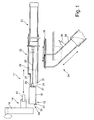
- a device 11 according to the invention is arranged in a receiving position 12 relative to a production part 13 in order to receive this production part 13 after ejection from a workpiece holder 14.
- the workpiece holder 14 is provided, for example, on a multi-spindle drive not shown in detail or in a machine tool or in a machining center.
- a plurality of workpiece holders 14 are provided on a rotating disk 16, so that several production parts can be processed simultaneously and a partial or complete processing of the production parts 13 is made possible by clockwise indexing.
- the production parts 13 form an intermediate or an end product during removal.
- the last processing step for the production part 13 has been carried out, so that this can be led out of the machine tool.
- the last step may include a measurement of the length of the components.
- a control measurement such as a length diameter or tolerance measurement of predetermined sections can take place.
- the device 11 is formed in this embodiment as a receptacle 18 which is formed depending on the size of the process space 19 for receiving one or more production parts.
- the receptacle 18 is moved horizontally via an actuator 21, so that it can be transferred from the receiving position 12 into a discharge position 22, which is shown in dashed lines.
- the actuator 21 is formed for example as a pneumatic cylinder.
- any other drives such as hydraulic, electro-hydraulic, electrical or mechanical drives or actuators, may be provided.
- the supply movement and removal movement of the receptacle 18 is performed.
- the horizontal movement illustrated in FIG. 1 it is also possible, for example, for feeding and discharging the receiving container 18 to take place obliquely from below or obliquely from above.
- a push rod 23 is arranged on the receptacle 18 via a corresponding coupling element 24.
- a cam-controlled movement or a two- or three-dimensional movement path can also be provided.
- the receptacle 18 has a lid 26, which is preferably designed as a sliding element.
- This cover 26 has an engagement surface 27 which engages a stop 28 during the transfer from the emptying position 22 into the receiving position 12.
- a further actuator is provided, which is provided in or outside of the receptacle 18, which opens the lid 26 in or immediately before reaching the receiving position 12.
- a signal can preferably be output via a sensor provided in the receptacle 18, whereafter the cover 26 is automatically transferred from its open position into a closed position.
- this can be done by a tension spring 29, as shown in Figure 2.
- the stop 28 can release the attack surface 27.
- the cover 26 automatically closes during the process from the receiving position 12 into the emptying position 22.
- the lid 26 may be provided that in the receptacle 18 a kind of trap is formed, which allows the dropping from above manufacturing part 13 enters the receptacle 18, but even in a quick and jerky method falling out through the Trap is prevented and a lid is not required.
- the travel speed between the pickup position 12 and the emptying position 22 is determined by the cycle time of the machine tool and may be less than five seconds.
- the actuation of the actuator 21 is preferably made via the same control of the machine tool, so that a vote on the cycle times of the machine tool is possible.
- FIG. 1 makes it possible for a production part 13 to be emptied after receiving a production part 13.
- a stop 31 arranged below or laterally of the receiving container 18 acts on a closure element 32, which is preferably provided on an underside of the receiving container 18.
- the closure element 32 is analogous to the lid 26 as Sliding element formed, which has an engagement surface 27 which abuts against the stop 31.
- the closure element 32 may also be provided on a lateral portion.
- This closure element 32 opens for emptying the production part 13 from the receptacle 18. This allows the manufacturing part 13 are transferred from the receptacle 18 in a Abtransport worn 34, so that the or the manufacturing parts of a collecting container, which is not shown in detail, are supplied.
- the removal unit 34 is formed according to this embodiment by a material tube, which in length and the positioning of the emptying position 22 of the receptacle 18 is adaptable.
- the removal device 34 can preferably be operated with a volume flow, so that an extraction takes place. Likewise, a removal can be made possible only by the gravity of the production parts 13.
- the removal unit 34 advantageously also has a closure element 36 to protect against contamination.
- This closure element 36 is advantageously opened simultaneously when transferring the receiving container 18 into the emptying position 22.
- the closure element 36 bears against an end face 37 of the receptacle 18 or a stop arranged in front of it and is opened by the latter during the process into the emptying position 22. This can ensure that contamination or clogging of the removal device 34 is not given.
- At least one sensor 39 may be provided, which detects a transported away manufacturing part. As a result, there may be additional control over the number of production parts transferred to a collecting container.
- both the cover 26 and the closure element 32 are preferably by a tension spring 29 from an open position independently convertible into a closed position.
- mechanical drive elements or electric motors are provided.
- external drives or actuating elements located outside of the receptacle 18 it is also possible for external drives or actuating elements located outside of the receptacle 18 to be provided in order to actuate the cover 26 and the closure element 32.
- a process section 19 facing wall portion 42 is preferably formed with a slope 43.
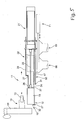
- FIG. 5 shows an alternative embodiment of the device 11 according to the invention for FIG.
- This alternative embodiment has a base module 66, which has at least one attachment portion not shown for connection to the actuator 21 and includes a guide 67 in which the receptacle 18 is movable back and forth.
- This basic module 66 simultaneously enables the arrangement and reception of a removal device 34, for example according to FIG. 1, or a removal device 34 according to FIG. 8. The latter is arranged displaceably on the basic module 66.
- the removal device 34 has a first pipe 68 for the removal of good parts and a second pipe 69 for the removal of bad parts.
- the Abtransport worn 34 is transferred via an actuator 71 in a good or bad position, so that after removal of the component 13 through the receptacle 18, the first or second pipe 68th , 69 is positioned in the emptying position 22 to the receptacle 18.
- a sorting for good and bad parts are initiated.
- the basic module 66 is provided for receiving different sizes of receptacles 18 and / or removal devices 34.
- the removal device 34 shown in FIG. 5 may also be provided with the sensors 39 for counting and monitoring the removed parts.
- FIGS. 6 and 7 show an alternative embodiment of a receptacle 18.
- the plan view of Figure 9 shows the receptacle in a closed position.
- a front side 73 of the receptacle 18 is wedge-shaped to allow reliable removal due to the narrow process space by at least the bottom of the component 13 completely engages under.
- the container 18 is formed in this embodiment with an end opening 74, wherein the right and left wall side is closed.
- the container 18 is positioned in the process space below the component 13.
- a slope or slide 76 the component 13 reaches a lower portion of the bottom or closure element 32 for removal.
- the end face 73 is formed by an opening 74, advantageously a brush strip 77 or the like may be provided, thereby allowing the component during insertion of the receptacle 18 in the process space is passed unhindered through the brush bar 77, but at a quick and jerky removal of the component is held captive within the receptacle 18.
- the closure element 32 is held in a closed position by a positive guide 78.
- This positive guide 78 comprises, for example, a left and right pressure element 79, which engages via a holder 81 on the bottom or the closure element 32.
- the pressure element 79 which is designed as a compression spring, For example, the shutter member 32 is kept in a closed state.
- the holder 81 is formed for example as a U-shaped bracket, which is fastened on an underside to the closure element 32 and is received on the left and right in a pressure chamber in which the pressure element 39 is also guided. This may be, for example, a compression spring, disc springs or other rubber-elastic damping elements that allow a certain travel and ensure a quick return movement to close the container.
- the receptacle 18 and the lid 26, the closure element 32 and the base module 66 and the removal device 34 are preferably made of plastic. Particularly stressed parts, such as guides, can be formed by metallic materials, so that these metallic guide elements are used.
- the inner wall portions of the receptacle 18 are preferably round or rounded. This allows parts to not stick in corners.
- the adhesive effect is increased by the provided with lubricating and / or cooling liquid parts.
- the inside of the closure element 32 that is, the bearing surfaces facing the interior of the receptacle 18, is formed as a rough surface in order to reduce adhesion of the parts.
- corrugated or corrugated bottom molds can be used to enable safe emptying after each working cycle or after several working cycles.
- the removal device 34 shown in FIG. 5 can also be provided with further pipelines. Alternatively to the sorting of goods and bad parts can also be removed in a processing machine differently manufactured components according to the process space and assigned to the respective basket. With a larger number of pipes 68, 69, which are provided for the removal, also a semicircular or an elongate rail can be assigned to the basic module, which extends substantially perpendicular to the drive direction of the actuator 21.
- the device for removing production parts may also be formed by a combination of a receiving container and a suction device.
- a plurality of devices for discharging production parts of a machine tool are assigned or that with a drive unit several devices in the process space in and out of the process space or any combination of the arrangement of one or more devices to one or more machine tools is trained.
Landscapes
- Engineering & Computer Science (AREA)
- Mechanical Engineering (AREA)
- Automatic Assembly (AREA)
- Auxiliary Devices For Machine Tools (AREA)
- Powder Metallurgy (AREA)
Claims (7)
- Dispositif pour évacuer des pièces finies (13) d'une chambre de traitement (19), notamment d'une chambre de traitement dans des machines-outils, qui est positionné dans la chambre de traitement (19) après l'usinage d'au moins une pièce finie à recevoir, afin de ressortir l'au moins une pièce finie de la chambre de traitement (19), comprenant un récipient de réception (18) qui est prévu pour recevoir au moins une pièce finie (13) et qui, pour recevoir l'au moins une pièce finie (13), peut être adapté au traitement cadencé des pièces finies (13),
caractérisé en ce que
le récipient de réception (18) présente un couvercle (26) et une portion ouvrable avec un élément de fermeture (32), le couvercle (26) se fermant après que la pièce finie (13) a été reçue ou pendant le retrait du récipient de réception (18) hors de la chambre de traitement (19), et l'élément de fermeture (32) étant ouvert dans une position de vidage (22) du récipient de réception (18). - Dispositif selon la revendication 1, caractérisé en ce qu'avant ou pendant le transfert du récipient de réception (18) dans la position de réception (12), le couvercle (26) du récipient de réception (18) est actionné.
- Dispositif selon la revendication 1, caractérisé en ce que le couvercle (26) du récipient de réception (18) est actionné activement par une unité de commande ou passivement par une butée (31).
- Dispositif selon la revendication 3, caractérisé en ce que l'unité de commande ou la butée (31) est prévue sur ou dans le récipient de réception (18) ou en dehors du récipient de réception (18).
- Dispositif selon la revendication 1, caractérisé en ce que l'élément de fermeture (32) est prévu latéralement ou au fond sur une portion ouvrable dans le récipient de réception (18).
- Dispositif selon l'une quelconque des revendications précédentes, caractérisé en ce que le récipient de réception (18) est positionné vers une unité d'évacuation (34) dans la position de vidage (22) et au moins une pièce finie (13) peut être acheminée à l'unité d'évacuation (34) par le biais de la portion ouvrable de l'unité d'évacuation (34).
- Dispositif selon la revendication 1, caractérisé en ce qu'au moins une portion de paroi (42) du récipient de réception (18) adjacente au couvercle (26) est réalisée sous forme de racle.
Applications Claiming Priority (2)
| Application Number | Priority Date | Filing Date | Title |
|---|---|---|---|
| DE10344497A DE10344497A1 (de) | 2003-09-24 | 2003-09-24 | Vorrichtung zum Abführen von Fertigungsteilen aus einem Prozessraum |
| DE10344497 | 2003-09-24 |
Publications (4)
| Publication Number | Publication Date |
|---|---|
| EP1518639A2 EP1518639A2 (fr) | 2005-03-30 |
| EP1518639A3 EP1518639A3 (fr) | 2006-02-15 |
| EP1518639B1 true EP1518639B1 (fr) | 2008-01-23 |
| EP1518639B8 EP1518639B8 (fr) | 2008-04-23 |
Family
ID=34177945
Family Applications (1)
| Application Number | Title | Priority Date | Filing Date |
|---|---|---|---|
| EP04021644A Expired - Lifetime EP1518639B8 (fr) | 2003-09-24 | 2004-09-10 | Dispositif pour enlever des pièces finies d'une chambre de traitement |
Country Status (2)
| Country | Link |
|---|---|
| EP (1) | EP1518639B8 (fr) |
| DE (2) | DE10344497A1 (fr) |
Families Citing this family (5)
| Publication number | Priority date | Publication date | Assignee | Title |
|---|---|---|---|---|
| JP5596851B2 (ja) * | 2011-03-28 | 2014-09-24 | シチズンホールディングス株式会社 | ワークの回収装置 |
| DE102016121028A1 (de) | 2016-11-03 | 2018-05-03 | EZU-Metallwaren GmbH & Co. KG | Auffangsystem für in einer Werkzeugmaschine bearbeitete Werkstücke, Auffangvorrichtung hierfür sowie Auffangverfahren für in einer Werkzeugmaschine bearbeitete Werkstücke |
| EP3800005B1 (fr) * | 2019-10-02 | 2023-09-20 | Mecha AG | Dispositif de dechargement de petites pièces d'une machine-outil |
| CN111774918B (zh) * | 2020-08-20 | 2021-08-24 | 湖北文理学院 | 一种棒料下料装置 |
| JP7568917B2 (ja) * | 2020-12-18 | 2024-10-17 | スター精密株式会社 | 工作機械、及び、その制御方法 |
Family Cites Families (9)
| Publication number | Priority date | Publication date | Assignee | Title |
|---|---|---|---|---|
| FR2392747A1 (fr) * | 1977-05-31 | 1978-12-29 | Ardex Sa | Dispositif recuperateur de pieces, pour tours automatiques ou analogues |
| JPS55112705A (en) * | 1979-02-26 | 1980-08-30 | Yoshida Seisakusho:Kk | Work collecting device |
| JPS6150746A (ja) * | 1984-08-16 | 1986-03-13 | Motokane Matsumoto | 自動切削加工機の加工品取り出し装置 |
| DE3704606A1 (de) * | 1987-02-13 | 1988-08-25 | Traub Ag | Verfahren und einrichtung zum ueberwachen einer programmgesteuerten werkzeugmaschine |
| DE8808183U1 (de) * | 1988-06-25 | 1988-08-18 | Masi Haller KG Metallwaren und Styropor, 7809 Simonswald | Vorrichtung zum Auffangen und Abwerfen von Werkstücken, insbesondere für einen Drehautomaten |
| JPH1110407A (ja) * | 1997-06-25 | 1999-01-19 | Okuma Mach Works Ltd | ワーク払い出し装置 |
| US5911803A (en) * | 1997-09-04 | 1999-06-15 | Miyano; Toshiharu Tom | System and method for delivering elongate workpieces to a point of use |
| US6189424B1 (en) * | 1999-06-24 | 2001-02-20 | Visteon Global Technologies, Inc. | Loader and unloader for machine tool |
| DE10023915A1 (de) * | 2000-05-17 | 2001-11-29 | Karl Goeckel | Spannvorrichtung zum Halten eines Gegenstandes durch Ansaugen desselben |
-
2003
- 2003-09-24 DE DE10344497A patent/DE10344497A1/de not_active Withdrawn
-
2004
- 2004-09-10 EP EP04021644A patent/EP1518639B8/fr not_active Expired - Lifetime
- 2004-09-10 DE DE502004006025T patent/DE502004006025D1/de not_active Expired - Lifetime
Also Published As
| Publication number | Publication date |
|---|---|
| EP1518639A2 (fr) | 2005-03-30 |
| EP1518639A3 (fr) | 2006-02-15 |
| DE502004006025D1 (de) | 2008-03-13 |
| EP1518639B8 (fr) | 2008-04-23 |
| DE10344497A1 (de) | 2005-04-28 |
Similar Documents
| Publication | Publication Date | Title |
|---|---|---|
| DE102008056246A1 (de) | Montagegerät, System und Verfahren zur Montage von in eine Öffnung eines Werkstücks einzusetzende, als Schüttgut vorliegende Bauteile | |
| DE102004055629A1 (de) | Vorrichtung und Verfahren zum aufeinanderfolgenden Entleeren von mit Artikeln gefüllten Behältern | |
| EP1518639B1 (fr) | Dispositif pour enlever des pièces finies d'une chambre de traitement | |
| DE102016121028A1 (de) | Auffangsystem für in einer Werkzeugmaschine bearbeitete Werkstücke, Auffangvorrichtung hierfür sowie Auffangverfahren für in einer Werkzeugmaschine bearbeitete Werkstücke | |
| WO2017186673A1 (fr) | Dispositif de transport à pinces de préhension | |
| EP2886283B1 (fr) | Dispositif de fabrication de pièces en matière plastique ayant des inserts dans un procédé de moulage par injection | |
| EP2939768A2 (fr) | Magasin de chargement de barres de matériau | |
| DE102021112702A1 (de) | Aufschneide-Maschine | |
| EP1607175B1 (fr) | Support pour porteur d'outil | |
| DE102007059566B3 (de) | Kassetten-Wechselvorrichtung und Verfahren zum Kassettenwechsel | |
| DE102021132899B3 (de) | Sprüheinrichtung für einen Werkstückwechsler sowie Werkstückwechsler und Verfahren zum Handhaben von plattenförmigen Werkstücken | |
| EP4408752B1 (fr) | Procédé et dispositif pour acheminer un groupe de produits de l'industrie du tabac, en tant que contenu d'emballage, jusqu'à une pièce découpée pour un emballage pour des produits de l'industrie du tabac | |
| DE102008014958B4 (de) | Vorrichtung zum Spritzen von Kunststoffteilen sowie deren Entnahme | |
| DE102020102578A1 (de) | Behälter und Verfahren zum Zuführen oder Nachlegen von stabförmigenArtikeln der Tabakindustrie | |
| DE102018210472B4 (de) | Kompaktvereinzeler | |
| DE3918236A1 (de) | Verfahren und anordnung zum ueberfuehren einer im wesentlichen horizontalen reihe von zigaretten oder aehnlichen stabfoermigen gegenstaenden | |
| DE10127109A1 (de) | Vorrichtung zur Entnahme und Vereinzelung von Beuteln aus Stapelträgern | |
| EP3249762B1 (fr) | Dispositif pour une machine de traitement de cable destine au chargement automatique et de preference au dechargement de logements de boitier de connexion comprenant des boitiers de connexion correspondants | |
| EP4377072B1 (fr) | Station de purge et procédé de purge | |
| DE102007047562A1 (de) | Handhabungsvorrichtung zum Handhaben von Schragen sowie Anordnung und Verfahren zum Entleeren von Schragen | |
| DE29713814U1 (de) | Vorrichtung zur Übergabe von einer Anzahl von Dornbruchnieten | |
| DE19850544A1 (de) | Befüll- und Verschließstation | |
| EP2161097B1 (fr) | Dispositif d'extraction d'une tige à partir d'un mandrin d'une machine rotative | |
| DE10202642B4 (de) | Ablagevorrichtung für Datenträgerkarten | |
| DE102012109065A1 (de) | Werkzeuggreifer für einen Werkzeughalter |
Legal Events
| Date | Code | Title | Description |
|---|---|---|---|
| PUAI | Public reference made under article 153(3) epc to a published international application that has entered the european phase |
Free format text: ORIGINAL CODE: 0009012 |
|
| AK | Designated contracting states |
Kind code of ref document: A2 Designated state(s): AT BE BG CH CY CZ DE DK EE ES FI FR GB GR HU IE IT LI LU MC NL PL PT RO SE SI SK TR |
|
| AX | Request for extension of the european patent |
Extension state: AL HR LT LV MK |
|
| PUAL | Search report despatched |
Free format text: ORIGINAL CODE: 0009013 |
|
| AK | Designated contracting states |
Kind code of ref document: A3 Designated state(s): AT BE BG CH CY CZ DE DK EE ES FI FR GB GR HU IE IT LI LU MC NL PL PT RO SE SI SK TR |
|
| AX | Request for extension of the european patent |
Extension state: AL HR LT LV MK |
|
| 17P | Request for examination filed |
Effective date: 20060816 |
|
| AKX | Designation fees paid |
Designated state(s): CH DE FR IT LI |
|
| 17Q | First examination report despatched |
Effective date: 20061110 |
|
| GRAP | Despatch of communication of intention to grant a patent |
Free format text: ORIGINAL CODE: EPIDOSNIGR1 |
|
| GRAS | Grant fee paid |
Free format text: ORIGINAL CODE: EPIDOSNIGR3 |
|
| GRAA | (expected) grant |
Free format text: ORIGINAL CODE: 0009210 |
|
| AK | Designated contracting states |
Kind code of ref document: B1 Designated state(s): CH DE FR IT LI |
|
| REG | Reference to a national code |
Ref country code: CH Ref legal event code: EP |
|
| REF | Corresponds to: |
Ref document number: 502004006025 Country of ref document: DE Date of ref document: 20080313 Kind code of ref document: P |
|
| RAP2 | Party data changed (patent owner data changed or rights of a patent transferred) |
Owner name: HUBER, STEPHAN |
|
| RIN2 | Information on inventor provided after grant (corrected) |
Inventor name: HUBER, STEPHAN |
|
| REG | Reference to a national code |
Ref country code: CH Ref legal event code: NV Representative=s name: E. BLUM & CO. AG PATENT- UND MARKENANWAELTE VSP |
|
| RAP2 | Party data changed (patent owner data changed or rights of a patent transferred) |
Owner name: HUBER, STEPHAN |
|
| RIN2 | Information on inventor provided after grant (corrected) |
Inventor name: HUBER, STEPHAN |
|
| ET | Fr: translation filed | ||
| PLBE | No opposition filed within time limit |
Free format text: ORIGINAL CODE: 0009261 |
|
| STAA | Information on the status of an ep patent application or granted ep patent |
Free format text: STATUS: NO OPPOSITION FILED WITHIN TIME LIMIT |
|
| 26N | No opposition filed |
Effective date: 20081024 |
|
| PGFP | Annual fee paid to national office [announced via postgrant information from national office to epo] |
Ref country code: CH Payment date: 20110913 Year of fee payment: 8 |
|
| PGFP | Annual fee paid to national office [announced via postgrant information from national office to epo] |
Ref country code: FR Payment date: 20110922 Year of fee payment: 8 |
|
| PGFP | Annual fee paid to national office [announced via postgrant information from national office to epo] |
Ref country code: IT Payment date: 20110916 Year of fee payment: 8 |
|
| REG | Reference to a national code |
Ref country code: CH Ref legal event code: PL |
|
| REG | Reference to a national code |
Ref country code: FR Ref legal event code: ST Effective date: 20130531 |
|
| PG25 | Lapsed in a contracting state [announced via postgrant information from national office to epo] |
Ref country code: LI Free format text: LAPSE BECAUSE OF NON-PAYMENT OF DUE FEES Effective date: 20120930 Ref country code: CH Free format text: LAPSE BECAUSE OF NON-PAYMENT OF DUE FEES Effective date: 20120930 |
|
| PG25 | Lapsed in a contracting state [announced via postgrant information from national office to epo] |
Ref country code: IT Free format text: LAPSE BECAUSE OF NON-PAYMENT OF DUE FEES Effective date: 20120910 Ref country code: FR Free format text: LAPSE BECAUSE OF NON-PAYMENT OF DUE FEES Effective date: 20121001 |
|
| PGFP | Annual fee paid to national office [announced via postgrant information from national office to epo] |
Ref country code: DE Payment date: 20131218 Year of fee payment: 10 |
|
| REG | Reference to a national code |
Ref country code: DE Ref legal event code: R119 Ref document number: 502004006025 Country of ref document: DE |
|
| PG25 | Lapsed in a contracting state [announced via postgrant information from national office to epo] |
Ref country code: DE Free format text: LAPSE BECAUSE OF NON-PAYMENT OF DUE FEES Effective date: 20150401 |