EP1518626A2 - Tieflochbohrer und Einspannvorrichtung - Google Patents
Tieflochbohrer und Einspannvorrichtung Download PDFInfo
- Publication number
- EP1518626A2 EP1518626A2 EP04022849A EP04022849A EP1518626A2 EP 1518626 A2 EP1518626 A2 EP 1518626A2 EP 04022849 A EP04022849 A EP 04022849A EP 04022849 A EP04022849 A EP 04022849A EP 1518626 A2 EP1518626 A2 EP 1518626A2
- Authority
- EP
- European Patent Office
- Prior art keywords
- deep hole
- clamping device
- hole drill
- collet
- drill
- Prior art date
- Legal status (The legal status is an assumption and is not a legal conclusion. Google has not performed a legal analysis and makes no representation as to the accuracy of the status listed.)
- Withdrawn
Links
Images


Classifications
-
- B—PERFORMING OPERATIONS; TRANSPORTING
- B23—MACHINE TOOLS; METAL-WORKING NOT OTHERWISE PROVIDED FOR
- B23B—TURNING; BORING
- B23B51/00—Tools for drilling machines
- B23B51/04—Drills for trepanning
- B23B51/0486—Drills for trepanning with lubricating or cooling equipment
-
- B—PERFORMING OPERATIONS; TRANSPORTING
- B23—MACHINE TOOLS; METAL-WORKING NOT OTHERWISE PROVIDED FOR
- B23B—TURNING; BORING
- B23B31/00—Chucks; Expansion mandrels; Adaptations thereof for remote control
- B23B31/02—Chucks
- B23B31/10—Chucks characterised by the retaining or gripping devices or their immediate operating means
- B23B31/12—Chucks with simultaneously-acting jaws, whether or not also individually adjustable
- B23B31/20—Longitudinally-split sleeves, e.g. collet chucks
- B23B31/201—Characterized by features relating primarily to remote control of the gripping means
- B23B31/2012—Threaded cam actuator
- B23B31/20125—Axially fixed cam, moving jaws
-
- B—PERFORMING OPERATIONS; TRANSPORTING
- B23—MACHINE TOOLS; METAL-WORKING NOT OTHERWISE PROVIDED FOR
- B23B—TURNING; BORING
- B23B2251/00—Details of tools for drilling machines
- B23B2251/24—Overall form of drilling tools
- B23B2251/247—Drilling tools having a working portion at both ends of the shank
-
- B—PERFORMING OPERATIONS; TRANSPORTING
- B23—MACHINE TOOLS; METAL-WORKING NOT OTHERWISE PROVIDED FOR
- B23B—TURNING; BORING
- B23B2260/00—Details of constructional elements
- B23B2260/126—Seals
-
- B—PERFORMING OPERATIONS; TRANSPORTING
- B23—MACHINE TOOLS; METAL-WORKING NOT OTHERWISE PROVIDED FOR
- B23B—TURNING; BORING
- B23B51/00—Tools for drilling machines
- B23B51/06—Drills with lubricating or cooling equipment
- B23B51/063—Deep hole drills, e.g. ejector drills
- B23B51/066—Gun drills
Definitions
- the invention relates to a deep hole drill with associated Chuck.
- Deep hole drills are preferred for drilling boreholes used, the borehole diameter to the borehole depth in a ratio z. B. lies between 1:10 and 1: 100. Deep hole drills have a corresponding geometric Design of the tool shank very good cutting properties of the drill head and very good sliding properties of the tool shank on the wall of the borehole on.
- Excellent cutting properties of the deep hole drill be through the use of carbide drill heads achieved.
- An optimization of the sliding properties of the Deep hole drill in the borehole is done by reducing the Friction surface between tool shank and bore wall.
- the reduction of the friction surface is in a known manner either by attaching axially running narrow executed guide rails on the outer diameter of the Tool shank as a spacer between tool shank and bore wall or by reducing the outer diameter of the tool shank against the outer diameter realized the drill head.
- U1 is a deep hole drill shown. He has a drill head, a tool shank and a clamping sleeve. Drilling head and tool shank like also tool shank and clamping sleeve are each about a Solder joint connected together. To the defined Removal of the cut at the hole chip is in Drill head and tool shank an asymmetric V-shaped Axialnut provided. The leadership of the coolant takes place in the drill head and tool shank by an axial extending cooling channel. Good cutting properties are achieved by the use of a carbide drill head. Low friction and thus good sliding properties between Tool shank and bore wall are replaced by a Tool shank realized whose outer diameter made smaller than the outer diameter of the drill head is.
- a disadvantage of such a design of a deep hole drill is in relation to the task to be performed - Drilling a deep hole - comparatively high Complexity of the tool structure, which made three perfect various components - drill head, tool shank and clamping sleeve - consists.
- the manufacturing costs of the deep hole drill by the need for a suitable connection technology for the connection of the different ones Components additionally increased.
- An additional constructive Design of the individual components with regard to realizing connection and an additional manufacturing step - Soldering - increase product and production complexity of the deep hole drill unnecessary.
- Another disadvantage of the deep hole drill of DE 297 16 377 U1 is the limited setting of the overhang length of the Call a deep hole drill. Since the overhang length of the Tieflochbohrers only by axial displacement of the Clamping sleeve in the clamping device of the machine tools can be realized, represents the limited length of the Clamping sleeve a limitation for a highly variable Adjustment of the overhang length of the deep hole drill.
- the invention is therefore based on the object, a Deep hole drill according to the preamble of claim 1 and to develop a clamping device such that the Deep hole drill a simple structure as possible in the With regard to cost-effective production and in its projection length is as far as possible adjustable.
- the object of the invention is achieved by a deep hole drill with the features of claim 1 and a Clamping device with the features of claim 6 solved.
- the inventive, preferably single-lipped Deep hole drill is by integration of the drill head, the Tool shank and the clamping sleeve in a component realized.
- the deep hole drill according to the invention exists from a cylindrical tool shank, in which a asymmetrical V-shaped axial groove in full length is executed.
- the tool shank goes by its two Each ends in a continuous transition into a drill head over.
- the expression of two drill heads respectively at the two Ends of the monocular deep hole drill according to the invention doubles the life of the tool on average.
- the simple geometry of the single-lipped invention Deep Hole Drill also simplifies the repair effort of the tool, since a regrinding of such Deep hole drill in case of wear simpler - easier Devices and tools as well as higher automation for regrinding possible - can be realized.
- An adjustment of the projecting length of the invention single lip deep hole drill over as wide as possible Range is achieved by a clamping device according to the invention realized, in which the deep hole drill on a Any point of his tool shank in one Through hole of a collet chuck is held. In this way is an axial Displacement of the deep hole drill in the invention Clamping device possible.
- This axial freedom of movement of the deep hole drill in the jig is by appropriate geometric configuration of supports other components of the saving device.
- the single-lip deep hole drill according to the invention has in the Area of its two drill heads a larger outside diameter than in the area of the tool shank. To this Way, the friction surface between deep hole drills and Bore wall reduces and thus the sliding property of the increased according to the invention single-lip deep hole drill.
- single lip deep hole drill will be especially for the two drill bits used a carbide material.
- the area of the tool shank be made of steel instead of carbide.
- Deep hole drill is a running in the axial direction Cooling channel provided.
- a major problem with tensioners in particular from deep hole drills is the purposeful guidance of the Coolant over the clamping device in the cooling channels the deep hole drill and, consequently, a reliable Sealing of the clamping device against leakage of Coolant at undesirable locations - for example the collet - the clamping device.
- a first Embodiment of the clamping device according to the invention in the through hole of a union nut through which the inventive einlippige deep hole drill from the first embodiment of the clamping device according to the invention is led out, installed a shut-off, this is the entire clamping device according to the invention sealing off coolant flowing out.
- a Second embodiment of the clamping device according to the invention is the obturator in the first. or second Inner bore of a shaft in which the invention single lip deep hole drills within the invention Clamping device is guided, installed to escape of coolant from the clamping device according to the invention to avoid.
- the obturator in his Center has a recess whose cross-sectional profile the profile of the monocular deep hole drill according to the invention corresponds, the obturator takes over the additional Task of centered leadership and radial Attachment of the monocular deep hole drill according to the invention.
- the jig is over the shaft in the Clamping device of a machine tool clamped and therefore indicates a to the clamping device of the machine tool adapted outer profile on.
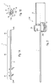
- the single-lip deep hole drill 1 is in the side view in Fig. 1A and in the plan view in FIG. 1B.
- the deep hole drill 1 consists of a first drill head 2, on which a tool shank 3 connects, which in turn in a second drill head 4 passes.
- the deep hole drill 1 consists of a cylindrical basic profile, into which a V-shaped axially directed axial groove 5 for targeted Removal of cut at the bore chip is incorporated.
- the tool shank 3 has, in a first region 41 containing the first drill head 2 and in a second region 42 containing the second drill head 4, a diameter D 1 which is slightly larger than the diameter D 2 between the first and third regions 41 and 42 third area 43 is. Due to the slight difference between the two diameters D 1 and D 2 , a largely continuous transition between the first and third regions 41 and 43 or between the second and third regions 42 and 43 is possible. Due to the slightly smaller diameter D 2 of the third region 43, the deep hole drill 1 is only in contact with the bore wall via the comparatively small lateral surfaces of the first and second regions 41 and 42. The friction surfaces between the deep hole drill 1 and the bore wall are thus reduced, which leads to an improvement in the sliding properties.
- first and second drill head 2 and 4 several separated by radially directed edges Open areas 11A, 11B, 11C and 11D.
- the first and second drill head 2 and 4 each consists of a Main cutting edge 6, which is at the transition between the V-shaped Axialnut 5 and the free surface 11A in the area between the Outer jacket surface 7 and arranged eccentrically Peak 8 runs.
- the secondary cutting edge 9 also runs at the transition between the V-shaped axial groove 5 and the Free surface 11A in the area between the tip 8 and the Center 10 of the deep hole drill 1.
- Geometrie myself done with the main cutting edge 6 a much more extensive Spanrough than with the minor cutting edge 9.
- a cooling channel 12 for example, a kidney-shaped Profile, from the first to the second drill head 2 and 4 guided.
- the deep hole drill 1 can completely from a Hard metal material to be made.
- each of the first and second drill heads 2 and 4 contain a carbide material used while in the third area, which is of no relevance to the Cutting process, a common steel used come.
- FIGs. 2 and 3 is a first embodiment of a Clamping device 13A according to the invention with a clamped single-lipped deep hole drill according to the invention 1 shown.
- the deep hole drill 1 is guided centered in a rotationally symmetrical collet 14 and fixed axially and radially.
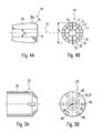
- the rotationally symmetrical collet 14 has, according to FIG. 4A, for this purpose a centrally arranged through hole 16, in which the deep hole drill 1 is kept taut.
- the projecting length of the deep hole drill 1 from the jig 13A is determined by the axial positioning of the deep hole drill in the collet 14. Since the diameter D 3 of the through hole 16 corresponds to the diameter D 2 of the first and second drill heads 2 and 4 of the deep hole drill 1, the deep hole drill 1 without problems in first through hole 16 of the collet 14 in and out.
- the collet according to FIG. 4B comprises a plurality of segments 17 extending in the axial direction, which are separated from one another by slots 18 likewise extending in the axial direction.
- the directed to the rotation axis 15 clamping force, which acting on the collet 14 is generated by the Collet 14 with its first conically shaped Part body 19 in a likewise comically shaped and in the first end face 32 centrally arranged first Inner bore 20 of a rotationally symmetrical shaft 21st is added.
- the inner diameter of the conically shaped first inner bore 20 of the shaft 21 slightly smaller as the outer diameter of the conically shaped first Part body 19 of the collet 14 is designed acts at Inserting the collet 14 in the shaft 21 from the shaft 21st on the collet 14 a clamping force to a radial directed compression of the collet 14 leads.
- the snap connections 22 between collet 14 and Union nut 23 takes place between the conically shaped second part of the body 25 of the collet 14 and an intermediate first and second body part 19 and 25 located annular groove 26 and a likewise conically shaped Inner bore portion 27 in an inner bore 26 of the Union nut 23 and one to the conically shaped Inner bore 27 subsequent web 28 in the Inner bore 26 of the union nut 23.
- the conical shaped second part of the body 25 of the collet 14 has the same diameter and the same profile height as the conical inner bore portion 27 in the Inner bore 26 of the union nut 23. Analogous corresponds to the diameter of the annular groove 26 of the Collet 14 the inner diameter of the web 28 in the Inner bore 26 of the union nut 23. In this way arises upon engagement of the web 28 of the union nut 23rd in the annular groove 26 of the collet 14 a positive snap connection between the collet 14 and the union nut 23.
- the component assembly of collet 14 and union nut 23 is connected via a screw 24 between Union nut 22 and shaft 21 for axial fixation of Collet 14 in the first inner bore 20 of the shank 21 attached.
- the shaft 21 of the clamping device 13A points in Continuation of conical and centric arranged first inner bore 20 also a centrally arranged second inner bore 33, the up to the second end face 34 of the shaft 21 extends.
- These serves on the one hand as a supply channel for coolant from the Clamping the machine tool to the cooling channel 12 of the Deep hole drill 1 and on the other hand as necessary Storage space for the deep hole drill 1, if small set overhang length of the deep hole drill 1 with a larger part of its drill length from the first through hole 16 in the first conically shaped part body 19th the collet 14 protrudes.
- the union nut 32 has in the center of its end wall 35th a through hole 36 through which the deep hole drill 1 led out of the jig 13A becomes.
- a shut-off 37A As a seal against unwanted leakage of Coolant from the chuck 13A is in one first embodiment of the clamping device according to the invention 13A in the through hole 36 a shut-off 37A let in.
- a shut-off element 37B is designed with a cylindrical partial body 46 whose outside diameter D 5 is slightly larger than the diameter D 6 of the second internal bore 33 of the shaft 21 , and a subsequent to the cylindrical part of body 46 flange part body 47, the outer diameter D 7 is slightly larger than the smallest diameter D 8 of the conical first inner bore 20 of the shaft 21 is designed in the first and second inner bore 20 and 33 of the shaft 21 by means Press fit sealing inserted.
- a sealing ring 49 is inserted in an annular groove 48 in the flange-shaped part body 47 of the obturator 37B. The interference fit of the obturator 37B in the first and second inner bores 20 and 33 of the shaft 21 and the sealing ring 49 provide a seal of the second embodiment of the clamping device 13B according to the invention against escaping coolant.
- the two shut-off valves 37A and 37B of the first and Second embodiment of the clamping device according to the invention 13A and 13B show the removal of the deep hole drill 1 from the chuck 13A and 13B in FIG its center a recess 38, whose cross-sectional profile the profile of the deep hole drill 1 corresponds. On this way will provide additional centering and radial Attachment of the deep hole drill 1 in the jig 13A or 13B through the obturator 37A or 37B completed.
- shut-off device 37B respectively flush with the two ends 44 and 45 of the single-lipped Tieflochbohrers 1 added to the deep hole drill 1 to the first and second drill head 2 and 4 during transport too protect.
Landscapes
- Engineering & Computer Science (AREA)
- Mechanical Engineering (AREA)
- Drilling And Boring (AREA)
- Drilling Tools (AREA)
Abstract
Description
- Fig. 1A, 1B
- eine Seitenansicht und eine Draufsicht eines erfindungsgemäßen einlippigen Tieflochbohrers;
- Fig. 2
- eine Seitenansicht einer ersten Ausführungsform der erfindungsgemäßen Einspannvorrichtung mit einem eingespannten erfindungsgemäßen einlippigen Tieflochbohrers im Halbschnitt;
- Fig. 3
- eine Längsschnittdarstellung einer ersten Ausführungsform der erfindungsgemäßen Einspannvorrichtung mit einem eingespannten erfindungsgemäßen einlippigen Tieflochbohrer ;
- Fig. 4A, 4B
- eine Längsschnittdarstellung und eine Draufsicht einer Spannzange;
- Fig. 5A, 5B
- eine Seitenansicht und eine Draufsicht einer Überwurfmutter;
- Fig. 6A,
- eine Seitenansicht einer zweiten Ausführungsform der erfindungsgemäßen Einspannvorrichtung mit einem eingespannten erfindungsgemäßen einlippigen Tieflochbohrers im Halbschnitt;
- Fig. 6B
- eine Längsschnittdarstellung eines Ausschnitts der zweiten Ausführungsform der erfindungsgemäßen Einspannvorrichtung mit einem eingespannten erfindungsgemäßen einlippigen Tieflochbohrer und
- Fig. 6C
- eine Draufsicht eines Absperrorgans der zweiten Ausführungsform der erfindungsgemäßen Einspannvorrichtung.
Claims (22)
- Tieflochbohrer (1) mit einem eine Axialnut (5) enthaltenden Werkzeugschaft (3) und einem ersten Bohrkopf (2), der an einem ersten an den Werkzeugschaft (3) angrenzenden Ende (44) des Tieflochbohrers (1) angebracht ist,
dadurch gekennzeichnet, daß der Werkzeugschaft (3) sich vom ersten Bohrerkopf (2) bis zu einem zweiten Bohrerkopf (4) erstreckt, der an einem zweiten Ende (45) des Tieflochbohrers (1) angebracht ist. - Tieflochbohrer nach Anspruch 1,
dadurch gekennzeichnet, daß im Innern des Werkzeugschafts (3) und im ersten und zweiten Bohrkopf (2, 4) zumindest ein in achsparalleler Richtung vom ersten bis zum zweiten Bohrerkopf (2, 4) verlaufender Kühlkanal (12) vorgesehen ist. - Tieflochbohrer nach Anspruch 1 oder 2,
dadurch gekennzeichnet, daß der Werkzeugschaft (3) in einem an den ersten und zweiten Bohrerkopf (2, 4) jeweils angrenzender ersten und zweiten Bereich (41, 42) jeweils einen geringfügig größeren Durchmesser D1 aufweist als der Durchmesser D2 in einem zwischen dem ersten und zweiten Bereich (41, 42) befindlichen dritten Bereich (43). - Tieflochbohrer nach einem der Ansprüche 1 bis 3,
dadurch gekennzeichnet, daß der einlippige Tieflochbohrer (1) aus Hartmetall besteht. - Tieflochbohrer nach Anspruch 3,
dadurch gekennzeichnet, daß der erste und zweite Bohrerkopf (2, 4) und der jeweils angrenzende erste und zweite Bereich (41, 42) des Werkzeugschaftes (3) aus Hartmetall und der dritte Bereich (43) des Werkzeugschafts (3) einem anderen Metall, insbesondere aus Stahl, besteht. - Einspannvorrichtung (13A; 13B) zur zentrischen Führung und axialen und radialen Befestigung eines Tieflochbohrers (1) nach einem der Ansprüche 1 bis 5 mit einer den Tieflochbohrer (1) aufnehmenden Spannzange (14), einem die Spannzange (14) in seiner ersten Innenbohrung (20) gespannt haltenden Schaft (21), einer die Spannzange (14) in der ersten Innenbohrung (20) des Schaftes (21) in axialer Richtung fixierenden Überwurfmutter (23) und einem Absperrorgan (37A; 37B),
wobei der Tieflochbohrer (1) zur Einstellung seiner Auskraglänge an einer beliebigen Stelle des Werkzeugschaftes (3) in der Einspannvorrichtung (13A; 13B) einspannbar ist. - Einspannvorrichtung nach Anspruch 6,
dadurch gekennzeichnet, daß die Spannzange (14) zur Aufnahme des Tieflochbohrers (1) eine Durchgangsbohrung (16) aufweist, deren Durchmesser D3 geringfügig größer als der Durchmesser des lippenförmigen Tieflochbohrers (1) ist. - Einspannvorrichtung nach Anspruch 6 oder 7,
dadurch gekennzeichnet, daß die Überwurfmutter (23) eine axial verlaufende Innenbohrung (26) mit einem Innengewinde (31) und an ihrer Stirnwand (35) eine sich zentral an die Innenbohrung (26) anschließende Durchgangsbohrung (36) zur zentrischen Führung des einlippigen Tieflochbohrers (1) ausweist. - Einspannvorrichtung nach einem der Ansprüche 6 bis 8,
dadurch gekennzeichnet, daß die Spannzange (14) ein rotationssyymmetrisches Profil aufweist, dessen Außendurchmesser in einem ersten und zweiten Teilkörper (19, 25), die durch eine ringförmige Nut (26) voneinander getrennt sind, in Richtung des jeweiligen Endes der Spannzange (14) konisch verläuft. - Einspannvorrichtung nach Anspruch 9,
dadurch gekennzeichnet, daß die Spannzange (14) mehrere durch axial verlaufende Schlitze (18) getrennte Segmente (17) umfaßt. - Einspannvorrichtung nach Anspruch 9 oder 10,
dadurch gekennzeichnet, daß die Spannzange (14) bei Einwirkung einer äußeren, zur Rotationsachse (15) der Spannzange (14) gerichteten Spannkraft hinsichtlich ihres Außendurchmessers D4 und des Durchmessers D3 ihrer Durchgangsbohrung (16) federnd zusammengespannt ist. - Einspannvorrichtung nach einem der Ansprüche 9 bis 11,
dadurch gekennzeichnet, daß zwischen Spannzange (14) und Überwurfmutter (23) eine Schnappverbindung (22) besteht, indem ein Formschuß zwischen dem konisch verlaufenden zweiten Teilkörper (25) und der ringförmigen Nut (26) der Spannzange (14) und einem zwischen Innengewinde (31) und Stirnwand (35) der Überwurfmutter (23) angebrachten Steg (28) sowie einem konisch verlaufenden Innenbohrungsbereich (27), dessen Innendurchmesser dem Außendurchmesser des konisch verlaufenden ersten Teilkörper (19) der Spannzange (14) entspricht, gebildet ist. - Einspannvorrichtung nach einem der Ansprüche 9 bis 12,
dadurch gekennzeichnet, daß der Schaft (21) an einer ersten Stirnfläche (32) eine zentrisch angeordnete und konisch verlaufende erste Innenbohrung (20) zur Aufnahme des ersten Teilkörpers (19) der Spannzange (14) aufweist, deren Innendurchmesser geringfügig kleiner als der Außendurchmesser des ersten Teilkörpers (19) der Spannzange (14) im nicht-gespannten Zustand ist. - Einspannvorrichtung nach Anspruch 13,
dadurch gekennzeichnet, daß der Schaft (21) zur Zuführung von Kühlmittel und zur axialen Verschiebung des einlippigen Tieflochbohrers (1) in der Einspannvorrichtung (13A; 13B) an einer zweiten Stirnfläche (34) eine zweite Innenbohrung (33) aufweist, die sich axial an die erste Innenbohrung (20) anschließt. - Einspannvorrichtung nach Anspruch 13 oder 14,
dadurch gekennzeichnet, daß der Schaft (21) auf seiner Außenmantelfläche (29) in der Nähe der ersten Stirnfläche (32) ein Außengewinde (30) aufweist, das mit dem Innengewinde (31) der Überwurfmutter (23) eine Schraubverbindung (24) bildet. - Einspannvorrichtung nach einem der Ansprüche 13 bis 15,
dadurch gekennzeichnet, daß der Schaft (21) ein Profil aufweist, das passend zur Spannvorrichtung einer Werkzeugmaschine ausgelegt ist. - Einspannvorrichtung nach einem der Ansprüche 6 bis 16,
dadurch gekennzeichnet, daß das Absperrorgan (37A) einen Zwischenraum zwischen der Bohrungswand der Durchgangsbohrung (36) der Überwurfmutter (23) und dem einlippigen Tieflochbohrer (1) dichtend verschließt. - Einspannvorrichtung nach Anspruch 14,
dadurch gekennzeichnet, daß das Absperrorgan (37B) einen Zwischenraum zwischen der Bohrungswand der ersten und zweiten Innenbohrung (20, 33) des Schafts (13B) und dem einlippigen Tieflochbohrer (1) dichtend verschließt. - Einspannvorrichtung nach Anspruch 18,
dadurch gekennzeichnet, daß das Absperrorgan (37B) einen zylindrischen Teilkörper (46) mit einem Außendurchmesser D5, der geringfügig größer als der Innendurchmesser D6 der zweiten Innenbohrung (33) des Schafts (21) ist, und einen an den zylindrischen Teilkörper (46) anschließenden flanschförmigen Teilkörper (47) mit einem Außendurchmesser D7, der geringfügig größer als der kleinste Durchmesser D8 des konisch verlaufenden ersten Innenbohrung (20) des Schafts (21) ist, aufweist. - Einspannvorrichtung nach Anspruch 19,
dadurch gekennzeichnet, daß das Absperrorgan (37B) in einer ringförmigen Nut (48) im flanschförmigen Teilkörper (47) einen Spannring (49) aufweist. - Einspannvorrichtung nach Anspruch 17 oder 18,
dadurch gekennzeichnet, daß das Absperrorgan (37A; 37B) zur zentrischen Führung des einlippigen Tieflochbohrers (1) eine Ausnehmung (38) aufweist, deren Querschnittsprofil dem Profil des einlippigen Tieflochbohrers (1) entspricht. - Einspannvorrichtung nach Anspruch 17 oder 18,
dadurch gekennzeichnet, daß das Absperrorgan (37A; 37B) aus einem Kunststoffmaterial besteht.
Applications Claiming Priority (4)
| Application Number | Priority Date | Filing Date | Title |
|---|---|---|---|
| DE10344620 | 2003-09-25 | ||
| DE10344620A DE10344620B4 (de) | 2003-09-25 | 2003-09-25 | Bohrwerkzeug und Spannhülse |
| DE10353324 | 2003-11-14 | ||
| DE10353324A DE10353324B3 (de) | 2003-09-25 | 2003-11-14 | Tieflochbohrer und Einspannvorrichtung |
Publications (2)
| Publication Number | Publication Date |
|---|---|
| EP1518626A2 true EP1518626A2 (de) | 2005-03-30 |
| EP1518626A3 EP1518626A3 (de) | 2005-04-06 |
Family
ID=34195770
Family Applications (1)
| Application Number | Title | Priority Date | Filing Date |
|---|---|---|---|
| EP04022849A Withdrawn EP1518626A3 (de) | 2003-09-25 | 2004-09-24 | Tieflochbohrer und Einspannvorrichtung |
Country Status (1)
| Country | Link |
|---|---|
| EP (1) | EP1518626A3 (de) |
Cited By (2)
| Publication number | Priority date | Publication date | Assignee | Title |
|---|---|---|---|---|
| WO2016008471A1 (de) * | 2014-07-16 | 2016-01-21 | Botek Präzisionsbohrtechnik Gmbh | Verfahren zum neubestücken eines einlippenbohrers und einlippenbohrer |
| CN113995468A (zh) * | 2022-01-04 | 2022-02-01 | 极限人工智能有限公司 | 夹持机构、骨钻装置及手术机器人 |
Family Cites Families (3)
| Publication number | Priority date | Publication date | Assignee | Title |
|---|---|---|---|---|
| US1379994A (en) * | 1918-05-04 | 1921-05-31 | Joseph T Ryerson & Son | Method of making drills or the like |
| GB1349033A (en) * | 1971-03-22 | 1974-03-27 | English Electric Co Ltd | Drills |
| DE3309860A1 (de) * | 1983-02-08 | 1984-08-09 | Fa. Gottlieb Gühring, 7470 Albstadt | Bohrwerkzeug |
-
2004
- 2004-09-24 EP EP04022849A patent/EP1518626A3/de not_active Withdrawn
Cited By (2)
| Publication number | Priority date | Publication date | Assignee | Title |
|---|---|---|---|---|
| WO2016008471A1 (de) * | 2014-07-16 | 2016-01-21 | Botek Präzisionsbohrtechnik Gmbh | Verfahren zum neubestücken eines einlippenbohrers und einlippenbohrer |
| CN113995468A (zh) * | 2022-01-04 | 2022-02-01 | 极限人工智能有限公司 | 夹持机构、骨钻装置及手术机器人 |
Also Published As
| Publication number | Publication date |
|---|---|
| EP1518626A3 (de) | 2005-04-06 |
Similar Documents
| Publication | Publication Date | Title |
|---|---|---|
| EP2934801B1 (de) | Werkzeughalter und zerspanwerkzeug mit dämpfungssystem | |
| EP1529585B1 (de) | Dehnspanneinrichtung | |
| EP2999565B1 (de) | Werkzeugaufnahme | |
| EP1584389B1 (de) | Dehnspanneinrichtung | |
| WO2007003248A1 (de) | Maschinenwerkzeug | |
| EP1407848B1 (de) | Gewindewerkzeug mit Kühlmittelzufuhr | |
| DE102008044996A1 (de) | Werkzeughaltervorrichtung | |
| WO1998007538A1 (de) | Dehnspannfutter | |
| DE202004005321U1 (de) | Hydraulik Dehnspannfutter | |
| EP0749795B1 (de) | Bohrwerkzeug | |
| EP1536905B1 (de) | Bohrwerkzeug mit wechselschneidplatten sowie wechselschneidplatten für ein solches bohrwerkzeug | |
| DE10144241A1 (de) | Bohrer | |
| EP1654084B1 (de) | Bohrwerkzeug | |
| DE102009015278A1 (de) | Einlippen-Tieflochbohrer | |
| EP0214927B1 (de) | Spannfutter für Bohr- und Meisselwerkzeuge | |
| DE19541163A1 (de) | Bohrwerkzeug, insbesondere zur Bearbeitung von Gestein | |
| DE2025006A1 (de) | Werkzeughalter mit radial ver stellbarem Werkzeug | |
| DE102004008166A1 (de) | Werkzeug zur spanenden Bearbeitung von Präzisionsbohrungen | |
| DE10353324B3 (de) | Tieflochbohrer und Einspannvorrichtung | |
| DE112006003063B4 (de) | Spannvorrichtung | |
| EP4417348A1 (de) | Einlippenbohrer mit auswechselbaren führungsleisten | |
| DE10351327B4 (de) | Bohrwerkzeug | |
| EP3791980B1 (de) | Spanneinrichtung mit kühlmittelzufuhr | |
| DE202019002010U1 (de) | Tiefbohrwerkzeug 2-schneidig | |
| EP1301305A1 (de) | Vorrichtung zum erzeugen von tieflochbohrungen in werkstücken mit konvexer oberfläche |
Legal Events
| Date | Code | Title | Description |
|---|---|---|---|
| PUAI | Public reference made under article 153(3) epc to a published international application that has entered the european phase |
Free format text: ORIGINAL CODE: 0009012 |
|
| PUAL | Search report despatched |
Free format text: ORIGINAL CODE: 0009013 |
|
| AK | Designated contracting states |
Kind code of ref document: A2 Designated state(s): AT BE BG CH CY CZ DE DK EE ES FI FR GB GR HU IE IT LI LU MC NL PL PT RO SE SI SK TR |
|
| AX | Request for extension of the european patent |
Extension state: AL HR LT LV MK |
|
| AK | Designated contracting states |
Kind code of ref document: A3 Designated state(s): AT BE BG CH CY CZ DE DK EE ES FI FR GB GR HU IE IT LI LU MC NL PL PT RO SE SI SK TR |
|
| AX | Request for extension of the european patent |
Extension state: AL HR LT LV MK |
|
| 17P | Request for examination filed |
Effective date: 20050808 |
|
| AKX | Designation fees paid |
Designated state(s): DE FR GB IT |
|
| 17Q | First examination report despatched |
Effective date: 20060208 |
|
| STAA | Information on the status of an ep patent application or granted ep patent |
Free format text: STATUS: THE APPLICATION IS DEEMED TO BE WITHDRAWN |
|
| 18D | Application deemed to be withdrawn |
Effective date: 20070104 |