EP1518604B1 - Microstructure device for storing small amounts of liquid and method for collecting liquid stored in this device - Google Patents
Microstructure device for storing small amounts of liquid and method for collecting liquid stored in this device Download PDFInfo
- Publication number
- EP1518604B1 EP1518604B1 EP04021864.6A EP04021864A EP1518604B1 EP 1518604 B1 EP1518604 B1 EP 1518604B1 EP 04021864 A EP04021864 A EP 04021864A EP 1518604 B1 EP1518604 B1 EP 1518604B1
- Authority
- EP
- European Patent Office
- Prior art keywords
- cavity
- blocking element
- carrier
- liquid
- force
- Prior art date
- Legal status (The legal status is an assumption and is not a legal conclusion. Google has not performed a legal analysis and makes no representation as to the accuracy of the status listed.)
- Expired - Lifetime
Links
Images


Classifications
-
- F—MECHANICAL ENGINEERING; LIGHTING; HEATING; WEAPONS; BLASTING
- F16—ENGINEERING ELEMENTS AND UNITS; GENERAL MEASURES FOR PRODUCING AND MAINTAINING EFFECTIVE FUNCTIONING OF MACHINES OR INSTALLATIONS; THERMAL INSULATION IN GENERAL
- F16K—VALVES; TAPS; COCKS; ACTUATING-FLOATS; DEVICES FOR VENTING OR AERATING
- F16K99/00—Subject matter not provided for in other groups of this subclass
- F16K99/0001—Microvalves
- F16K99/0003—Constructional types of microvalves; Details of the cutting-off member
- F16K99/0017—Capillary or surface tension valves, e.g. using electro-wetting or electro-capillarity effects
-
- B—PERFORMING OPERATIONS; TRANSPORTING
- B01—PHYSICAL OR CHEMICAL PROCESSES OR APPARATUS IN GENERAL
- B01L—CHEMICAL OR PHYSICAL LABORATORY APPARATUS FOR GENERAL USE
- B01L3/00—Containers or dishes for laboratory use, e.g. laboratory glassware; Droppers
- B01L3/50—Containers for the purpose of retaining a material to be analysed, e.g. test tubes
- B01L3/502—Containers for the purpose of retaining a material to be analysed, e.g. test tubes with fluid transport, e.g. in multi-compartment structures
- B01L3/5027—Containers for the purpose of retaining a material to be analysed, e.g. test tubes with fluid transport, e.g. in multi-compartment structures by integrated microfluidic structures, i.e. dimensions of channels and chambers are such that surface tension forces are important, e.g. lab-on-a-chip
- B01L3/502738—Containers for the purpose of retaining a material to be analysed, e.g. test tubes with fluid transport, e.g. in multi-compartment structures by integrated microfluidic structures, i.e. dimensions of channels and chambers are such that surface tension forces are important, e.g. lab-on-a-chip characterised by integrated valves
-
- F—MECHANICAL ENGINEERING; LIGHTING; HEATING; WEAPONS; BLASTING
- F16—ENGINEERING ELEMENTS AND UNITS; GENERAL MEASURES FOR PRODUCING AND MAINTAINING EFFECTIVE FUNCTIONING OF MACHINES OR INSTALLATIONS; THERMAL INSULATION IN GENERAL
- F16K—VALVES; TAPS; COCKS; ACTUATING-FLOATS; DEVICES FOR VENTING OR AERATING
- F16K99/00—Subject matter not provided for in other groups of this subclass
- F16K99/0001—Microvalves
- F16K99/0003—Constructional types of microvalves; Details of the cutting-off member
- F16K99/003—Valves for single use only
-
- F—MECHANICAL ENGINEERING; LIGHTING; HEATING; WEAPONS; BLASTING
- F16—ENGINEERING ELEMENTS AND UNITS; GENERAL MEASURES FOR PRODUCING AND MAINTAINING EFFECTIVE FUNCTIONING OF MACHINES OR INSTALLATIONS; THERMAL INSULATION IN GENERAL
- F16K—VALVES; TAPS; COCKS; ACTUATING-FLOATS; DEVICES FOR VENTING OR AERATING
- F16K99/00—Subject matter not provided for in other groups of this subclass
- F16K99/0001—Microvalves
- F16K99/0034—Operating means specially adapted for microvalves
-
- B—PERFORMING OPERATIONS; TRANSPORTING
- B01—PHYSICAL OR CHEMICAL PROCESSES OR APPARATUS IN GENERAL
- B01L—CHEMICAL OR PHYSICAL LABORATORY APPARATUS FOR GENERAL USE
- B01L2200/00—Solutions for specific problems relating to chemical or physical laboratory apparatus
- B01L2200/16—Reagents, handling or storing thereof
-
- B—PERFORMING OPERATIONS; TRANSPORTING
- B01—PHYSICAL OR CHEMICAL PROCESSES OR APPARATUS IN GENERAL
- B01L—CHEMICAL OR PHYSICAL LABORATORY APPARATUS FOR GENERAL USE
- B01L2300/00—Additional constructional details
- B01L2300/04—Closures and closing means
- B01L2300/041—Connecting closures to device or container
- B01L2300/044—Connecting closures to device or container pierceable, e.g. films, membranes
-
- B—PERFORMING OPERATIONS; TRANSPORTING
- B01—PHYSICAL OR CHEMICAL PROCESSES OR APPARATUS IN GENERAL
- B01L—CHEMICAL OR PHYSICAL LABORATORY APPARATUS FOR GENERAL USE
- B01L2300/00—Additional constructional details
- B01L2300/04—Closures and closing means
- B01L2300/046—Function or devices integrated in the closure
- B01L2300/047—Additional chamber, reservoir
-
- B—PERFORMING OPERATIONS; TRANSPORTING
- B01—PHYSICAL OR CHEMICAL PROCESSES OR APPARATUS IN GENERAL
- B01L—CHEMICAL OR PHYSICAL LABORATORY APPARATUS FOR GENERAL USE
- B01L2300/00—Additional constructional details
- B01L2300/06—Auxiliary integrated devices, integrated components
- B01L2300/0672—Integrated piercing tool
-
- B—PERFORMING OPERATIONS; TRANSPORTING
- B01—PHYSICAL OR CHEMICAL PROCESSES OR APPARATUS IN GENERAL
- B01L—CHEMICAL OR PHYSICAL LABORATORY APPARATUS FOR GENERAL USE
- B01L2400/00—Moving or stopping fluids
- B01L2400/06—Valves, specific forms thereof
- B01L2400/0633—Valves, specific forms thereof with moving parts
- B01L2400/0638—Valves, specific forms thereof with moving parts membrane valves, flap valves
-
- B—PERFORMING OPERATIONS; TRANSPORTING
- B01—PHYSICAL OR CHEMICAL PROCESSES OR APPARATUS IN GENERAL
- B01L—CHEMICAL OR PHYSICAL LABORATORY APPARATUS FOR GENERAL USE
- B01L2400/00—Moving or stopping fluids
- B01L2400/06—Valves, specific forms thereof
- B01L2400/0633—Valves, specific forms thereof with moving parts
- B01L2400/065—Valves, specific forms thereof with moving parts sliding valves
-
- B—PERFORMING OPERATIONS; TRANSPORTING
- B01—PHYSICAL OR CHEMICAL PROCESSES OR APPARATUS IN GENERAL
- B01L—CHEMICAL OR PHYSICAL LABORATORY APPARATUS FOR GENERAL USE
- B01L3/00—Containers or dishes for laboratory use, e.g. laboratory glassware; Droppers
- B01L3/50—Containers for the purpose of retaining a material to be analysed, e.g. test tubes
- B01L3/502—Containers for the purpose of retaining a material to be analysed, e.g. test tubes with fluid transport, e.g. in multi-compartment structures
- B01L3/5025—Containers for the purpose of retaining a material to be analysed, e.g. test tubes with fluid transport, e.g. in multi-compartment structures for parallel transport of multiple samples
-
- B—PERFORMING OPERATIONS; TRANSPORTING
- B01—PHYSICAL OR CHEMICAL PROCESSES OR APPARATUS IN GENERAL
- B01L—CHEMICAL OR PHYSICAL LABORATORY APPARATUS FOR GENERAL USE
- B01L3/00—Containers or dishes for laboratory use, e.g. laboratory glassware; Droppers
- B01L3/50—Containers for the purpose of retaining a material to be analysed, e.g. test tubes
- B01L3/508—Rigid containers without fluid transport within
- B01L3/5085—Rigid containers without fluid transport within for multiple samples, e.g. microtitration plates
-
- B—PERFORMING OPERATIONS; TRANSPORTING
- B01—PHYSICAL OR CHEMICAL PROCESSES OR APPARATUS IN GENERAL
- B01L—CHEMICAL OR PHYSICAL LABORATORY APPARATUS FOR GENERAL USE
- B01L3/00—Containers or dishes for laboratory use, e.g. laboratory glassware; Droppers
- B01L3/52—Containers specially adapted for storing or dispensing a reagent
- B01L3/523—Containers specially adapted for storing or dispensing a reagent with means for closing or opening
-
- Y—GENERAL TAGGING OF NEW TECHNOLOGICAL DEVELOPMENTS; GENERAL TAGGING OF CROSS-SECTIONAL TECHNOLOGIES SPANNING OVER SEVERAL SECTIONS OF THE IPC; TECHNICAL SUBJECTS COVERED BY FORMER USPC CROSS-REFERENCE ART COLLECTIONS [XRACs] AND DIGESTS
- Y10—TECHNICAL SUBJECTS COVERED BY FORMER USPC
- Y10T—TECHNICAL SUBJECTS COVERED BY FORMER US CLASSIFICATION
- Y10T436/00—Chemistry: analytical and immunological testing
- Y10T436/25—Chemistry: analytical and immunological testing including sample preparation
- Y10T436/2575—Volumetric liquid transfer
Definitions
- the present invention relates to a microstructured device for removably storing small quantities of liquid and a method for removing the liquid stored in this device.
- Microstructured devices are known from the prior art, which have a plate-shaped carrier, in which one-sided recesses are introduced. These recesses are connected via channels with removal chambers, via which a liquid can be removed from the device. The recess is also connected via an inlet channel in connection with an inlet chamber, via which a sample or a rinsing liquid can be introduced into the device. The sample is then removed due to transportation forces e.g. transported on the basis of capillary forces or compressive forces to the recess and passes from there via the removal channel to the removal opening. In the initially open recess so-called containers are used. These containers are plastic containers in which e.g. Reagent fluids are introduced.
- the container is opened so that the liquid contained in the container can escape from the container to mix with the supplied via the inlet channel into the recess liquid.
- the known from the prior art containers are standardized and they can be used in various carriers of microstructured devices.
- the carriers usually have a plurality of recesses, in which then various containers can be used with often different reagent fluids.
- the disadvantage of using containers for microstructured devices for removably storing Liquids is that the design of the device is strongly dictated by the shape of the container.
- the containers make it necessary that in the carrier to the container adapted recesses are provided.
- the recesses can therefore not be designed individually for each carrier, which could, for example, lead to a higher packing density of the liquids to be stored.
- Another disadvantage is that initially a relatively large amount of effort is made to bring the liquids in the container to then use the container as such in the carrier. This could also be simplified by storing the liquids directly in the carrier.
- a disadvantage of the document US Pat. No. 6,495,373 B1 disclosed device is that after a loss of the minimum force the There is a risk that the blocking element comes into a position in which it closes the currently released opening. This should be prevented to allow unhindered leakage of liquid from the first section.
- the invention is therefore based on the object to propose a microstructured device for removably storing small amounts of liquid, in which a closure of the opening of the first portion is prevented by the blocking element after elimination of the minimum force.
- This object is achieved by a microstructured device according to claim 1.
- Such a microstructured device may be used for a method according to claim 22.
- a microstructured device for removably storing small quantities of liquid in this case comprises a carrier, wherein in the carrier a cavity is provided with at least a first portion for storing the small amount of liquid.
- the first portion of the cavity is formed in the carrier as a recess.
- This first portion is closed with a cover element and a blocking element and is also advantageously limited by lateral walls formed by the carrier.
- the device according to the invention has a means for transmitting a force from the cover element to the blocking element. By means of this force is a cohesive connection between the blocking element and the carrier destructible or the blocking element itself destructible, so that the amount of liquid from the first portion of the cavity can be removed.
- the amount of liquid is thus not stored in a device according to the invention as in some prior art devices in a special container. Rather, it will the amount of liquid stored directly in the device in a cavity bounded on the one hand by the cover element and the blocking element and lateral walls, which are formed by the carrier.
- the carrier is in one piece. This means that the first cavity is formed in a one-piece carrier.
- a carrier made of several parts or a microstructured device in which the first cavity is not part of the carrier or is not formed in the carrier a compact and simple construction is achieved by the integral nature of the carrier. This construction has particular advantages in the production of the microstructured device.
- the blocking element and the carrier are integrally connected to each other.
- connection between the carrier and the blocking element or the blocking element itself has a predetermined breaking point at which a destruction of the blocking element or the bond between the blocking element and the carrier is easily possible.
- the blocking element is displaceable relative to the carrier into a release position in which the liquid can be removed from the first cavity.
- the cover element according to the invention may be a membrane, a foil or a (micro) structured plate.
- the lid member may be connected to the carrier by lamination, sealing or gluing. It is also possible that the cover element is metallized.
- the cover element of a device according to the invention can be designed such that when the force is exerted to destroy the connection between the blocking element and the carrier or to destroy the blocking element, the cover element itself is indestructible.
- a device according to the invention may be arranged to comprise elements for holding the cover element, with which the minimum force is exerted the lid member can be held in a deflected position. This makes it possible, even after elimination of the minimum (external) force to keep the cover member in the deflected position and thus also to maintain the pressure within the first portion of the cavity upright.
- the cover element of a device according to the invention is designed so that when exerting the minimum force to destroy the connection between the blocking element and the carrier or to destroy the blocking element, the cover element is destructible at least at a predetermined breaking point.
- the predetermined breaking point in the cover element can thereby encompass a region of the cover element that is smaller than a region enclosed by the predetermined breaking point between the support and the blocking element. This makes it possible for that Cover element, or the region of the cover element bordered by the predetermined breaking point from the cover element can be pushed through an opening released from the blocking element.
- a device can comprise a means for destroying the cover element with which the cover element can be destroyed when the minimum force is exerted.
- the first portion of the cavity may be vented, thereby facilitating the escape of the liquid from the first portion of the cavity.
- a device comprises elements for holding the locking element, with which, after the application of the minimum force, the blocking element can be held in a deflected position in order to prevent re-closing of the opening released from the blocking element by the blocking element. If the opening released by the blocking element is permanently open, the liquid stored in the first section of the cavity can escape from the first section even after the minimal force has been eliminated.
- the blocking element has a latching nose, which engages in the deflected position of the blocking element on a projection or the like of the carrier.
- the power transmission means comprises a plunger attached to the locking member.
- the plunger which is provided as a means for transmitting power to a device according to the invention, is not arranged in the middle of the cavity between the cover element and the blocking element, but closer to one of the walls of the first Section of the cavity arranged.
- the force then exerted on the plunger thus does not attack in the center of the locking element.
- the blocking element is preferably destroyed in the area or the connection between the blocking element and the carrier is destroyed in the region in which the plunger is arranged.
- the predetermined breaking point between the blocking element and the carrier can enclose the fastening region of the tappet on the blocking element with the exception of a so-called hinge region.
- the blocking element is thus mounted so to speak articulated on the carrier.
- the locking element mounted in an articulated manner on the support is then fixed in the open position to the support.
- the hinge region is advantageously the region in which the plunger has the greatest possible distance from a wall of the first section of the cavity of the carrier. Opposite this hinge area can then be provided as an element for holding the locking element, the locking lug on the locking element.
- a device according to the invention may comprise a mandrel facing the blocking element on the side of the blocking element facing away from the first section of the cavity.
- the blocking element By a movement of the blocking element due to the action of force in the direction of the tip of this mandrel then the blocking element can be destroyed, so that the liquid from the first cavity or the first portion of the cavity can be removed.
- the first portion of the cavity may be cylindrical. It is also possible that the first portion, in order to facilitate removal from the mold, is frusto-conical.
- a second cavity adjoins the first portion of the cavity, which is separated from the first portion by the blocking element. At least the second cavity advantageously but also the cavity and the first portion of the cavity have walls that are wetted by the liquid.
- the second portion of the cavity or the second cavity may according to the invention have a removal opening.
- the removal opening may be provided in a device according to the invention in a wall of the second portion of the cavity or a wall of the second cavity and indeed in a region which abuts the predetermined breaking point between the carrier and the blocking element as directly as possible. This is intended to ensure that the liquid emerging from the first section of the cavity can reach the removal opening in the second section or in the second cavity as simply as possible.
- the removal opening may be followed by a channel.
- a capillary force enhancing means may be provided in the second portion of the cavity or in the second cavity and / or in the channel, which is connected downstream of the removal opening.
- the capillary force enhancing means serves to accelerate or allow the transport of the liquid into the channel or through the removal opening.
- the capillary force enhancing agent may be Microstructure elements, such as trenches, steles, columns or the like, or to act a fleece insert. It is also possible that the microstructure elements combined with a nonwoven insert form the capillary force enhancing agent.
- In the second portion of the cavity or in the second cavity can also open an inlet channel.
- At least one wall of the second section may be reset at least in sections relative to at least one adjacent wall of the first section.
- This recessed portion may be formed ringnutartig.
- the device may comprise means for destroying the cover element.
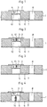
- FIGS. 1 to 16 shown embodiments for microstructured devices have great similarities, therefore, corresponding components are provided with the same reference numerals.
- FIG. 1 shown in section embodiment has an advantageous plate-shaped carrier 1, are introduced into the two opposite sides of each other recesses, which are separated from each other by a blocking element 3.
- the opening of a recess is closed by a cover element 2, whereby a first cavity 4 is formed between the cover element 2, the blocking element 3 and the lateral walls of the recess.
- This first cavity 4 is completely filled with a small amount of liquid. It is also possible that the first cavity 4 is only partially filled with the amount of liquid and contains a small gas bubble.
- the other recess is closed with a film 6, which is applied to the surface of the carrier 1, in which the recess is provided. Characterized a second cavity 5 is formed, which is bounded by the blocking element 3 of the film 6 and the lateral walls of the recesses.
- the carrier 1 also has a through hole 8, which is also closed on one side by the film 6. This through hole forms a removal chamber, which is connected via a removal channel 7 with the second cavity 5.
- the blocking element 3 has a circumferential predetermined breaking point 10, which is formed by a dilution of material on the second cavity 5 facing side.
- the stored in the first cavity 4 small amount of liquid can be removed from the first cavity 4 as follows.
- the cover element By a force acting on the cover element 2, the cover element is pressed in the direction of the amount of liquid. Since the amount of liquid is essentially incompressible, the force acts which is exerted on the cover element 2, transmitted to the locking element 3.
- This force causes as in Fig. 13 is shown, the middle part of the locking element along the circumferential predetermined breaking point 10 is broken out of the remaining blocking element 3 and so a connection between the first cavity 4 and the second cavity 5 is formed. Due to transport forces, these are usually compressive forces, the gravitational force or capillary forces, the liquid is then transported from the first cavity 4 into the second cavity 5, the channel 7 into the removal chamber 8.
- a reagent in liquid or solid form or a sample can be introduced, with which the originally stored in the first cavity amount of liquid is reacted or mixed.
- FIG. 2 illustrated embodiment differs from the in Fig. 1 illustrated embodiment in that the first cavity 4 is not completely filled with the amount of liquid. Rather, a gas-filled space remains between the liquid level and the lid member 2. Thus, the force acting on the lid member 2 for releasing the amount of liquid can still be transmitted to the locking element 10, a plunger is provided between the cover member 2 and the locking element 3, which is integrally connected to the central part of the locking element.
- the in Fig. 3 illustrated embodiment a blocking element, which has no predetermined breaking point 10.
- a mandrel 13 is fixed, which with his Tip is directed to the blocking element 3. If the cover element 2 is now pressed by a force in the direction of the blocking element 3, the mandrel 13 pierces with its tip into the blocking element 3 in order to remove the blocking effect of the blocking element 3.
- the liquid stored in the first cavity 4 can then penetrate into the second cavity 5 through the opening created in the blocking element by means of the mandrel 13.
- Fig. 4 is one of the Fig. 3 described similar embodiment in which, however, the first cavity 4 is completely filled with the amount of liquid, while on the film 6 a projecting towards the locking element 3 mandrel 14 is mounted, which causes the destruction of the blocking element 3 to release the amount of liquid.
- the blocking element 3 is deflected in the direction of the mandrel 14 via the amount of liquid in the first cavity 4, which points into the blocking element with its tip in order to destroy it. So then the amount of liquid from the first cavity 4 can penetrate into the second cavity 5.
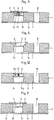
- FIG. 5 illustrated embodiment of a microstructured device is similar to that in Fig. 2 illustrated device formed. Unlike the in Fig. 2 illustrated embodiment, the embodiment in Fig. 5 in the cover element 2 a circumferential predetermined breaking point 11. As soon as the central region of the cover element is pressed down by a force, breaks the predetermined breaking point 11 and the plunger 12 presses on the middle part of the locking element 3, which eventually breaks up along the predetermined breaking point 10.
- the liquid which is stored in the first cavity 4, can enter the second cavity 5, wherein at the same time the first cavity 4 via the opening in the cover element 2 is ventilated.
- the inflowing air facilitates the outflow of the amount of liquid from the first cavity 4 into the second cavity 5.
- Fig. 5a is a variant of in Fig. 5 illustrated embodiment illustrated.
- the predetermined breaking point in the blocking element 10 encompasses an approximately circular region which completely surrounds the plunger 12.
- the predetermined breaking point 11 in the cover element 2 includes a circular area, on the underside of the plunger 12 abuts.
- the region enclosed by the predetermined breaking point 11 in the cover element 2 has a significantly smaller diameter than the region of the blocking element bordered by the predetermined breaking point 10. This has the consequence that when applying the minimum force, which is sufficient in this case, to destroy the predetermined breaking points 10, 11 in the cover element 2 and in the blocking element 3, so that the broken areas with the plunger 12 down into the second cavity 5 can be pressed.
- V in the variant of the device according to the Fig. 5a in the removal channel 7 and in a region of the second cavity 5 before the removal channel a V meneinlage 21 is provided.
- This V subjecteinlage causes an increased capillary force, which allows accelerated transport of the liquid entering the second cavity 5 through the removal channel 8.
- This in Fig. 6 illustrated embodiment of a microstructured device substantially corresponds to in Fig. 1 but different from those in Fig. 1 shown device in Fig. 6 illustrated device has no cylindrically shaped first cavity.
- the first cavity of the in Fig. 6 illustrated embodiment runs rather conically toward the locking element 3 and is thus formed substantially frusto-conical.
- the embodiment according to Fig. 7 essentially corresponds to the embodiment according to Fig. 1 However, it additionally has an inlet channel 9, which opens into the second cavity 5. Via this inlet channel 9, a second liquid can be guided into the second cavity 5, which mixes after the destruction of the blocking element 3 with the amount of liquid from the first cavity 4.
- the supplied liquid, as well as the amount of liquid in the first cavity 4, may be a sample, a reagent liquid or a rinsing liquid.
- This in Fig. 8 embodiment shown also has a first cavity 4 and a second cavity 5, wherein the device according to Fig. 8 manufactured differently than the according to Fig. 1 to 7 ,
- the carrier of the embodiment according to Fig. 8 namely, has a blind-hole-like recess which is introduced on one side into the carrier and which is subdivided into a first cavity 4 and a second cavity 5 by a blocking element 3 glued between the lateral walls. From the recess of the opposite side of the carrier channels 9, 7 are guided from the outside of the carrier to the second cavity 5, which open into the second cavity 5.
- One channel forms an inlet channel 9, while the other channel forms a withdrawal channel 7 forms.
- the glued or shrunk in between the first cavity 4 and the second cavity 5, pressed or shrunk locking element 3 has a designed in the known manner predetermined breaking point 10, on which the locking element 3 can be destroyed.
- the first cavity 4 is completely filled with a liquid amount, so that a force acting on the lid member 2 causes destruction of the locking member 3, whereby the amount of liquid in the first cavity 4 can enter the second cavity 5.
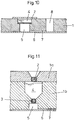
- FIGS. 9 and 14 show an embodiment which is provided with special means for the destruction of the cover element 2.
- the means for destruction are formed by a projecting into the first cavity 4 in a wedge-shaped projection 15 of the lateral wall of the first cavity 4.
- This projection forms a tip, which rests against the cover element 2. If now the cover element 2 is pressed down by the action of force, the tip of the projection 15 presses into the cover element 2 and destroys it.
- the first cavity 4 to vent the first cavity 4 in a release of the liquid contained in the first cavity 4 by destruction of the locking element 3, which facilitates the escape of the liquid from the second cavity 5.
- the first cavity has a cross-sectionally circular cross-section.
- Fig. 15 On the other hand, a cross-section of a similar device is shown, which is circular sector-like. This has the advantage that in a device having a plurality of such first cavities, as it is for example in Fig. 16 is shown, a plurality of first cavities can be compactly arranged one inside the other.
- Fig. 15 shows, moreover, another alternative means of destroying the Cover element 2, which is formed by a wedge 16 which is inserted in a recess of the lateral wall of the first chamber 4, but otherwise similar to the projection 15 according to FIG Fig. 14 destruction of the cover member 2 has a force effect.
- top view of a device shows that a device advantageously has a plurality of first cavities 4 and the blocking element 3 connected thereto.
- the second cavity (not shown) arranged below the first cavity 4 is connected to an inlet chamber 17 via an inlet channel, not shown, and to a removal chamber 8 via a withdrawal channel.
- the inlet chambers 17 can also be interconnected.
- Fig. 10 an embodiment of a microstructured device is shown, which has in carrier 1 a through hole with a shoulder.
- the through-hole above the heel has a diameter which is larger than below the heel.
- a blocking element 3 forming membrane is placed, which has an outer diameter corresponding to the inner diameter of the through hole.
- the through hole is divided into two separate parts, namely the first cavity and the second cavity 5, wherein the first cavity 4 is closed with the lid member 2 and the second cavity with the film 6.
- the device has a channel 7 designed in the known manner or a removal chamber 8 configured in the known manner.
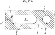
- FIGS. 17 to 17b illustrated embodiment of the invention has a cavity 4 and a second Cavity 5, which are substantially oval in cross section.
- the blocking element 3 is arranged between the two cavities 4, 5, the blocking element 3 is arranged.
- This blocking element 3 is integrally connected to the carrier 1.
- the blocking element 3 is integrally connected to a plunger 12 which is inserted in a first end region of the blocking element 3 between a cover element 2, with which the cavity 4 is closed at the top, and the blocking element 3.
- a predetermined breaking point 10 is provided between the blocking element 3 and the carrier 1, which extends from this end region along the lateral wall of the cavities 4, 5 to the opposite end region, wherein the opposite second end region is not provided with a predetermined breaking point is.
- the blocking element tears off the carrier 1 along the predetermined breaking point.
- the blocking element 3 is then connected to the carrier 1 only more via the second end region. This second end region thus forms a hinge region, on which the blocking element is pivotally mounted.
- a shoulder is formed in the first end region of the locking element 3. This shoulder cooperates with a detent 20 on the first end portion of the detent member 3 as a member for holding the detent member in a deflected position after the minimum force has acted on the lid member 2.
- the locking lug 20 engages by the breaking out and deflection of the locking element 3 down behind the paragraph in the wall of the second cavity 5 a. In this deflected position, the liquid can then flow out of the cavity 4 into the second cavity 5, even after the minimal force no longer acts on the lid element 2.
- V On the bottom of the second cavity 5 a V meneinlage 21 is provided in a central region and the end region. This V meneinlage causes an increased capillary force to transport the liquid entering the second cavity 5 through a removal channel 7 to the removal chamber 8.
- the carrier 1a, 1b of the device according to Fig. 11 is made in two parts and has a plate-shaped upper part 1a and a plate-shaped lower part 1b.
- the upper part has a conical recess, which is followed by a cylindrical bore.
- a preferably slightly elastic ball is sealingly inserted, which forms the cover element 2 of the device.
- the lower part 1b of the carrier which is mounted on the underside of the upper part 1a, has, with the recesses of the upper part 1a and the cover element 2 aligned, a first cylindrical portion, a conical portion and a second cylindrical portion, to which an advantage of the underside introduced cylindrical recess connects.
- a ball is sealingly inserted as a locking element 3, which separates the first cylindrical portion and the conical portion of the introduced from the bottom of the lower part 1b recess.
- the first cylindrical portion and the conical portion thus form the first with a liquid almost completely filled cavity 4.
- a film 6 is applied, whereby the second cavity is formed from the introduced from the bottom cylindrical recess.
- the diameter of the first cavity may be, for example, 1 to 3 mm, preferably 1.5 mm. The same applies to the second cavity.
- the blocking element 3 and the cover element 2 can have a diameter of 0.5 to 0.7 mm.
- the diameter of the first cavity of one of the embodiments according to Fig. 1 to 10 may be 2 to 8 mm, but preferably 2 to 5 mm.
- the height can be 1 to 7 mm and the volume between 10 to 100 mm 3 .
- the carrier 1 and the blocking element 3 may be made of polystyrene or polycarbonate.
- Fig. 12 illustrated embodiment, in contrast to the other embodiments, only one cavity, which has a first portion 4a, a second portion 5a.
- the cavity is variably divisible into the first section 4a and the second section 5a.
- the separation takes place via a blocking element which is displaceably mounted between the lateral walls of the first section.
- This blocking element is connected via a plunger 12 with a likewise displaceably mounted in the first portion 4a lid member 2.
- Die Sperretti 2 und 4 Sind mit dem Deckel 2 sky.
- the first portion 4a facing portion of the second portion 5a of the cavity moreover, the lateral wall of the cavity ringartigartig reset.
- the Fig. 12 shown device can be operated as follows. First, the component formed from the blocking element 3, the plunger 12 and the cover element 2 becomes as far as possible from the pulled out the first portion 4a, that the lid member 2 protrudes from the first portion 4a. By means of a gap which thereby arises between the cover element 2 and the upper end of the first section 4a of the cavity, the liquid can then be introduced into the cavity 4a. In order to then store the liquid in the first section 4a of the cavity, the component of the blocking element 3, the plunger 12 and the cover element 2 is pushed down until the cover element 2 bears sealingly against the lateral walls of the first section 4a of the cavity.
- the cover element 2 is moved downward by the action of force. Then the blocking element 3 projects into the annular groove-like section at the upper end of the second section 5a of the cavity. Through the annular groove, a fluidic connection between the first portion 4a and the second portion 5a of the cavity is then made, so that the liquid from the first portion 4a can enter the second portion 5a.
- Fig. 12a is a variant of the embodiment according to Fig. 12 shown.
- This variant differs in that the second portion 5a of the cavity has a larger diameter than the first portion 4a.
- a device makes it possible to store quantities of liquid in a cavity for a long time before they are then released for carrying out reactions or other chemical processes.
- the previously customary small containers used in the carrier (container), which are previously filled with the liquid and then need to be pierced by tools are no longer necessary. Rather, the liquid is stored directly in the carrier, which has the advantage that a more compact arrangement of the quantities of liquid on a carrier is possible and also the geometry of the liquid-storing cavities can be freely selected, as the needs of the practice require it.
Landscapes
- Engineering & Computer Science (AREA)
- General Engineering & Computer Science (AREA)
- Chemical & Material Sciences (AREA)
- Dispersion Chemistry (AREA)
- Mechanical Engineering (AREA)
- Health & Medical Sciences (AREA)
- Analytical Chemistry (AREA)
- General Health & Medical Sciences (AREA)
- Hematology (AREA)
- Clinical Laboratory Science (AREA)
- Chemical Kinetics & Catalysis (AREA)
- Sampling And Sample Adjustment (AREA)
- Apparatus Associated With Microorganisms And Enzymes (AREA)
- Containers And Packaging Bodies Having A Special Means To Remove Contents (AREA)
- Closures For Containers (AREA)
Description
Die vorliegende Erfindung betrifft eine mikrostrukturierte Vorrichtung zum entnehmbaren Speichern von kleinen Flüssigkeitsmengen und ein Verfahren zum Entnehmen der in dieser Vorrichtung gespeicherten Flüssigkeit.The present invention relates to a microstructured device for removably storing small quantities of liquid and a method for removing the liquid stored in this device.
Aus dem Stand der Technik sind mikrostrukturierte Vorrichtungen bekannt, die einen plattenförmigen Träger aufweisen, in den einseitige Ausnehmungen eingebracht sind. Diese Ausnehmungen sind über Kanäle mit Entnahmekammern verbunden, über welche eine Flüssigkeit aus der Vorrichtung entnommen werden kann. Die Ausnehmung steht außerdem über einen Zulaufkanal in Verbindung mit einer Einlasskammer, über welche eine Probe oder eine Spülflüssigkeit in die Vorrichtung gegeben werden kann. Die Probe wird dann auf Grund von Transportkräften z.B. auf Grund von Kapillarkräften oder Druckkräften zu der Ausnehmung transportiert und gelangt von dort aus über den Entnahmekanal zu der Entnahmeöffnung. In die zunächst offene Ausnehmung werden sogenannte Container eingesetzt. Bei diesen Containern handelt es sich um Kunststoffbehältnisse, in welchen z.B. Reagenzflüssigkeiten eingebracht sind. Mittels eines spitzen Gegenstandes wird der Container so geöffnet, dass die in dem Behälter befindliche Flüssigkeit aus dem Container austreten kann, um sich mit der über den Zulaufkanal in die Ausnehmung zugeführte Flüssigkeit zu vermischen. Die aus dem Stand der Technik bekannten Container sind vereinheitlicht und sie können in verschiedene Träger von mikrostrukturierten Vorrichtungen eingesetzt werden. Die Träger weisen in der Regel mehrere Ausnehmungen auf, in welche dann verschiedene Container mit oftmals verschiedenen Reagenzflüssigkeiten eingesetzt werden können.Microstructured devices are known from the prior art, which have a plate-shaped carrier, in which one-sided recesses are introduced. These recesses are connected via channels with removal chambers, via which a liquid can be removed from the device. The recess is also connected via an inlet channel in connection with an inlet chamber, via which a sample or a rinsing liquid can be introduced into the device. The sample is then removed due to transportation forces e.g. transported on the basis of capillary forces or compressive forces to the recess and passes from there via the removal channel to the removal opening. In the initially open recess so-called containers are used. These containers are plastic containers in which e.g. Reagent fluids are introduced. By means of a pointed object, the container is opened so that the liquid contained in the container can escape from the container to mix with the supplied via the inlet channel into the recess liquid. The known from the prior art containers are standardized and they can be used in various carriers of microstructured devices. The carriers usually have a plurality of recesses, in which then various containers can be used with often different reagent fluids.
Der Nachteil bei der Verwendung von Containern für mikrostrukturierte Vorrichtungen zum entnehmbaren Speichern von Flüssigkeiten ist, dass das Design der Vorrichtung durch die Form der Container stark vorgegeben ist. Die Container machen es erforderlich, dass in dem Träger an die Container angepasste Ausnehmungen vorgesehen sind. Die Ausnehmungen können daher nicht individuell für jeden Träger gestaltet werden, was z.B. zu einer höheren Packungsdichte der zu speichernden Flüssigkeiten führen könnte. Ein weiterer Nachteil ist, dass zunächst ein relativ großer Aufwand getrieben wird, die Flüssigkeiten in die Container zu bringen, um dann die Container als solche in den Träger einzusetzen. Auch dies könnte man vereinfachen, in dem man die Flüssigkeiten unmittelbar in dem Träger speichert.The disadvantage of using containers for microstructured devices for removably storing Liquids is that the design of the device is strongly dictated by the shape of the container. The containers make it necessary that in the carrier to the container adapted recesses are provided. The recesses can therefore not be designed individually for each carrier, which could, for example, lead to a higher packing density of the liquids to be stored. Another disadvantage is that initially a relatively large amount of effort is made to bring the liquids in the container to then use the container as such in the carrier. This could also be simplified by storing the liquids directly in the carrier.
Aus dem Dokument
Ein Nachteil der in dem Dokument
Der Erfindung liegt daher die Aufgabe zu Grunde, eine mikrostrukturierte Vorrichtung zum entnehmbaren Speichern von kleinen Flüssigkeitsmengen vorzuschlagen, bei welcher ein Verschließen der Öffnung des ersten Abschnitts durch das Sperrelement nach Wegfall der minimalen Kraft verhindert wird. Diese Aufgabe wird erfindungsgemäß durch eine mikrostrukturierte Vorrichtung gemäß Anspruch 1 gelöst. Eine derartige mikrostrukturierte Vorrichtung kann für ein Verfahren gemäß Anspruch 22 verwendet werden.A disadvantage of the document
The invention is therefore based on the object to propose a microstructured device for removably storing small amounts of liquid, in which a closure of the opening of the first portion is prevented by the blocking element after elimination of the minimum force. This object is achieved by a microstructured device according to
Eine mikrostrukturierte Vorrichtung zum entnehmbaren Speichern von kleinen Flüssigkeitsmengen umfasst dabei einen Träger, wobei in dem Träger ein Hohlraum mit zumindest einem ersten Abschnitt zum Speichern der kleinen Flüssigkeitsmenge vorgesehen ist. Der erste Abschnitt des Hohlraums ist in den Träger als Ausnehmung eingeformt. Dieser erste Abschnitt ist mit einem Deckelelement und einem Sperrelement verschlossen und wird außerdem vorteilhaft durch seitliche Wandungen, die von dem Träger gebildet werden, begrenzt. Die erfindungsgemäße Vorrichtung weist ein Mittel zur Übertragung einer Kraft von dem Deckelelement zu dem Sperrelement auf. Mittels dieser Kraft ist eine stoffschlüssige Verbindung zwischen dem Sperrelement und dem Träger zerstörbar oder das Sperrelement selbst zerstörbar, so dass die Flüssigkeitsmenge aus dem ersten Abschnitt des Hohlraums entnehmbar ist.A microstructured device for removably storing small quantities of liquid in this case comprises a carrier, wherein in the carrier a cavity is provided with at least a first portion for storing the small amount of liquid. The first portion of the cavity is formed in the carrier as a recess. This first portion is closed with a cover element and a blocking element and is also advantageously limited by lateral walls formed by the carrier. The device according to the invention has a means for transmitting a force from the cover element to the blocking element. By means of this force is a cohesive connection between the blocking element and the carrier destructible or the blocking element itself destructible, so that the amount of liquid from the first portion of the cavity can be removed.
Die Flüssigkeitsmenge wird bei einer erfindungsgemäßen Vorrichtung somit nicht wie bei einigen Vorrichtungen gemäß dem Stand der Technik in einem besonderen Container gespeichert. Vielmehr wird die Flüssigkeitsmenge unmittelbar in der Vorrichtung in einem Hohlraum gespeichert, der einerseits von dem Deckelelement und dem Sperrelement sowie seitliche Wandungen, die durch den Träger gebildet werden, begrenzt. Durch eine Zerstörung des Sperrelementes oder der Verbindung zwischen Sperrelement und Träger oder einer Verschiebung des Sperrelements kann eine Öffnung freigegeben werden, über welche die in dem Hohlraum gespeicherte Flüssigkeit aus dem Hohlraum entnommen werden kann.The amount of liquid is thus not stored in a device according to the invention as in some prior art devices in a special container. Rather, it will the amount of liquid stored directly in the device in a cavity bounded on the one hand by the cover element and the blocking element and lateral walls, which are formed by the carrier. By a destruction of the blocking element or the connection between the blocking element and the carrier or a displacement of the blocking element, an opening can be released, via which the liquid stored in the cavity can be removed from the cavity.
Bei einer vorteilhaft ausgestalteten mikrostrukturierten Vorrichtung ist der Träger einstückig. Das bedeutet, dass der erste Hohlraum in einem aus einem Stück bestehenden Träger eingeformt ist. Im Gegensatz zu einem aus mehreren Teilen hergestellten Träger oder einer mikrostrukturierten Vorrichtung, bei der der erste Hohlraum nicht Teil des Trägers ist beziehungsweise nicht in den Träger eingeformt ist, wird durch die Einstückigkeit des Trägers eine kompakte und einfache Bauweise erreicht. Diese Konstruktion hat insbesondere bei der Produktion der mikrostrukturierten Vorrichtung Vorteile.In an advantageously designed microstructured device, the carrier is in one piece. This means that the first cavity is formed in a one-piece carrier. In contrast to a carrier made of several parts or a microstructured device in which the first cavity is not part of the carrier or is not formed in the carrier, a compact and simple construction is achieved by the integral nature of the carrier. This construction has particular advantages in the production of the microstructured device.
Gemäß der Erfindung sind das Sperrelement und der Träger einstückig miteinander verbunden.According to the invention, the blocking element and the carrier are integrally connected to each other.
Erfindungsgemäß weist die Verbindung zwischen dem Träger und dem Sperrelement oder das Sperrelement selbst eine Sollbruchstelle auf, an welcher eine Zerstörung des Sperrelements bzw. der Bindung zwischen Sperrelement und Träger einfach möglich ist.According to the invention, the connection between the carrier and the blocking element or the blocking element itself has a predetermined breaking point at which a destruction of the blocking element or the bond between the blocking element and the carrier is easily possible.
Es ist möglich, dass mittels der Kraft, die auf das Deckelelement ausgeübt wird, das Sperrelement gegenüber dem Träger in eine Freigabeposition verschiebbar ist, in welcher die Flüssigkeit aus dem ersten Hohlraum entnehmbar ist.It is possible that by means of the force exerted on the cover element, the blocking element is displaceable relative to the carrier into a release position in which the liquid can be removed from the first cavity.
Das Deckelelement kann gemäß der Erfindung eine Membrane, eine Folie oder eine (mikro-)strukturierte Platte sein.The cover element according to the invention may be a membrane, a foil or a (micro) structured plate.
Das Deckelelement kann durch Laminieren, Siegeln oder Kleben mit dem Träger verbunden sein. Ebenfalls ist es möglich, dass das Deckelelement metallisiert ist.The lid member may be connected to the carrier by lamination, sealing or gluing. It is also possible that the cover element is metallized.
Das Deckelelement einer erfindungsgemäßen Vorrichtung kann so ausgestaltet sein, dass beim Ausüben der Kraft zum Zerstören der Verbindung zwischen dem Sperrelement und dem Träger oder zum Zerstören des Sperrelements das Deckelelement selbst unzerstörbar ist. Um insbesondere in den Fällen, in denen das Deckelelement unzerstörbar ist, das Austreten der Flüssigkeit aus dem ersten Abschnitt des Hohlraums zu erleichtern, kann eine erfindungsgemäße Vorrichtung so eingerichtet sein, dass es Elemente zum Festhalten des Deckelelements umfasst, mit welchem beim Ausüben der minimalen Kraft das Deckelelement in einer ausgelenkten Stellung gehalten werden kann. Dadurch ist es möglich, auch nach einem Wegfall der minimalen (äußeren) Kraft das Deckelement in der ausgelenkten Stellung zu halten und damit auch den Druck innerhalb des ersten Abschnitts des Hohlraums aufrecht zu halten.The cover element of a device according to the invention can be designed such that when the force is exerted to destroy the connection between the blocking element and the carrier or to destroy the blocking element, the cover element itself is indestructible. In particular, in cases where the cover element is indestructible, to facilitate the escape of the liquid from the first portion of the cavity, a device according to the invention may be arranged to comprise elements for holding the cover element, with which the minimum force is exerted the lid member can be held in a deflected position. This makes it possible, even after elimination of the minimum (external) force to keep the cover member in the deflected position and thus also to maintain the pressure within the first portion of the cavity upright.
Ebenso ist es möglich, dass das Deckelelement einer erfindungsgemäßen Vorrichtung so ausgestaltet ist, dass bei Ausüben der minimalen Kraft zum Zerstören der Verbindung zwischen dem Sperrelement und dem Träger oder zum Zerstören des Sperrelements das Deckelelement zumindest an einer Sollbruchstelle zerstörbar ist. Die Sollbruchstelle im Deckelelement kann dabei in einem Bereich des Deckelelements einfassen, der kleiner ist als ein von der Sollbruchstelle zwischen dem Träger und dem Sperrelement eingefasster Bereich. Dadurch ist es möglich, dass das Deckelelement, beziehungsweise der aus dem Deckelelement von der Sollbruchstelle eingefasste Bereich des Deckelelements durch eine von dem Sperrelement freigegebene Öffnung hindurchgedrückt werden kann.It is also possible that the cover element of a device according to the invention is designed so that when exerting the minimum force to destroy the connection between the blocking element and the carrier or to destroy the blocking element, the cover element is destructible at least at a predetermined breaking point. The predetermined breaking point in the cover element can thereby encompass a region of the cover element that is smaller than a region enclosed by the predetermined breaking point between the support and the blocking element. This makes it possible for that Cover element, or the region of the cover element bordered by the predetermined breaking point from the cover element can be pushed through an opening released from the blocking element.
Eine erfindungsgemäße Vorrichtung kann ein Mittel zum Zerstören des Deckelelements umfassen, mit welchem beim Ausüben der minimalen Kraft das Deckelelement zerstörbar ist. Ist das Deckelelement zerstört, kann der erste Abschnitt des Hohlraums belüftet werden, wodurch der Austritt der Flüssigkeit aus dem ersten Abschnitt des Hohlraums erleichtert wird.A device according to the invention can comprise a means for destroying the cover element with which the cover element can be destroyed when the minimum force is exerted. When the lid member is destroyed, the first portion of the cavity may be vented, thereby facilitating the escape of the liquid from the first portion of the cavity.
Eine erfindungsgemäße Vorrichtung umfasst Elemente zum Festhalten des Sperrelements, mit welchen nach dem Ausüben der minimalen Kraft das Sperrelement in einer ausgelenkten Stellung gehalten werden kann, um ein erneutes Verschließen der von dem Sperrelement freigegebenen Öffnung durch das Sperrelement zu verhindern. Ist die von dem Sperrelement freigegebene Öffnung dauerhaft geöffnet, kann die in dem ersten Abschnitt des Hohlraums gespeicherte Flüssigkeit auch nach Wegfall der minimalen Kraft erleichtert aus dem ersten Abschnitt austreten. Als Element zum Festhalten des Sperrelements weist das Sperrelement eine Rastnase auf, die in der ausgelenkten Stellung des Sperrelements an einem Vorsprung oder Ähnlichem des Trägers einrastet.A device according to the invention comprises elements for holding the locking element, with which, after the application of the minimum force, the blocking element can be held in a deflected position in order to prevent re-closing of the opening released from the blocking element by the blocking element. If the opening released by the blocking element is permanently open, the liquid stored in the first section of the cavity can escape from the first section even after the minimal force has been eliminated. As an element for holding the blocking element, the blocking element has a latching nose, which engages in the deflected position of the blocking element on a projection or the like of the carrier.
Das Mittel zur Kraftübertragung umfasst einen Stößel, der an dem Sperrelement angebracht ist.The power transmission means comprises a plunger attached to the locking member.
Der Stößel, der als Mittel zur Kraftübertragung an einer erfindungsgemäßen Vorrichtung vorgesehen ist, ist nicht in der Mitte des Hohlraums zwischen dem Deckelelement und dem Sperrelement angeordnet , sondern näher zu einer der Wandungen des ersten Abschnitts des Hohlraums angeordnet. Die dann über den Stößel ausgeübte Kraft greift somit nicht im Zentrum des Sperrelements an. Dieses führt dazu, dass das Sperrelement bevorzugt in dem Bereich zerstört wird oder die Verbindung zwischen dem Sperrelement und dem Träger in dem Bereich zerstört wird, in dem der Stößel angeordnet ist.The plunger, which is provided as a means for transmitting power to a device according to the invention, is not arranged in the middle of the cavity between the cover element and the blocking element, but closer to one of the walls of the first Section of the cavity arranged. The force then exerted on the plunger thus does not attack in the center of the locking element. This results in that the blocking element is preferably destroyed in the area or the connection between the blocking element and the carrier is destroyed in the region in which the plunger is arranged.
Die Sollbruchstelle zwischen dem Sperrelement und dem Träger kann den Befestigungsbereich des Stößels am Sperrelement mit Ausnahme eines sogenannten Scharnierbereichs umschließen. Dadurch ist es möglich, dass das Sperrelement durch die minimale Kraft nicht vollständig aus der Verbindung zum Träger herausgelöst wird, sondern über den Scharnierbereich fest mit dem Träger verbunden bleibt. Das Sperrelement ist damit gewissermaßen gelenkig an dem Träger gelagert. In Kombination mit einem Element zum Festhalten des Sperrelements ist dann das gelenkig an dem Träger gelagerte Sperrelement in der geöffneten Stellung zum Träger fixiert. Der Scharnierbereich ist vorteilhaft der Bereich, in dem der Stößel den größtmöglichen Abstand zu einer Wandung des ersten Abschnitts des Hohlraums des Trägers hat. Gegenüberliegend diesem Scharnierbereich kann dann als Element zum Festhalten des Sperrelements die Rastnase an dem Sperrelement vorgesehen sein.The predetermined breaking point between the blocking element and the carrier can enclose the fastening region of the tappet on the blocking element with the exception of a so-called hinge region. This makes it possible that the blocking element is not completely dissolved out of the connection to the carrier by the minimum force, but remains firmly connected to the carrier via the hinge region. The blocking element is thus mounted so to speak articulated on the carrier. In combination with an element for holding the locking element, the locking element mounted in an articulated manner on the support is then fixed in the open position to the support. The hinge region is advantageously the region in which the plunger has the greatest possible distance from a wall of the first section of the cavity of the carrier. Opposite this hinge area can then be provided as an element for holding the locking element, the locking lug on the locking element.
Eine erfindungsgemäße Vorrichtung kann auf der dem ersten Abschnitt des Hohlraums abgewandten Seite des Sperrelementes einen auf das Sperrelement gerichteten Dorn umfassen.A device according to the invention may comprise a mandrel facing the blocking element on the side of the blocking element facing away from the first section of the cavity.
Durch eine Bewegung des Sperrelementes auf Grund der Krafteinwirkung in Richtung der Spitze dieses Dornes kann dann das Sperrelement zerstört werden, damit die Flüssigkeit aus dem ersten Hohlraum bzw. dem ersten Abschnitt des Hohlraums entnehmbar ist.By a movement of the blocking element due to the action of force in the direction of the tip of this mandrel then the blocking element can be destroyed, so that the liquid from the first cavity or the first portion of the cavity can be removed.
Gemäß der Erfindung kann der erste Abschnitt des Hohlraums zylindrisch ausgebildet sein. Ebenso ist es möglich, dass der erste Abschnitt, um das Entformen zu erleichtern, kegelstumpfartig ausgebildet ist.According to the invention, the first portion of the cavity may be cylindrical. It is also possible that the first portion, in order to facilitate removal from the mold, is frusto-conical.
Gemäß der Erfindung schließt sich an den ersten Abschnitt des Hohlraums ein zweiter Hohlraum an, der von dem ersten Abschnitt durch das Sperrelement getrennt ist. Zumindest der zweite Hohlraum vorteilhaft aber auch der Hohlraum und der erste Abschnitt des Hohlraums haben Wandungen, die von der Flüssigkeit benetzbar sind.According to the invention, a second cavity adjoins the first portion of the cavity, which is separated from the first portion by the blocking element. At least the second cavity advantageously but also the cavity and the first portion of the cavity have walls that are wetted by the liquid.
Der zweite Abschnitt des Hohlraums oder der zweite Hohlraum können gemäß der Erfindung eine Entnahmeöffnung aufweisen. Die Entnahmeöffnung kann bei einer erfindungsgemäßen Vorrichtung in einer Wandung des zweiten Abschnitts des Hohlraums oder einer Wandung des zweiten Hohlraums vorgesehen sein und zwar in einem Bereich, der an die Sollbruchstelle zwischen dem Träger und dem Sperrelement möglichst unmittelbar anstößt. Dadurch soll erreicht werden, dass die aus dem ersten Abschnitt des Hohlraums austretende Flüssigkeit auf möglichst einfachem Wege zu der Entnahmeöffnung im zweiten Abschnitt, beziehungsweise im zweiten Hohlraum gelangen kann.The second portion of the cavity or the second cavity may according to the invention have a removal opening. The removal opening may be provided in a device according to the invention in a wall of the second portion of the cavity or a wall of the second cavity and indeed in a region which abuts the predetermined breaking point between the carrier and the blocking element as directly as possible. This is intended to ensure that the liquid emerging from the first section of the cavity can reach the removal opening in the second section or in the second cavity as simply as possible.
Der Entnahmeöffnung kann ein Kanal nachgeschaltet sein.The removal opening may be followed by a channel.
In dem zweiten Abschnitt des Hohlraums oder im dem zweiten Hohlraum und/oder in dem Kanal, der der Entnahmeöffnung nachgeschaltet ist, kann ein die Kapillarkraft verstärkendes Mittel vorgesehen sein. Dieses, die Kapillarkraft verstärkende Mittel dient dazu, den Transport der Flüssigkeit in den Kanal beziehungsweise durch die Entnahmeöffnung zu beschleunigen oder zu ermöglichen. Bei dem Kapillarkraft verstärkenden Mittel kann es sich um Mikrostrukturelemente, wie zum Beispiel Gräben, Stelen, Säulen oder dergleichen oder um eine Vlieseinlage handeln. Ebenso ist es möglich, dass die Mikrostrukturelemente mit einer Vlieseinlage kombiniert das kapillarkraftverstärkende Mittel bilden.In the second portion of the cavity or in the second cavity and / or in the channel, which is connected downstream of the removal opening, a capillary force enhancing means may be provided. This, the capillary force enhancing means serves to accelerate or allow the transport of the liquid into the channel or through the removal opening. The capillary force enhancing agent may be Microstructure elements, such as trenches, steles, columns or the like, or to act a fleece insert. It is also possible that the microstructure elements combined with a nonwoven insert form the capillary force enhancing agent.
In den zweiten Abschnitt des Hohlraums oder in den zweiten Hohlraum kann ferner ein Zulaufkanal münden.In the second portion of the cavity or in the second cavity can also open an inlet channel.
Bei einer erfindungsgemäßen Vorrichtung kann zumindest eine Wandung des zweiten Abschnitts zumindest abschnittsweise gegenüber zumindest einer angrenzenden Wandung des ersten Abschnitts zurückgesetzt sein. Dieser zurückgesetzte Abschnitt kann ringnutartig ausgebildet sein.In a device according to the invention, at least one wall of the second section may be reset at least in sections relative to at least one adjacent wall of the first section. This recessed portion may be formed ringnutartig.
Gemäß der Erfindung kann die Vorrichtung ein Mittel zur Zerstörung des Deckelelementes aufweisen.According to the invention, the device may comprise means for destroying the cover element.
Ausführungsbeispiele für mikrostrukturierte Vorrichtungen zum entnehmbaren Speichern von kleinen Flüssigkeitsmengen sind anhand der Zeichnung näher beschrieben. Darin zeigt
- Fig. 1 bis 12a
- jeweils ein Ausführungsbeispiel für eine mikrostrukturierte Vorrichtung im Schnitt,
- Fig. 13
- die Vorrichtung gemäß
Fig. 1 nach einer Betätigung, - Fig. 14
- einen Schnitt durch die Vorrichtung gemäß der Linie XIV-XIV in
Fig. 9 , - Fig. 15
- einen entsprechenden Schnitt durch eine andere Ausführungsform,
- Fig. 16
- eine Draufsicht auf eine Vorrichtung mit mehreren Hohlräumen für die Aufnahme von kleinen Flüssigkeitsmengen,
- Fig. 17
- ein Ausführungsbeispiel für eine erfindungsgemäße Vorrichtung vor dem Ausüben einer minimalen Kraft,
- Fig. 17a
- das Ausführungsbeispiel gemäß
Fig. 17 nach dem Ausüben der minimalen Kraft und - Fig. 17b
- das Ausführungsbeispiel gemäß
Fig. 17 und Fig. 17a in einer Draufsicht.
- Fig. 1 to 12a
- in each case an embodiment for a microstructured device in section,
- Fig. 13
- the device according to
Fig. 1 after an operation, - Fig. 14
- a section through the device according to the line XIV-XIV in
Fig. 9 . - Fig. 15
- a corresponding section through another embodiment,
- Fig. 16
- a top view of a device having a plurality of cavities for receiving small amounts of liquid,
- Fig. 17
- An embodiment of a device according to the invention before applying a minimum force,
- Fig. 17a
- the embodiment according to
Fig. 17 after exercising the minimum force and - Fig. 17b
- the embodiment according to
Fig. 17 and Fig. 17a in a top view.
Die in den
Das in
Der Träger 1 weist ferner ein Durchgangsloch 8 auf, welches einseitig ebenfalls von der Folie 6 verschlossen ist. Dieses Durchgangsloch bildet eine Entnahmekammer, die über einen Entnahmekanal 7 mit dem zweiten Hohlraum 5 verbunden ist.The
Das Sperrelement 3 weist eine umlaufende Sollbruchstelle 10 auf, die durch eine Materialverdünnung auf der dem zweiten Hohlraum 5 zugewandten Seite gebildet ist.The blocking
Die in dem ersten Hohlraum 4 gespeicherte kleine Flüssigkeitsmenge kann folgendermaßen aus dem ersten Hohlraum 4 entnommen werden. Durch eine Krafteinwirkung auf das Deckelelement 2 wird das Deckelelement in Richtung der Flüssigkeitsmenge gedrückt. Da die Flüssigkeitsmenge im Wesentlichen inkompressibel ist, wirkt die Kraft, die auf das Deckelelement 2 ausgeübt wird, auf das Sperrelement 3 übertragen. Diese Kraft bewirkt, dass wie in
Das in
Im Unterschied zu dem in
In
Das in
In
Ferner ist bei der Variante der Vorrichtung gemäß der
Das in
Das Ausführungsbeispiel gemäß
Das in
In
Die in
In
Das in den
In den zweiten Hohlraum 5 ist im ersten Endbereich des Sperrelements 3 ein Absatz eingeformt. Dieser Absatz wirkt zusammen mit einer Rastnase 20 am ersten Endbereich des Sperrelements 3 als Element zum Festhalten des Sperrelements in einer ausgelenkten Stellung, nachdem die minimale Kraft auf das Deckelelement 2 eingewirkt hat. Die Rastnase 20 rastet durch das Herausbrechen und Auslenken des Sperrelements 3 nach unten hinter den Absatz in der Wandung des zweiten Hohlraums 5 ein. In dieser ausgelenkten Stellung kann dann die Flüssigkeit aus dem Hohlraum 4 in den zweiten Hohlraum 5 strömen, auch nachdem die minimale Kraft nicht mehr auf das Deckelelement 2 einwirkt.In the
Auf dem Boden des zweiten Hohlraums 5 ist in einem mittleren Bereich und dem Endbereich eine Vließeinlage 21 vorgesehen. Diese Vließeinlage bewirkt eine erhöhte Kapillarkraft, um die in den zweiten Hohlraum 5 eingetretene Flüssigkeit durch einen Entnahmekanal 7 zur Entnahmekammer 8 zu transportieren.On the bottom of the
Das in
Der Durchmesser des ersten Hohlraums kann dabei zum Beispiel 1 bis 3 mm, vorzugsweise 1,5 mm betragen. Das gleiche gilt für den zweiten Hohlraum. Das Sperrelement 3 und das Deckelelement 2 können einen Durchmesser von 0,5 bis 0,7 mm aufweisen.The diameter of the first cavity may be, for example, 1 to 3 mm, preferably 1.5 mm. The same applies to the second cavity. The blocking
Der Durchmesser des ersten Hohlraums eines der Ausführungsbeispiele gemäß
Das in
Die in
In
Eine erfindungsgemäße Vorrichtung ermöglicht es Flüssigkeitsmengen über eine längere Zeit in einem Hohlraum zu speichern, bevor sie dann zur Durchführung von Reaktionen oder anderen chemischen Abläufen freigegeben werden. Die bisher dazu üblichen kleinen in den Träger eingesetzten Behältnisse (Container), die zuvor mit der Flüssigkeit befüllt sind und dann mittels Werkzeuge aufgestochen werden müssen, sind nicht mehr notwendig. Die Flüssigkeit wird vielmehr unmittelbar in dem Träger gespeichert, was den Vorteil hat, dass eine kompaktere Anordnung der Flüssigkeitsmengen auf einem Träger möglich ist und auch die Geometrie der die Flüssigkeit speichernden Hohlräume freigewählt werden kann, ganz so wie die Bedürfnisse der Praxis es erfordern.A device according to the invention makes it possible to store quantities of liquid in a cavity for a long time before they are then released for carrying out reactions or other chemical processes. The previously customary small containers used in the carrier (container), which are previously filled with the liquid and then need to be pierced by tools are no longer necessary. Rather, the liquid is stored directly in the carrier, which has the advantage that a more compact arrangement of the quantities of liquid on a carrier is possible and also the geometry of the liquid-storing cavities can be freely selected, as the needs of the practice require it.
Claims (22)
- Microstructured device for removably storing small quantities of liquid, wherein:- the apparatus has a first cavity (4) with at least a first section for storing the small amount of liquid,- the first section is closed by a cover element (2) and a blocking element (3),- the cover element (2) is a membrane or foil,- the device has a carrier (1),- the device comprises means for transmitting a force from the cover element (2) to the blocking element (3), which destroys a connection between the blocking element and the carrier or destroys the blocking element such that the quantity of liquid from the first section of the cavity (4) is removable,- the first portion of the first cavity (4) is formed in the carrier (1),- the blocking element (3) and the carrier (1) are connected to one another in one piece,- the cover element (2) is indestructible when a minimum force is exerted to destroy the connection between the blocking element (3) and the carrier (1) or to destroy the blocking element (3) or is destructible at least at a predetermined breaking point (11), characterised in that- the device in the carrier (1) has a second cavity (5) which is separated from the first cavity (4) by the blocking element,- the blocking element (3) has a first and a second end region,- the first end region has a predetermined breaking point,- in the first end region in the second cavity (5) a shoulder is formed,- the first end region is connected in one piece to a plunger (12),- a latch (20) is provided at the first end region,- the second end region forms a hinge region on which the blocking element (3) is pivotally mounted,- the device comprises elements for holding the blocking element (3) with which, after applying the minimum force, the blocking element can be held in a deflected position, wherein the shoulder and the blocking element interact as elements for holding the blocking element (3).
- Device according to claim 1, characterised in that the carrier is one piece.
- Device according to one of the preceding claims, characterised in that the cover element (2) is connected to the carrier by means of lamination, sealing or adhesive bonding (1).
- Device according to one of the preceding claims, characterised in that the cover element (2) is metallised.
- Device according to one of claims 1 to 4, characterised in that the device comprises an element for holding the cover element (2), with which, when applying the minimum force, the cover element (2) can be held in a deflected position.
- Device according to one of claims 1 to 4, characterised in that the predetermined breaking point (11) in the cover element (2) encloses a region of the cover element (2), which is smaller than a region enclosed by the predetermined breaking point (10) between the carrier (1) and the blocking element (3).
- Device according to one of claims 1 to 6, characterised in that the device comprises a means for destroying the cover element, with which when exerting the minimum force, the cover element (2) is destructible.
- Device according to one of the preceding claims, characterised in that the device comprises means (15, 16) for the destruction of the cover element.
- Device according to one of claims 1 to 8, characterised in that the predetermined breaking point (10) between the blocking element (3) and the carrier (1) surrounds the mounting region of the plunger on the blocking (3) with the exception of a hinge region.
- Device according to claim 9, characterised in that the hinge region is the area between the carrier (1) and blocking element (3), which has the greatest possible spacing from the plunger.
- Device according to claim 10, characterised in that the latch is provided on the blocking element opposite the hinge region.
- Device according to one of the preceding claims, characterised in that the device comprises a mandrel (14) directed towards the blocking element (3) on the side of the blocking element (3) facing away from the first portion of the cavity (4).
- Device according to one of the preceding claims, characterised in that the first portion of the cavity (4) is cylindrical in shape.
- Device according to one of the preceding claims, characterised in that the first portion of the cavity (4) is truncated cone in shape.
- Device according to the preceding claim, characterised in that the second portion (5a) of the cavity or the second cavity (5) has a removal opening.
- Device according to claim 15, characterised in that the removal opening in a wall of the second portion (5a) of the cavity or a wall of the second cavity is provided, which directly abuts the predetermined breaking point (10) between the carrier (1) and blocking element (3).
- Device according to claim 15 or 16, characterised in that the removal opening is connected downstream of a channel (7).
- Device according to one of claims 13 to 17, characterised in that capillary force-enhancing means are provided in the second portion (5a) of the cavity or in the second cavity (5) and / or in the channel (7).
- Device according to claim 18, characterised in that the capillary force-enhancing means is formed by micro-structural elements such as trenches, steles, columns or the like and / or by a fleece insert.
- Device according to one of the preceding claims 1 to 19, characterised in that an inlet channel converges in the second portion (5a) of the cavity or in the second cavity (5).
- Device according to claims 1 to 20, characterised in that at least one wall of the second portion (5a) is at least partially repositioned backwards relative to at least one adjacent wall of the first portion (4a).
- Method for withdrawing a liquid stored in a device according to one of Claims 1 to 21, characterised by the following steps:- a force is exerted on the cover element (2);- the means for transmitting the force - transmits the force to the blocking element (3);- due to the action of force on the blocking element (3), a material-closure connection between the blocking element (3) and the carrier (1) is destroyed or the blocking element (3) is destroyed;- after the force effect in the area of the blocking element (3) a release opening emerged, so that the amount of liquid from the first portion of the cavity (4) is removable.
Applications Claiming Priority (2)
| Application Number | Priority Date | Filing Date | Title |
|---|---|---|---|
| DE10344229 | 2003-09-24 | ||
| DE10344229A DE10344229A1 (en) | 2003-09-24 | 2003-09-24 | A microstructured device for removably storing small amounts of liquid and method for withdrawing the liquid stored in said device |
Publications (3)
| Publication Number | Publication Date |
|---|---|
| EP1518604A2 EP1518604A2 (en) | 2005-03-30 |
| EP1518604A3 EP1518604A3 (en) | 2009-07-01 |
| EP1518604B1 true EP1518604B1 (en) | 2018-06-13 |
Family
ID=34177921
Family Applications (1)
| Application Number | Title | Priority Date | Filing Date |
|---|---|---|---|
| EP04021864.6A Expired - Lifetime EP1518604B1 (en) | 2003-09-24 | 2004-09-15 | Microstructure device for storing small amounts of liquid and method for collecting liquid stored in this device |
Country Status (5)
| Country | Link |
|---|---|
| US (2) | US20050093087A1 (en) |
| EP (1) | EP1518604B1 (en) |
| JP (1) | JP2005096866A (en) |
| CN (1) | CN100467128C (en) |
| DE (1) | DE10344229A1 (en) |
Families Citing this family (33)
| Publication number | Priority date | Publication date | Assignee | Title |
|---|---|---|---|---|
| CN101458249B (en) * | 2007-12-14 | 2013-09-11 | 东莞博识生物科技有限公司 | Microfluid example boat with solution storage chamber and pump structure |
| DE102008005686B9 (en) | 2008-01-23 | 2019-06-27 | Tdk Corporation | MEMS device and method for manufacturing a MEMS device |
| DE102008042196A1 (en) * | 2008-09-18 | 2010-03-25 | Robert Bosch Gmbh | Method for producing a microfluidic component and microfluidic component |
| EP2329884B1 (en) * | 2009-11-04 | 2012-02-22 | Boehringer Ingelheim microParts GmbH | Method for hardening an adhesive material |
| US8720036B2 (en) | 2010-03-09 | 2014-05-13 | Netbio, Inc. | Unitary biochip providing sample-in to results-out processing and methods of manufacture |
| EP3690433B9 (en) * | 2010-03-09 | 2022-12-21 | ANDE Corporation | Biochip with reagent storage |
| DE102011004125A1 (en) * | 2011-02-15 | 2012-08-16 | Robert Bosch Gmbh | Device for the hermetically sealed storage of liquids for a microfluidic system |
| CN107367406B (en) * | 2011-03-09 | 2020-03-06 | 彼克斯赛尔医疗科技有限公司 | Disposable cartridge for preparing a sample fluid containing cells for analysis |
| DK2720862T3 (en) | 2011-06-17 | 2016-09-19 | Fiberweb Inc | Vapor permeable, water impervious TOTAL MAJOR MULTI-LAYER ARTICLE |
| WO2012178027A2 (en) | 2011-06-23 | 2012-12-27 | Fiberweb, Inc. | Vapor-permeable, substantially water-impermeable multilayer article |
| DK2723568T3 (en) | 2011-06-23 | 2017-10-23 | Fiberweb Llc | Vapor permeable, essentially all water impermeable, multilayer |
| EP2723567A4 (en) | 2011-06-24 | 2014-12-24 | Fiberweb Inc | Vapor-permeable, substantially water-impermeable multilayer article |
| US9857332B2 (en) | 2011-07-22 | 2018-01-02 | Tecan Trading Ag | System for manipulating samples in liquid droplets |
| US8470153B2 (en) * | 2011-07-22 | 2013-06-25 | Tecan Trading Ag | Cartridge and system for manipulating samples in liquid droplets |
| US9435765B2 (en) | 2011-07-22 | 2016-09-06 | Tecan Trading Ag | Cartridge and system for manipulating samples in liquid droplets |
| EP2759837A4 (en) * | 2011-09-20 | 2015-05-20 | Fujibo Holdings Inc | REAGENT CONTAINER |
| WO2013044412A1 (en) | 2011-09-29 | 2013-04-04 | 保生国际生医股份有限公司 | Centrifugal rotary disk |
| EP2943279B1 (en) * | 2013-01-09 | 2023-07-12 | Tecan Trading AG | System for manipulating samples in liquid droplets |
| WO2014108184A1 (en) * | 2013-01-09 | 2014-07-17 | Tecan Trading Ag | Cartridge and system for manipulating samples in liquid droplets |
| EP3003560B1 (en) * | 2013-05-31 | 2020-03-04 | Pixcell Medical Technologies Ltd. | Cartridge system for preparing a sample fluid containing cells for analysis |
| DE102013106353B4 (en) * | 2013-06-18 | 2018-06-28 | Tdk Corporation | Method for applying a structured coating to a component |
| US20160236196A1 (en) * | 2013-09-30 | 2016-08-18 | Hitachi, Ltd. | Reagent Holding Container, Liquid Delivery Device, Reagent Discharge Method |
| US9795968B2 (en) * | 2014-04-21 | 2017-10-24 | Lawrence Livermore National Security, LLCq | Multi-chamber nucleic acid amplification and detection device |
| JP5788562B1 (en) * | 2014-05-01 | 2015-09-30 | 株式会社タスコ | jewelry |
| EP3245002A4 (en) | 2015-01-14 | 2018-08-01 | Pixcell Medical Technologies Ltd. | Disposable cartridge for sample fluid analysis |
| EP3290928A4 (en) * | 2015-04-30 | 2018-10-10 | Sysmex Corporation | Liquid encapsulation cartridge, sample analysis device, and sample analysis method |
| US20190240655A1 (en) * | 2016-09-14 | 2019-08-08 | Sekisui Chemical Co., Ltd. | Microchip |
| JP6421159B2 (en) * | 2016-10-28 | 2018-11-07 | シスメックス株式会社 | Liquid sealed cartridge and liquid feeding method |
| DE102017210459A1 (en) * | 2017-06-22 | 2018-12-27 | Robert Bosch Gmbh | Micromechanical device with a first cavity and a second cavity |
| US11975321B2 (en) | 2018-03-27 | 2024-05-07 | Lawrence Livermore National Security, Llc | Multi-channel optical detection system and method for multi-chamber assays |
| WO2020053111A1 (en) | 2018-09-11 | 2020-03-19 | F. Hoffmann-La Roche Ag | Cartridge with liquid pack |
| JP2020125915A (en) * | 2019-02-01 | 2020-08-20 | 株式会社エンプラス | Fluid handling system and cartridge |
| JP7445403B2 (en) | 2019-09-27 | 2024-03-07 | シスメックス株式会社 | Liquid sealed cartridge and liquid delivery method |
Citations (2)
| Publication number | Priority date | Publication date | Assignee | Title |
|---|---|---|---|---|
| US2251501A (en) * | 1939-05-22 | 1941-08-05 | Arthur E Smith | Syringe ampoule |
| US6495373B1 (en) * | 1998-10-14 | 2002-12-17 | Polaroid Corporation | Method and apparatus for performing diagnostic tests |
Family Cites Families (30)
| Publication number | Priority date | Publication date | Assignee | Title |
|---|---|---|---|---|
| US2591706A (en) * | 1950-09-29 | 1952-04-08 | Compule Corp | Plural-compartment admixing hypodermic syringe ampoule for segregated storage of ingredients of liquid medicinal solutions and therapeutic preparations |
| US2773591A (en) * | 1952-10-22 | 1956-12-11 | Novo Terapeutisk Labor As | Vessel with sterile closure for separate storage of at least two substances |
| DE1013756B (en) * | 1954-01-09 | 1957-08-14 | Siemens Ag | Circuit arrangement fed by an AC voltage source for supplying a constant current |
| US3220588A (en) * | 1964-09-17 | 1965-11-30 | Lipari Michael | Compartmental dispensing receptacle with accessories |
| GB1354286A (en) * | 1970-05-13 | 1974-05-22 | Bagshawe K D | Performance of routine chemical reactions |
| US3704206A (en) * | 1971-02-25 | 1972-11-28 | Miles Lab | Device for the detection of bacteria in aqueous fluids |
| IT1006557B (en) * | 1971-09-08 | 1976-10-20 | Bagshawe Kenneth Dawson | REACTION CELL PARTICULARLY USEFUL IN RADIOIMMUNITY TESTS |
| US4324758A (en) * | 1979-04-12 | 1982-04-13 | The United States Of America As Represented By The Secretary Of The Air Force | Analysis of lubricating oils for iron content |
| US4526690A (en) * | 1983-02-04 | 1985-07-02 | Millipore Corporation | Apparatus for nucleic acid quantification |
| US5362654A (en) * | 1984-07-20 | 1994-11-08 | Sangstat Medical Corporation | Self-contained quantitative assay |
| EP0221105A1 (en) * | 1985-04-29 | 1987-05-13 | Hichem Diagnostics, Inc., Dba Bural Technologies | Diagnostic test kit |
| ES2034186T3 (en) * | 1987-02-17 | 1993-04-01 | Cmb Foodcan Plc | ANALYTICAL TESTING DEVICE. |
| US4985631A (en) * | 1988-02-16 | 1991-01-15 | Wannlund Jon C | Luminescence exposure apparatus |
| US5147780A (en) * | 1989-12-01 | 1992-09-15 | Sangstat Medical Corporation | Multiwell stat test |
| US5364591A (en) * | 1992-06-01 | 1994-11-15 | Eastman Kodak Company | Device for moving a target-bearing solid through a liquid for detection while being contained |
| US5290518A (en) * | 1992-08-17 | 1994-03-01 | Eastman Kodak Company | Flexible extraction device with burstable sidewall |
| US5500187A (en) * | 1992-12-08 | 1996-03-19 | Westinghouse Electric Corporation | Disposable optical agglutination assay device and method for use |
| DE19545130C2 (en) * | 1995-12-04 | 2001-05-17 | Karl Cammann | Methods and devices for a modular microsystem for high-precision chemical rapid analyzes |
| US5863502A (en) * | 1996-01-24 | 1999-01-26 | Sarnoff Corporation | Parallel reaction cassette and associated devices |
| US5710041A (en) * | 1996-06-03 | 1998-01-20 | Remel L.P. | In situ reconstitutable lyophylized bacteria ampoule package |
| DE19828995B4 (en) * | 1997-06-30 | 2006-01-12 | INSTITUT FüR MIKROTECHNIK MAINZ GMBH | Arrangement of microreaction vessels and method for dispensing a liquid from an array of microreaction vessels |
| SE511891C2 (en) | 1997-08-29 | 1999-12-13 | Ericsson Telefon Ab L M | Bipolar power transistor and manufacturing method |
| CN2423242Y (en) * | 2000-03-21 | 2001-03-14 | 吴振东 | Air-pressure-type tubular container opened by side pressing |
| WO2002034197A2 (en) * | 2000-10-27 | 2002-05-02 | Microbiosciences, Inc. | Micro storage, reaction and detection cells and methods and apparatus for use thereof |
| CN1356243A (en) * | 2000-12-05 | 2002-07-03 | 吴振东 | Tubular container opened by push pressing |
| DE10137565B4 (en) | 2001-07-30 | 2004-07-15 | Filt Lungen- Und Thoraxdiagnostik Gmbh | Method for determining parameters of a breath condensate |
| DE10137561A1 (en) | 2001-08-01 | 2003-02-13 | Christian Hoernicke | Hinge strip, for flat materials, has lateral folds to give equal square fields and diagonal folds for a valley fold with orientation marking |
| ATE430625T1 (en) | 2001-12-12 | 2009-05-15 | Argillon Gmbh | DEVICE AND METHOD FOR ATOMIZING A LIQUID INTO A VOLUME |
| GB0129816D0 (en) * | 2001-12-13 | 2002-01-30 | The Technology Partnership Plc | Testing device for chemical or biochemical analysis |
| US6532997B1 (en) * | 2001-12-28 | 2003-03-18 | 3M Innovative Properties Company | Sample processing device with integral electrophoresis channels |
-
2003
- 2003-09-24 DE DE10344229A patent/DE10344229A1/en not_active Ceased
-
2004
- 2004-09-15 EP EP04021864.6A patent/EP1518604B1/en not_active Expired - Lifetime
- 2004-09-24 US US10/948,792 patent/US20050093087A1/en not_active Abandoned
- 2004-09-24 CN CN200410011713.4A patent/CN100467128C/en not_active Expired - Fee Related
- 2004-09-24 JP JP2004278569A patent/JP2005096866A/en not_active Withdrawn
-
2008
- 2008-11-10 US US12/292,029 patent/US7964161B2/en not_active Expired - Lifetime
Patent Citations (2)
| Publication number | Priority date | Publication date | Assignee | Title |
|---|---|---|---|---|
| US2251501A (en) * | 1939-05-22 | 1941-08-05 | Arthur E Smith | Syringe ampoule |
| US6495373B1 (en) * | 1998-10-14 | 2002-12-17 | Polaroid Corporation | Method and apparatus for performing diagnostic tests |
Also Published As
| Publication number | Publication date |
|---|---|
| US20050093087A1 (en) | 2005-05-05 |
| US20090074626A1 (en) | 2009-03-19 |
| DE10344229A1 (en) | 2005-05-19 |
| CN1608735A (en) | 2005-04-27 |
| JP2005096866A (en) | 2005-04-14 |
| US7964161B2 (en) | 2011-06-21 |
| EP1518604A2 (en) | 2005-03-30 |
| CN100467128C (en) | 2009-03-11 |
| EP1518604A3 (en) | 2009-07-01 |
Similar Documents
| Publication | Publication Date | Title |
|---|---|---|
| EP1518604B1 (en) | Microstructure device for storing small amounts of liquid and method for collecting liquid stored in this device | |
| DE19831791B4 (en) | Cartridge-like container for holding two substances that come into contact with each other only when in use | |
| EP3946735B1 (en) | Device and method for taking up and handling a liquid sample and a substance | |
| EP2413138A2 (en) | Device and method for separating components of a liquid sample | |
| EP1140259A1 (en) | Multi-chambered ampoule for dispensing a mixture comprising several substances | |
| DE1280697B (en) | Closure device with double seal for two wash bottles containing different fluids | |
| DE112011105686B4 (en) | centrifuge rotor | |
| EP2089084B1 (en) | Attachment for a syringe or a cartridge | |
| EP3052407A1 (en) | Capsule and system for preparing a liquid food | |
| EP3263215B1 (en) | Device with a flow cell with reagent storage | |
| EP3406340A1 (en) | Flow cell with housing component | |
| DE29820832U1 (en) | Arrangement for mixing multicomponent materials, in particular for dental purposes | |
| EP2992324B1 (en) | Sample dispenser for an analytical device | |
| EP2153717B1 (en) | Identification and sampling device for animals | |
| EP3045143B1 (en) | Mixing capsule for producing a dental preparation | |
| EP0993819A2 (en) | Bag for containing two separate substances that are to be mixed | |
| DE10222478A1 (en) | Microchip based analytical device can undertake e.g. liquid separation from a gas by movement of a flexible layer overlying a recess in the chip surface | |
| DE602005004551T2 (en) | APPLICATOR FOR FLUIDE SUBSTANCES FOR USE IN MEDICINE AND / OR COSMETICS | |
| WO2005124204A2 (en) | Cap for a receptacle | |
| EP3652083B1 (en) | Container closure with a standard capsule | |
| DE3208786A1 (en) | Two-chamber container with a destructible partition wall | |
| EP1900652A1 (en) | Container | |
| WO2024023229A1 (en) | Sample-receiving device | |
| AT509898B1 (en) | MULTI-CHAMBER CONTAINERS WITH AT LEAST TWO CONTAINERS FILLED WITH Pourable Content | |
| DE20314688U1 (en) | Device for storing and mixing of two or more components has at least two chambers separated from one another and each closed off by membrane, and pin which punctures membrane to allow mixing of components |
Legal Events
| Date | Code | Title | Description |
|---|---|---|---|
| PUAI | Public reference made under article 153(3) epc to a published international application that has entered the european phase |
Free format text: ORIGINAL CODE: 0009012 |
|
| AK | Designated contracting states |
Kind code of ref document: A2 Designated state(s): AT BE BG CH CY CZ DE DK EE ES FI FR GB GR HU IE IT LI LU MC NL PL PT RO SE SI SK TR |
|
| AX | Request for extension of the european patent |
Extension state: AL HR LT LV MK |
|
| RAP1 | Party data changed (applicant data changed or rights of an application transferred) |
Owner name: BOEHRINGER INGELHEIM MICROPARTS GMBH |
|
| PUAL | Search report despatched |
Free format text: ORIGINAL CODE: 0009013 |
|
| AK | Designated contracting states |
Kind code of ref document: A3 Designated state(s): AT BE BG CH CY CZ DE DK EE ES FI FR GB GR HU IE IT LI LU MC NL PL PT RO SE SI SK TR |
|
| AX | Request for extension of the european patent |
Extension state: AL HR LT LV MK |
|
| 17P | Request for examination filed |
Effective date: 20100104 |
|
| AKX | Designation fees paid |
Designated state(s): AT BE BG CH CY CZ DE DK EE ES FI FR GB GR HU IE IT LI LU MC NL PL PT RO SE SI SK TR |
|
| 17Q | First examination report despatched |
Effective date: 20120525 |
|
| GRAP | Despatch of communication of intention to grant a patent |
Free format text: ORIGINAL CODE: EPIDOSNIGR1 |
|
| RIC1 | Information provided on ipc code assigned before grant |
Ipc: B01L 3/00 20060101AFI20171122BHEP Ipc: F16K 99/00 20060101ALI20171122BHEP |
|
| INTG | Intention to grant announced |
Effective date: 20171220 |
|
| GRAS | Grant fee paid |
Free format text: ORIGINAL CODE: EPIDOSNIGR3 |
|
| GRAA | (expected) grant |
Free format text: ORIGINAL CODE: 0009210 |
|
| AK | Designated contracting states |
Kind code of ref document: B1 Designated state(s): AT BE BG CH CY CZ DE DK EE ES FI FR GB GR HU IE IT LI LU MC NL PL PT RO SE SI SK TR |
|
| REG | Reference to a national code |
Ref country code: GB Ref legal event code: FG4D Free format text: NOT ENGLISH |
|
| REG | Reference to a national code |
Ref country code: CH Ref legal event code: EP Ref country code: AT Ref legal event code: REF Ref document number: 1007916 Country of ref document: AT Kind code of ref document: T Effective date: 20180615 |
|
| REG | Reference to a national code |
Ref country code: DE Ref legal event code: R096 Ref document number: 502004015694 Country of ref document: DE |
|
| REG | Reference to a national code |
Ref country code: IE Ref legal event code: FG4D Free format text: LANGUAGE OF EP DOCUMENT: GERMAN |
|
| REG | Reference to a national code |
Ref country code: FR Ref legal event code: PLFP Year of fee payment: 15 |
|
| REG | Reference to a national code |
Ref country code: NL Ref legal event code: MP Effective date: 20180613 |
|
| PG25 | Lapsed in a contracting state [announced via postgrant information from national office to epo] |
Ref country code: BG Free format text: LAPSE BECAUSE OF FAILURE TO SUBMIT A TRANSLATION OF THE DESCRIPTION OR TO PAY THE FEE WITHIN THE PRESCRIBED TIME-LIMIT Effective date: 20180913 Ref country code: FI Free format text: LAPSE BECAUSE OF FAILURE TO SUBMIT A TRANSLATION OF THE DESCRIPTION OR TO PAY THE FEE WITHIN THE PRESCRIBED TIME-LIMIT Effective date: 20180613 Ref country code: SE Free format text: LAPSE BECAUSE OF FAILURE TO SUBMIT A TRANSLATION OF THE DESCRIPTION OR TO PAY THE FEE WITHIN THE PRESCRIBED TIME-LIMIT Effective date: 20180613 Ref country code: ES Free format text: LAPSE BECAUSE OF FAILURE TO SUBMIT A TRANSLATION OF THE DESCRIPTION OR TO PAY THE FEE WITHIN THE PRESCRIBED TIME-LIMIT Effective date: 20180613 Ref country code: CY Free format text: LAPSE BECAUSE OF FAILURE TO SUBMIT A TRANSLATION OF THE DESCRIPTION OR TO PAY THE FEE WITHIN THE PRESCRIBED TIME-LIMIT Effective date: 20180613 |
|
| PG25 | Lapsed in a contracting state [announced via postgrant information from national office to epo] |
Ref country code: GR Free format text: LAPSE BECAUSE OF FAILURE TO SUBMIT A TRANSLATION OF THE DESCRIPTION OR TO PAY THE FEE WITHIN THE PRESCRIBED TIME-LIMIT Effective date: 20180914 |
|
| REG | Reference to a national code |
Ref country code: CH Ref legal event code: PK Free format text: BERICHTIGUNGEN |
|
| PG25 | Lapsed in a contracting state [announced via postgrant information from national office to epo] |
Ref country code: NL Free format text: LAPSE BECAUSE OF FAILURE TO SUBMIT A TRANSLATION OF THE DESCRIPTION OR TO PAY THE FEE WITHIN THE PRESCRIBED TIME-LIMIT Effective date: 20180613 |
|
| RIC2 | Information provided on ipc code assigned after grant |
Ipc: F16K 99/00 20060101ALI20171122BHEP Ipc: B01L 3/00 20060101AFI20171122BHEP |
|
| PG25 | Lapsed in a contracting state [announced via postgrant information from national office to epo] |
Ref country code: EE Free format text: LAPSE BECAUSE OF FAILURE TO SUBMIT A TRANSLATION OF THE DESCRIPTION OR TO PAY THE FEE WITHIN THE PRESCRIBED TIME-LIMIT Effective date: 20180613 Ref country code: CZ Free format text: LAPSE BECAUSE OF FAILURE TO SUBMIT A TRANSLATION OF THE DESCRIPTION OR TO PAY THE FEE WITHIN THE PRESCRIBED TIME-LIMIT Effective date: 20180613 Ref country code: RO Free format text: LAPSE BECAUSE OF FAILURE TO SUBMIT A TRANSLATION OF THE DESCRIPTION OR TO PAY THE FEE WITHIN THE PRESCRIBED TIME-LIMIT Effective date: 20180613 Ref country code: SK Free format text: LAPSE BECAUSE OF FAILURE TO SUBMIT A TRANSLATION OF THE DESCRIPTION OR TO PAY THE FEE WITHIN THE PRESCRIBED TIME-LIMIT Effective date: 20180613 Ref country code: PL Free format text: LAPSE BECAUSE OF FAILURE TO SUBMIT A TRANSLATION OF THE DESCRIPTION OR TO PAY THE FEE WITHIN THE PRESCRIBED TIME-LIMIT Effective date: 20180613 |
|
| REG | Reference to a national code |
Ref country code: CH Ref legal event code: PK Free format text: BERICHTIGUNGEN |
|
| RIC2 | Information provided on ipc code assigned after grant |
Ipc: B01L 3/00 20060101AFI20171122BHEP Ipc: F16K 99/00 20060101ALI20171122BHEP |
|
| PG25 | Lapsed in a contracting state [announced via postgrant information from national office to epo] |
Ref country code: IT Free format text: LAPSE BECAUSE OF FAILURE TO SUBMIT A TRANSLATION OF THE DESCRIPTION OR TO PAY THE FEE WITHIN THE PRESCRIBED TIME-LIMIT Effective date: 20180613 |
|
| REG | Reference to a national code |
Ref country code: DE Ref legal event code: R097 Ref document number: 502004015694 Country of ref document: DE |
|
| PLBE | No opposition filed within time limit |
Free format text: ORIGINAL CODE: 0009261 |
|
| STAA | Information on the status of an ep patent application or granted ep patent |
Free format text: STATUS: NO OPPOSITION FILED WITHIN TIME LIMIT |
|
| PG25 | Lapsed in a contracting state [announced via postgrant information from national office to epo] |
Ref country code: MC Free format text: LAPSE BECAUSE OF FAILURE TO SUBMIT A TRANSLATION OF THE DESCRIPTION OR TO PAY THE FEE WITHIN THE PRESCRIBED TIME-LIMIT Effective date: 20180613 |
|
| REG | Reference to a national code |
Ref country code: CH Ref legal event code: PL |
|
| 26N | No opposition filed |
Effective date: 20190314 |
|
| PG25 | Lapsed in a contracting state [announced via postgrant information from national office to epo] |
Ref country code: SI Free format text: LAPSE BECAUSE OF FAILURE TO SUBMIT A TRANSLATION OF THE DESCRIPTION OR TO PAY THE FEE WITHIN THE PRESCRIBED TIME-LIMIT Effective date: 20180613 Ref country code: DK Free format text: LAPSE BECAUSE OF FAILURE TO SUBMIT A TRANSLATION OF THE DESCRIPTION OR TO PAY THE FEE WITHIN THE PRESCRIBED TIME-LIMIT Effective date: 20180613 |
|
| REG | Reference to a national code |
Ref country code: BE Ref legal event code: MM Effective date: 20180930 |
|
| REG | Reference to a national code |
Ref country code: IE Ref legal event code: MM4A |
|
| PG25 | Lapsed in a contracting state [announced via postgrant information from national office to epo] |
Ref country code: LU Free format text: LAPSE BECAUSE OF NON-PAYMENT OF DUE FEES Effective date: 20180915 |
|
| PG25 | Lapsed in a contracting state [announced via postgrant information from national office to epo] |
Ref country code: IE Free format text: LAPSE BECAUSE OF NON-PAYMENT OF DUE FEES Effective date: 20180915 |
|
| PG25 | Lapsed in a contracting state [announced via postgrant information from national office to epo] |
Ref country code: LI Free format text: LAPSE BECAUSE OF NON-PAYMENT OF DUE FEES Effective date: 20180930 Ref country code: CH Free format text: LAPSE BECAUSE OF NON-PAYMENT OF DUE FEES Effective date: 20180930 Ref country code: BE Free format text: LAPSE BECAUSE OF NON-PAYMENT OF DUE FEES Effective date: 20180930 |
|
| REG | Reference to a national code |
Ref country code: AT Ref legal event code: MM01 Ref document number: 1007916 Country of ref document: AT Kind code of ref document: T Effective date: 20180915 |
|
| PG25 | Lapsed in a contracting state [announced via postgrant information from national office to epo] |
Ref country code: AT Free format text: LAPSE BECAUSE OF NON-PAYMENT OF DUE FEES Effective date: 20180915 |
|
| PG25 | Lapsed in a contracting state [announced via postgrant information from national office to epo] |
Ref country code: TR Free format text: LAPSE BECAUSE OF FAILURE TO SUBMIT A TRANSLATION OF THE DESCRIPTION OR TO PAY THE FEE WITHIN THE PRESCRIBED TIME-LIMIT Effective date: 20180613 |
|
| PG25 | Lapsed in a contracting state [announced via postgrant information from national office to epo] |
Ref country code: HU Free format text: LAPSE BECAUSE OF FAILURE TO SUBMIT A TRANSLATION OF THE DESCRIPTION OR TO PAY THE FEE WITHIN THE PRESCRIBED TIME-LIMIT; INVALID AB INITIO Effective date: 20040915 Ref country code: PT Free format text: LAPSE BECAUSE OF FAILURE TO SUBMIT A TRANSLATION OF THE DESCRIPTION OR TO PAY THE FEE WITHIN THE PRESCRIBED TIME-LIMIT Effective date: 20180613 |
|
| PGFP | Annual fee paid to national office [announced via postgrant information from national office to epo] |
Ref country code: GB Payment date: 20230920 Year of fee payment: 20 |
|
| PGFP | Annual fee paid to national office [announced via postgrant information from national office to epo] |
Ref country code: FR Payment date: 20230927 Year of fee payment: 20 Ref country code: DE Payment date: 20230920 Year of fee payment: 20 |
|
| REG | Reference to a national code |
Ref country code: DE Ref legal event code: R071 Ref document number: 502004015694 Country of ref document: DE |
|
| REG | Reference to a national code |
Ref country code: GB Ref legal event code: PE20 Expiry date: 20240914 |
|
| PG25 | Lapsed in a contracting state [announced via postgrant information from national office to epo] |
Ref country code: GB Free format text: LAPSE BECAUSE OF EXPIRATION OF PROTECTION Effective date: 20240914 |
|
| PG25 | Lapsed in a contracting state [announced via postgrant information from national office to epo] |
Ref country code: GB Free format text: LAPSE BECAUSE OF EXPIRATION OF PROTECTION Effective date: 20240914 |