EP1518006B1 - Ensemble porte-cible - Google Patents
Ensemble porte-cible Download PDFInfo
- Publication number
- EP1518006B1 EP1518006B1 EP03763647A EP03763647A EP1518006B1 EP 1518006 B1 EP1518006 B1 EP 1518006B1 EP 03763647 A EP03763647 A EP 03763647A EP 03763647 A EP03763647 A EP 03763647A EP 1518006 B1 EP1518006 B1 EP 1518006B1
- Authority
- EP
- European Patent Office
- Prior art keywords
- target
- support assembly
- assembly according
- clamping
- sleeve
- Prior art date
- Legal status (The legal status is an assumption and is not a legal conclusion. Google has not performed a legal analysis and makes no representation as to the accuracy of the status listed.)
- Expired - Lifetime
Links
Images


Classifications
-
- H—ELECTRICITY
- H01—ELECTRIC ELEMENTS
- H01J—ELECTRIC DISCHARGE TUBES OR DISCHARGE LAMPS
- H01J37/00—Discharge tubes with provision for introducing objects or material to be exposed to the discharge, e.g. for the purpose of examination or processing thereof
- H01J37/32—Gas-filled discharge tubes
- H01J37/34—Gas-filled discharge tubes operating with cathodic sputtering
- H01J37/3411—Constructional aspects of the reactor
- H01J37/3435—Target holders (includes backing plates and endblocks)
-
- C—CHEMISTRY; METALLURGY
- C23—COATING METALLIC MATERIAL; COATING MATERIAL WITH METALLIC MATERIAL; CHEMICAL SURFACE TREATMENT; DIFFUSION TREATMENT OF METALLIC MATERIAL; COATING BY VACUUM EVAPORATION, BY SPUTTERING, BY ION IMPLANTATION OR BY CHEMICAL VAPOUR DEPOSITION, IN GENERAL; INHIBITING CORROSION OF METALLIC MATERIAL OR INCRUSTATION IN GENERAL
- C23C—COATING METALLIC MATERIAL; COATING MATERIAL WITH METALLIC MATERIAL; SURFACE TREATMENT OF METALLIC MATERIAL BY DIFFUSION INTO THE SURFACE, BY CHEMICAL CONVERSION OR SUBSTITUTION; COATING BY VACUUM EVAPORATION, BY SPUTTERING, BY ION IMPLANTATION OR BY CHEMICAL VAPOUR DEPOSITION, IN GENERAL
- C23C14/00—Coating by vacuum evaporation, by sputtering or by ion implantation of the coating forming material
- C23C14/22—Coating by vacuum evaporation, by sputtering or by ion implantation of the coating forming material characterised by the process of coating
- C23C14/34—Sputtering
- C23C14/3407—Cathode assembly for sputtering apparatus, e.g. Target
Definitions
- the invention relates to a target carrier assembly according to the preamble of claim 1.
- the coating material by Sputtering and sputtering on the substrate deposit. It forms a target coat on one Support tube sits and with this a target carrier assembly.
- a target carrier assembly Such a device for sputtering is z. B. in EP 0 070 899 B1.
- the Cover material by flame spraying circulating on the Apply support tube, whereby the target shell formed is and forms a permanent unit with the support tube.
- the invention is based on the object at a Target carrier arrangement according to the preamble of claim 1 the preparation of the target jacket or the Target carrier assembly and / or the attachment of the Target mantels on the carrier to simplify.
- the target carrier assembly is the Target jacket formed by a Targetülse, which on the Carrier pushed and heat-conducting and electric is fixed conductively.
- a Targetgse which on the Carrier pushed and heat-conducting and electric is fixed conductively.
- the inventive Target sleeve can be in contrast to the prior art prefabricate and store, where appropriate, simply and quickly mountable by sliding on the carrier and, if appropriate, can be removed again.
- the assembly can in an associated device for atomizing the Coating material done, the carrier only partially needs to be dismantled, namely only so far that the Target sleeve is pushed from one end.
- the Invention thus allows several advantages, both the target sleeve itself also as the target carrier assembly affect.
- the at least one elastically effective clamping element is used the fixation of the target sleeve in its axial direction and / or circumferential direction on the carrier.
- a thermal conductor and / or form electrical conductor when it is made of heat conducting Material and / or electrically conductive material consists.
- There are several elastically effective according to claim 1 Provide clamping elements, preferably on the circumference are distributed, causing the Increase fixation forces and / or heat conduction let and / or improve the electrical contact leaves.
- At least one clamping element in a recess of the inner circumferential surface of the target sleeve or preferably the outer circumferential surface of the carrier so to arrange that a clamping arm of the clamping element on the Inner circumferential surface or the outer circumferential surface protrudes, is automatically bent when mounting the Target sleeve and with a radial stress on the opposite Outer or inner circumferential surface is present.
- the base of the clamping element in the To fix recess so that it held captive is.
- the clamping element can for example by an angle be formed, one leg of which is the base of Clamping elements forms and the other leg against the other part presses elastically.
- the at least one clamping element made of an elastic deformable material to form in the clamping state presses radially against the target sleeve and so soft is that it is flat to the target sleeve and his Abutment creates, which due to the large Plant surface perform a powerful heat dissipation can.
- Suitable for this purpose a plastic z.
- silicone in the electrical conductive or thermally conductive particles or elements, e.g. B. Fibers, for example of metal or carbon are embedded.
- a clamping element in ring form to provide that in an annular groove in which the clamping element carrying component sits and this component radially so far surmounted that there is a radial clamping voltage between the target sleeve and the carrier sits.
- one is round cross-sectional shape of the clamping element advantageous because the curves pointing in both axial directions Forming entry surfaces, which are when pushing the Targets sleeve an automatic Dodge and Elastic Compressing the clamping element cause.
- Another Advantage of the ring shape is that such Clamping element held captive due to the ring shape is and therefore it requires no further holding means.
- the target sleeve according to the invention needs in Circumferential direction not to be closed, although the in Circumferentially closed form in particular Strength and Gargesn is advantageous.
- the Target sleeve can therefore be longitudinally slotted or it can be a not closed in the circumferential direction Sleeve section act.
- the target carrier assembly may comprise a tube cathode in one Device for sputtering the material of the Target sleeve and in a vacuum chamber of the Device next to or above a support for a substrate be arranged on which the atomized material is knocked down.
- the target carrier assembly is suitable preferably for depositing a nebulizing Material layer on a substrate forming Glass pane.
- Target carrier assembly is a carrier 2, for example by a substantially cylindrical support sleeve. 3 may be formed, and a target sleeve 4, which with small movement play on the support 2 pushed and by at least one fixing element in their Fixed circumferential direction and / or in its axial direction is.
- the carrier 2 is made of metal, preferably steel. He has at its ends at L only hinted shown fastening means, with which he in a Pivot bearing is rotatably mounted about its central axis 2a, the part of a device for atomizing and coating (Sputtering) on a flat substrate, not shown z. B. float glass is.
- the target sleeve 3 is also made made of metal.
- the axial length L1 of the carrier 2 is larger than that axial length L2 of the target sleeve 4, the latter in the Middle region of the carrier 2 is arranged so that this projects beyond the carrier 2 at both ends.
- At least a fixing element 5 is an elastically effective Clamping element 6, in the embodiment of consists of elastic material and one between the Carrier 2 and the target sleeve 4 radially effective Clamping voltage exerts. It may be on the target sleeve 4th or preferably on the carrier 2, as it is Embodiment shows.
- FIG. 4 and 5 has the clamping element 6 a clamping leg 6 a, in its relaxed release position shown in FIG. 4 the associated lateral surface or hollow cylindrical joint 7 surmounted between the carrier 2 and the target sleeve 4.
- the carrier sleeve 4 by pushing it onto the carrier 2 becomes obliquely extending with respect to the joint 7 and an oblique or rounded insertion edge 6b forming clamping legs 6a automatically inflected, where he with its elastic bending stress generated thereby radially effective elastic tension between the carrier 2 and the target sleeve 4 generates the fixation guaranteed.
- clamping leg 6a its free end with an opposite oblique or rounded insertion leg 6c form, so that the above-described automatic Turning the clamping leg 6a automatically when Sliding the target sleeve 4 either of the one or done from the other side.
- the clamping leg 6a is preferably at its base end integrally connected to a clamping element base 6d, which in a recess 8 is arranged and fixed therein, for Example by a screw, not shown.
- the clamping element base 6d by a with Base leg 6e connected to clamping leg 6a formed, which thereby be fixed in the recess 8 can be that its length is dimensioned slightly larger than the width b of the recess 8, so that the base leg 6e between the side walls of the recess 8 through Pressing is clamped.
- the insertion leg 6c may be sized so long that its free end in the clamping position at that Clamping element 6 supporting part, here on the carrier 2 or on Bottom of the recess 8 or on the base leg 6d, is supported, as shown in FIG. 5. This can be increase the clamping force of the clamping element 6.
- the Clamping element 6 is preferably by an angular Spring, in particular leaf spring, formed.
- the clamping element 6 can not only the fixing function but also the heat dissipation from the target sleeve 4 to Carrier 2 out and / or the electrical line between serve the carrier 2 and the target sleeve 4, when it is off thermally conductive material and / or from electrical consists of conductive material.
- fixation forces and / or the Heat dissipation and / or the electrical line is it advantageous to arrange a plurality of clamping elements 6, the preferably distributed over the entire circumference, so that a substantially on the entire circumference distributed function results.
- One or more recesses 8 can each by a or more circumferentially extending Ring grooves 8a or one or more in the Axial direction 2a extending longitudinal grooves 8b be formed in each case a plurality of such grooves 8a, 8b in the region of Targethülse 4 axially or circumferentially approximately can be arranged evenly distributed. It is also possible, one or more distributed on the perimeter to provide arranged helical grooves (not ) Shown.
- the optionally additional axial fixation at the ends of the Targethülse 4 preferably annular boundary parts. 9 sitting on the support 2 and be detachably connected to it, for example, by suggestively illustrated screws 11 screwed, the axial fixation of the Target sleeve 4 on the carrier 2 effect.
- this clamping element 6 so elastically deformable and / or elastic compressible material is that it is due to its radial clamping voltage both to the target sleeve as applied to the carrier surface and thus each forms a large contact surface, at which the electrical Conduction and heat dissipation done.
- the thermal conductivity and electrical conductivity of the elastically deformable or elastically compressible Material of the clamping element 6 can by embedding Particles or fibers of electrically conductive and thermally conductive material, in particular of metal or Carbon take place, wherein the elastic base material made of plastic, in particular silicone, may exist.
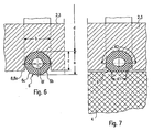
- the clamping element 6 has the shape an open or closed ring on it and it is located in an annular recess 8, z. B. an annular groove.
- the radial dimension a of the Clamping elements 6 in the radially relaxed state greater than the radial dimension c of the recess 8, so that the Clamping element projects beyond the recess 8 and the Slide the target sleeve 4 into the mold according to FIG. 7 is compressed in which it is under the radial Stress radially deformed and possibly also compressed.
- the axial dimension of the contact surface K1, with the Clamping element 6 rests against the target sleeve 4 is considerably large, especially if that Clamping element in the manner described above annular is formed, since in this case the contact surface K1 also over a majority or over the whole Extending extent.
- the clamping element 6 Due to the radial clamping voltage is the clamping element also on the base of the recess 8 flat. These Surface can be further enlarged when in axial Cut is rounded. In the embodiment of the Ausappelungsground rounded concave and the clamping element. 6 correspondingly convex rounded. It is advantageous form the clamping element 6 with such a width, that it under the radial clamping voltage to the Side walls of the recess 8 is applied, whereby the Contact area K2 is further increased, which is desirable is.
- the clamping element 6 is through formed a ring of circular cross-section, whose Inner diameter d the inner diameter of the Ringnutgroundes is equal to or slightly smaller, so that the so formed clamping ring with an elastic tension on Ringnutground rests. Due to the ring shape is the Clamping element 6 also held captive.
- the clamping element 6 is a Hollow body with a central cavity 6f. If that Clamping element 6 is a clamping ring, it can by a be formed endless hose, in particular one thick-walled hose whose wall thickness is about a quarter its cross-sectional dimension can amount.
- the at least externally rounded shape of the clamping element 6 is advantageous because they both sides insertion surfaces 6b, 6c forms when pushing the target sleeve or Inserting the carrier 2 automatically displacing the Allow clamping elements 6 in the recess 8.
- the elasticity of the clamping element 6 is at its Training in closed ring shape so great that it is too its assembly or disassembly over the outer diameter of the carrier 2 can be stretched and in the Annular groove 8a automatically contracted to the groove bottom, Preferably so far that it with a Contraction voltage is applied to the groove bottom.
Landscapes
- Chemical & Material Sciences (AREA)
- Engineering & Computer Science (AREA)
- Physics & Mathematics (AREA)
- Plasma & Fusion (AREA)
- Analytical Chemistry (AREA)
- Chemical Kinetics & Catalysis (AREA)
- Materials Engineering (AREA)
- Mechanical Engineering (AREA)
- Metallurgy (AREA)
- Organic Chemistry (AREA)
- Physical Vapour Deposition (AREA)
Claims (16)
- Dispositif porte-cible (1) comportant une douille de support (2), sur laquelle est disposée une enveloppe de cible, qui est formée par une douille de cible (4) et est emmanchée sur la douille de support (2) ou dans laquelle est enfoncée la douille de cible (4), au moins un élément de serrage (6) étant disposé de manière à réaliser un serrage entre la douille de support (2) et la douille de cible (4),
caractérisé en ce que
qu'il est prévu plusieurs éléments de serrage à action élastique (6), qui sont disposés d'une manière répartie sur la périphérie et sont formés par des ressorts respectifs, qui sont disposés dans un évidement (8) formé dans la surface enveloppe intérieure de la douille de cible (4) ou dans la surface enveloppe extérieure de la douille de support (2) d'une manière imperdable, sur la partie, qui les porte (douille de support ou douille de cible) et appuient élastiquement contre la surface enveloppe extérieure ou contre la surface enveloppe intérieure, qui est située en vis-à-vis de ces surfaces. - Dispositif porte-cible selon la revendication 1, caractérisé en ce que les éléments de serrage (6) possèdent, sur un côté ou sur les deux côtés tournés dans la direction axiale, des arêtes d'introduction arrondies ou obliques (6d, 6c).
- Dispositif porte-cible selon la revendication 1 ou 2, caractérisé en ce que les éléments de serrage (6) possèdent, pour appliquer leur pression de serrage, respectivement une branche de serrage (6a), qui applique la pression de serrage au moyen de sa partie d'extrémité libre.
- Dispositif porte-cible selon la revendication 3, caractérisé en ce que sur l'extrémité libre de la branche de serrage (6a) est disposée une branche d'introduction (6c), qui forme avec la branche de serrage (6a) une forme de toit anguleuse ou arrondie.
- Dispositif porte-cible selon la revendication 4, caractérisé en ce que l'extrémité libre de la branche d'introduction (6c) est supportée dans la position de serrage à l'encontre de la contrainte de serrage.
- Dispositif porte-cible selon l'une des revendications précédentes, caractérisé en ce que les éléments de serrage (6) sont serrés entre des parois latérales d'un évidement (8).
- Dispositif porte-cible selon l'une des revendications précédentes 3 à 6, caractérisé en ce que les éléments de serrage (6) sont formés respectivement par un ressort de forme coudée, notamment un ressort à lame coudée, comportant une branche de serrage (6a) et une branche de base (6e).
- Dispositif porte-cible selon la revendication 7, caractérisé en ce que la branche de base (6e) est serrée entre les parois latérales de l'évidement (8).
- Dispositif porte-cible selon la revendication 8, caractérisé en ce qu'un ou plusieurs évidements (8) sont formés sous la forme de rainures (8a, 8b), qui s'étendent dans la direction périphérique ou dans la direction d'axe ou sous une forme hélicoïdale.
- Dispositif porte-cible selon la revendication 9, caractérisé en ce que la ou les rainures, qui s'étendent dans la direction périphérique, est ou sont formées respectivement par une rainure annulaire.
- Dispositif porte-cible selon l'une des revendications précédentes, caractérisé en ce que les éléments de serrage (6) sont constitués chacun par un matériau déformable élastiquement et/ou pouvant être comprimés élastiquement.
- Dispositif porte-cible selon la revendication 11, caractérisé en ce que les éléments de serrage (6) sont réalisés en matière plastique et que des particules ou des fibres formées d'un matériau électriquement conducteur et/ou thermoconducteur sont insérées dans le matériau des éléments de serrage (6).
- Dispositif porte-cible selon la revendication 3 et l'une des revendications 15 à 16, caractérisé en ce que les éléments de serrage (6) possèdent au moins dans la zone d'une ouverture de l'évidement (8) une forme convexe - vue transversalement par rapport à la direction axiale du support -, notamment arrondie.
- Dispositif porte-cible selon la revendication 13, caractérisé en ce que les éléments de serrage (6) et l'évidement (8) sont réalisés avec une forme annulaire.
- Dispositif porte-cible selon la revendication 14, caractérisé en ce que les éléments de serrage (6) possèdent chacun au moins sur leur face intérieure une forme en coupe transversale arrondie convexe et que de préférence le fond de l'évidement possède une forme arrondie correspondante.
- Dispositif porte-cible selon l'une des revendications précédentes, caractérisé en ce que la longueur (L1) de la douille de support (2) est supérieure à la longueur (L2) de la douille de cible (4) et que respectivement au moins une partie de limitation de forme annulaire (9) est fixée de façon amovible sur une extrémité ou sur les deux extrémités de la douille de cible (4).
Applications Claiming Priority (3)
| Application Number | Priority Date | Filing Date | Title |
|---|---|---|---|
| DE10231203A DE10231203B4 (de) | 2002-07-10 | 2002-07-10 | Targetträgeranordnung |
| DE10231203 | 2002-07-10 | ||
| PCT/EP2003/006518 WO2004007791A1 (fr) | 2002-07-10 | 2003-06-20 | Ensemble porte-cible |
Publications (2)
| Publication Number | Publication Date |
|---|---|
| EP1518006A1 EP1518006A1 (fr) | 2005-03-30 |
| EP1518006B1 true EP1518006B1 (fr) | 2005-10-05 |
Family
ID=30009885
Family Applications (1)
| Application Number | Title | Priority Date | Filing Date |
|---|---|---|---|
| EP03763647A Expired - Lifetime EP1518006B1 (fr) | 2002-07-10 | 2003-06-20 | Ensemble porte-cible |
Country Status (4)
| Country | Link |
|---|---|
| US (1) | US7811429B2 (fr) |
| EP (1) | EP1518006B1 (fr) |
| DE (2) | DE10231203B4 (fr) |
| WO (1) | WO2004007791A1 (fr) |
Families Citing this family (25)
| Publication number | Priority date | Publication date | Assignee | Title |
|---|---|---|---|---|
| KR100867620B1 (ko) | 2005-05-25 | 2008-11-10 | 삼성전자주식회사 | 다중 입력 다중 출력 시스템에서 공간 분할 다중 접속을위해 사용자를 선택하기 위한 장치 및 방법 |
| PT1752556E (pt) | 2005-08-02 | 2008-01-22 | Applied Materials Gmbh & Co Kg | Cátodo tubular para aplicação em processo de pulverização catódica |
| DE102006009749A1 (de) | 2006-03-02 | 2007-09-06 | FNE Forschungsinstitut für Nichteisen-Metalle Freiberg GmbH | Targetanordnung |
| US20140021044A1 (en) * | 2006-10-02 | 2014-01-23 | Thermal Conductive Bonding, Inc. | Elastomer Bonded Rotary Sputtering Target |
| US20080078268A1 (en) | 2006-10-03 | 2008-04-03 | H.C. Starck Inc. | Process for preparing metal powders having low oxygen content, powders so-produced and uses thereof |
| US20080145688A1 (en) | 2006-12-13 | 2008-06-19 | H.C. Starck Inc. | Method of joining tantalum clade steel structures |
| US8197894B2 (en) | 2007-05-04 | 2012-06-12 | H.C. Starck Gmbh | Methods of forming sputtering targets |
| DE102007044651B4 (de) | 2007-09-18 | 2011-07-21 | W.C. Heraeus GmbH, 63450 | Rohrsputtertarget mit grabenförmig strukturierter Außenfläche des Trägerrohres sowie Verfahren zu seiner Herstellung |
| US8246903B2 (en) | 2008-09-09 | 2012-08-21 | H.C. Starck Inc. | Dynamic dehydriding of refractory metal powders |
| EP2180501A1 (fr) * | 2008-10-24 | 2010-04-28 | Applied Materials, Inc. | Base de cible de pulvérisation rotative, cible de pulvérisation rotative, installation de revêtement, procédé de fabrication d'une cible de pulvérisation rotative, moyen de connexion de la base de cible et procédé de connexion d'un dispositif de base cible rotative pour installations de pulvérisation à un support de base de cible |
| US20100101946A1 (en) * | 2008-10-24 | 2010-04-29 | Applied Materials, Inc. | Rotatable sputter target backing cylinder, rotatable sputter target, methods of producing and restoring a rotatable sputter target, and coating installation |
| EP2180502A1 (fr) * | 2008-10-24 | 2010-04-28 | Applied Materials, Inc. | Cylindre de support de cible de pulvérisation rotative, cible de pulvérisation rotative, son procédé de fabrication, et installation de revêtement |
| EP2180500A1 (fr) * | 2008-10-24 | 2010-04-28 | Applied Materials, Inc. | Cylindre de support de cible de pulvérisation rotative, cible de pulvérisation rotative, procédés de fabrication et rétablissement d'une cible de pulvérisation rotative et installation de revêtement |
| JP5762964B2 (ja) * | 2008-10-24 | 2015-08-12 | アプライド マテリアルズ インコーポレイテッドApplied Materials,Incorporated | 回転可能なスパッタターゲットベース、回転可能なスパッタターゲット、コーティング装置、回転可能なスパッタターゲットを作成する方法、ターゲットベース接続手段 |
| EP2276055A1 (fr) * | 2009-07-13 | 2011-01-19 | Applied Materials, Inc. | Tuyau de support de cible, cible cylindrique et ensemble de cible cylindrique |
| DE102009050565A1 (de) * | 2009-10-23 | 2011-04-28 | Sindlhauser Materials Gmbh | Sputtertargetanordnung |
| EP2365515A1 (fr) * | 2010-03-09 | 2011-09-14 | Applied Materials, Inc. | Cible rotative, tube de support, installation de pulvérisation et procédé de fabrication d'une cible rotative |
| TWI393796B (zh) * | 2010-06-02 | 2013-04-21 | Solar Applied Mat Tech Corp | 中空狀靶材組件 |
| RU2013103041A (ru) * | 2010-07-12 | 2014-08-20 | Мэтиреон Эдвансд Мэтириэлз Текнолоджиз Энд Сервисез Инк. | Узел соединения опорной трубки с вращающейся мишенью |
| CN102338598B (zh) * | 2010-07-19 | 2014-02-19 | 光洋应用材料科技股份有限公司 | 中空状靶材组件 |
| EP2420589B1 (fr) * | 2010-08-19 | 2013-03-20 | Solar Applied Materials Technology Corp. | Ensemble de cible creuse |
| US9120183B2 (en) | 2011-09-29 | 2015-09-01 | H.C. Starck Inc. | Methods of manufacturing large-area sputtering targets |
| DE102013100383B4 (de) * | 2013-01-15 | 2019-12-05 | VON ARDENNE Asset GmbH & Co. KG | Magnetronanordnung |
| DE102013100382B4 (de) * | 2013-01-15 | 2019-12-05 | VON ARDENNE Asset GmbH & Co. KG | Magnetronanordnung |
| US9328410B2 (en) | 2013-10-25 | 2016-05-03 | First Solar, Inc. | Physical vapor deposition tile arrangement and physical vapor deposition arrangement |
Family Cites Families (12)
| Publication number | Priority date | Publication date | Assignee | Title |
|---|---|---|---|---|
| US4356073A (en) | 1981-02-12 | 1982-10-26 | Shatterproof Glass Corporation | Magnetron cathode sputtering apparatus |
| JPH01193463A (ja) * | 1988-01-29 | 1989-08-03 | Matsushita Electric Ind Co Ltd | 真空加工装置の真空シール部構造 |
| US4851798A (en) | 1988-03-31 | 1989-07-25 | Rca Licensing Corporation | Unitary tuning structure |
| US4820397A (en) * | 1988-04-04 | 1989-04-11 | Tosoh Smd, Inc. | Quick change sputter target assembly |
| US5147521A (en) * | 1991-05-20 | 1992-09-15 | Tosoh Smd, Inc. | Quick change sputter target assembly |
| US5487822A (en) * | 1993-11-24 | 1996-01-30 | Applied Materials, Inc. | Integrated sputtering target assembly |
| DE4414470A1 (de) * | 1994-04-26 | 1995-11-02 | Leybold Ag | Zerstäuberkathode |
| US5591314A (en) * | 1995-10-27 | 1997-01-07 | Morgan; Steven V. | Apparatus for affixing a rotating cylindrical magnetron target to a spindle |
| JP4614037B2 (ja) * | 2000-09-08 | 2011-01-19 | Agcセラミックス株式会社 | 円筒状ターゲット |
| CA2418807A1 (fr) * | 2000-09-08 | 2003-02-05 | Asahi Glass Company, Limited | Cible cylindrique et procede de fabrication |
| US6409897B1 (en) * | 2000-09-20 | 2002-06-25 | Poco Graphite, Inc. | Rotatable sputter target |
| DE10102493B4 (de) * | 2001-01-19 | 2007-07-12 | W.C. Heraeus Gmbh | Rohrförmiges Target und Verfahren zur Herstellung eines solchen Targets |
-
2002
- 2002-07-10 DE DE10231203A patent/DE10231203B4/de not_active Expired - Lifetime
-
2003
- 2003-06-20 EP EP03763647A patent/EP1518006B1/fr not_active Expired - Lifetime
- 2003-06-20 US US10/520,755 patent/US7811429B2/en active Active
- 2003-06-20 WO PCT/EP2003/006518 patent/WO2004007791A1/fr not_active Ceased
- 2003-06-20 DE DE50301326T patent/DE50301326D1/de not_active Expired - Lifetime
Also Published As
| Publication number | Publication date |
|---|---|
| US7811429B2 (en) | 2010-10-12 |
| US20050224342A1 (en) | 2005-10-13 |
| EP1518006A1 (fr) | 2005-03-30 |
| WO2004007791A1 (fr) | 2004-01-22 |
| DE50301326D1 (de) | 2006-02-16 |
| DE10231203A1 (de) | 2004-02-05 |
| DE10231203B4 (de) | 2009-09-10 |
Similar Documents
| Publication | Publication Date | Title |
|---|---|---|
| EP1518006B1 (fr) | Ensemble porte-cible | |
| DE2819744C2 (de) | Scharnier, insbesondere Brillenscharnier | |
| EP1211137B1 (fr) | Element pour connexion | |
| EP0505719A1 (fr) | Articulation à rotule | |
| EP0745829B1 (fr) | Câble de mesure et capteur avec boítier en forme de coquille | |
| EP0214192A1 (fr) | Joint sous forme de brosses. | |
| EP0295319A1 (fr) | Cylindre gravé composé d'un noyau et d'une douille amovible | |
| EP3228891B1 (fr) | Dispositif et procédé destiné à faire reculer un coussinet de palier sorti de son logement sur un arbre | |
| DE29706849U1 (de) | Längenverstellbares Rohr, insbesondere für Ski- oder Wanderstöcke | |
| EP1548483B1 (fr) | Objectif pour un microscope avec des montures correctives axialement adjustables | |
| EP4103856B1 (fr) | Ensemble palier | |
| DE19721611C2 (de) | Vakuumkammer | |
| EP2083237B1 (fr) | Faisceau de canons d'une arme à poing | |
| DE29500415U1 (de) | Bausatz für Kleinmöbel | |
| DE29903592U1 (de) | Flüssigkeitsgefäß | |
| EP0269666A1 (fr) | Systeme de fixation. | |
| DE3535778A1 (de) | Schwinungsdaempfer fuer elektrische freileitungen | |
| DE3437089A1 (de) | Klemmvorrichtung | |
| DE102007046276B3 (de) | Drehbetätiger für eine Einstelleinrichtung sowie Einstelleinrichtung | |
| DE3014600C2 (de) | Anschlußarmatur für einen Isolatorstab aus glasfaserverstärktem Kunststoff | |
| EP3012504B1 (fr) | Adaptateur | |
| DE2516142C3 (de) | Drehkippgelenk für Leuchten | |
| DE9405817U1 (de) | Feuchtigkeitsgeschützte Fassung für Leuchtstofflampen | |
| WO1980001621A1 (fr) | Isolateur composite pour haute tension | |
| DE7712593U1 (de) | Stösselschaltgerät |
Legal Events
| Date | Code | Title | Description |
|---|---|---|---|
| PUAI | Public reference made under article 153(3) epc to a published international application that has entered the european phase |
Free format text: ORIGINAL CODE: 0009012 |
|
| 17P | Request for examination filed |
Effective date: 20041206 |
|
| AK | Designated contracting states |
Kind code of ref document: A1 Designated state(s): AT BE BG CH CY CZ DE DK EE ES FI FR GB GR HU IE IT LI LU MC NL PT RO SE SI SK TR |
|
| GRAP | Despatch of communication of intention to grant a patent |
Free format text: ORIGINAL CODE: EPIDOSNIGR1 |
|
| RBV | Designated contracting states (corrected) |
Designated state(s): DE FR GB |
|
| GRAS | Grant fee paid |
Free format text: ORIGINAL CODE: EPIDOSNIGR3 |
|
| GRAA | (expected) grant |
Free format text: ORIGINAL CODE: 0009210 |
|
| AK | Designated contracting states |
Kind code of ref document: B1 Designated state(s): DE FR GB |
|
| REG | Reference to a national code |
Ref country code: GB Ref legal event code: FG4D Free format text: NOT ENGLISH |
|
| GBT | Gb: translation of ep patent filed (gb section 77(6)(a)/1977) |
Effective date: 20051005 |
|
| REF | Corresponds to: |
Ref document number: 50301326 Country of ref document: DE Date of ref document: 20060216 Kind code of ref document: P |
|
| ET | Fr: translation filed | ||
| PLBE | No opposition filed within time limit |
Free format text: ORIGINAL CODE: 0009261 |
|
| STAA | Information on the status of an ep patent application or granted ep patent |
Free format text: STATUS: NO OPPOSITION FILED WITHIN TIME LIMIT |
|
| 26N | No opposition filed |
Effective date: 20060706 |
|
| REG | Reference to a national code |
Ref country code: FR Ref legal event code: PLFP Year of fee payment: 13 |
|
| REG | Reference to a national code |
Ref country code: FR Ref legal event code: PLFP Year of fee payment: 14 |
|
| REG | Reference to a national code |
Ref country code: FR Ref legal event code: PLFP Year of fee payment: 15 |
|
| REG | Reference to a national code |
Ref country code: FR Ref legal event code: PLFP Year of fee payment: 16 |
|
| PGFP | Annual fee paid to national office [announced via postgrant information from national office to epo] |
Ref country code: GB Payment date: 20220623 Year of fee payment: 20 |
|
| PGFP | Annual fee paid to national office [announced via postgrant information from national office to epo] |
Ref country code: FR Payment date: 20220622 Year of fee payment: 20 |
|
| PGFP | Annual fee paid to national office [announced via postgrant information from national office to epo] |
Ref country code: DE Payment date: 20220627 Year of fee payment: 20 |
|
| REG | Reference to a national code |
Ref country code: DE Ref legal event code: R071 Ref document number: 50301326 Country of ref document: DE |
|
| REG | Reference to a national code |
Ref country code: GB Ref legal event code: PE20 Expiry date: 20230619 |
|
| PG25 | Lapsed in a contracting state [announced via postgrant information from national office to epo] |
Ref country code: GB Free format text: LAPSE BECAUSE OF EXPIRATION OF PROTECTION Effective date: 20230619 |