EP1518006B1 - Target support assembly - Google Patents
Target support assembly Download PDFInfo
- Publication number
- EP1518006B1 EP1518006B1 EP03763647A EP03763647A EP1518006B1 EP 1518006 B1 EP1518006 B1 EP 1518006B1 EP 03763647 A EP03763647 A EP 03763647A EP 03763647 A EP03763647 A EP 03763647A EP 1518006 B1 EP1518006 B1 EP 1518006B1
- Authority
- EP
- European Patent Office
- Prior art keywords
- target
- support assembly
- assembly according
- clamping
- sleeve
- Prior art date
- Legal status (The legal status is an assumption and is not a legal conclusion. Google has not performed a legal analysis and makes no representation as to the accuracy of the status listed.)
- Expired - Lifetime
Links
- 239000000463 material Substances 0.000 claims description 14
- 239000004020 conductor Substances 0.000 claims description 7
- 238000003780 insertion Methods 0.000 claims description 7
- 230000037431 insertion Effects 0.000 claims description 7
- 239000002245 particle Substances 0.000 claims description 3
- 229920002994 synthetic fiber Polymers 0.000 claims 1
- 239000011248 coating agent Substances 0.000 description 5
- 238000000576 coating method Methods 0.000 description 5
- 230000017525 heat dissipation Effects 0.000 description 5
- 238000004544 sputter deposition Methods 0.000 description 5
- 239000000758 substrate Substances 0.000 description 5
- 239000002184 metal Substances 0.000 description 4
- OKTJSMMVPCPJKN-UHFFFAOYSA-N Carbon Chemical compound [C] OKTJSMMVPCPJKN-UHFFFAOYSA-N 0.000 description 2
- 230000004323 axial length Effects 0.000 description 2
- 229910052799 carbon Inorganic materials 0.000 description 2
- 239000000835 fiber Substances 0.000 description 2
- 229920001296 polysiloxane Polymers 0.000 description 2
- 229910000831 Steel Inorganic materials 0.000 description 1
- 238000005452 bending Methods 0.000 description 1
- 230000015572 biosynthetic process Effects 0.000 description 1
- 230000008602 contraction Effects 0.000 description 1
- 238000000151 deposition Methods 0.000 description 1
- 238000011161 development Methods 0.000 description 1
- 230000018109 developmental process Effects 0.000 description 1
- 230000000694 effects Effects 0.000 description 1
- 239000013013 elastic material Substances 0.000 description 1
- 238000010285 flame spraying Methods 0.000 description 1
- 239000005329 float glass Substances 0.000 description 1
- 239000011521 glass Substances 0.000 description 1
- 238000004519 manufacturing process Methods 0.000 description 1
- 238000002360 preparation method Methods 0.000 description 1
- 238000003825 pressing Methods 0.000 description 1
- 239000010959 steel Substances 0.000 description 1
- 239000002470 thermal conductor Substances 0.000 description 1
Images


Classifications
-
- H—ELECTRICITY
- H01—ELECTRIC ELEMENTS
- H01J—ELECTRIC DISCHARGE TUBES OR DISCHARGE LAMPS
- H01J37/00—Discharge tubes with provision for introducing objects or material to be exposed to the discharge, e.g. for the purpose of examination or processing thereof
- H01J37/32—Gas-filled discharge tubes
- H01J37/34—Gas-filled discharge tubes operating with cathodic sputtering
- H01J37/3411—Constructional aspects of the reactor
- H01J37/3435—Target holders (includes backing plates and endblocks)
-
- C—CHEMISTRY; METALLURGY
- C23—COATING METALLIC MATERIAL; COATING MATERIAL WITH METALLIC MATERIAL; CHEMICAL SURFACE TREATMENT; DIFFUSION TREATMENT OF METALLIC MATERIAL; COATING BY VACUUM EVAPORATION, BY SPUTTERING, BY ION IMPLANTATION OR BY CHEMICAL VAPOUR DEPOSITION, IN GENERAL; INHIBITING CORROSION OF METALLIC MATERIAL OR INCRUSTATION IN GENERAL
- C23C—COATING METALLIC MATERIAL; COATING MATERIAL WITH METALLIC MATERIAL; SURFACE TREATMENT OF METALLIC MATERIAL BY DIFFUSION INTO THE SURFACE, BY CHEMICAL CONVERSION OR SUBSTITUTION; COATING BY VACUUM EVAPORATION, BY SPUTTERING, BY ION IMPLANTATION OR BY CHEMICAL VAPOUR DEPOSITION, IN GENERAL
- C23C14/00—Coating by vacuum evaporation, by sputtering or by ion implantation of the coating forming material
- C23C14/22—Coating by vacuum evaporation, by sputtering or by ion implantation of the coating forming material characterised by the process of coating
- C23C14/34—Sputtering
- C23C14/3407—Cathode assembly for sputtering apparatus, e.g. Target
Definitions
- the invention relates to a target carrier assembly according to the preamble of claim 1.
- the coating material by Sputtering and sputtering on the substrate deposit. It forms a target coat on one Support tube sits and with this a target carrier assembly.
- a target carrier assembly Such a device for sputtering is z. B. in EP 0 070 899 B1.
- the Cover material by flame spraying circulating on the Apply support tube, whereby the target shell formed is and forms a permanent unit with the support tube.
- the invention is based on the object at a Target carrier arrangement according to the preamble of claim 1 the preparation of the target jacket or the Target carrier assembly and / or the attachment of the Target mantels on the carrier to simplify.
- the target carrier assembly is the Target jacket formed by a Targetülse, which on the Carrier pushed and heat-conducting and electric is fixed conductively.
- a Targetgse which on the Carrier pushed and heat-conducting and electric is fixed conductively.
- the inventive Target sleeve can be in contrast to the prior art prefabricate and store, where appropriate, simply and quickly mountable by sliding on the carrier and, if appropriate, can be removed again.
- the assembly can in an associated device for atomizing the Coating material done, the carrier only partially needs to be dismantled, namely only so far that the Target sleeve is pushed from one end.
- the Invention thus allows several advantages, both the target sleeve itself also as the target carrier assembly affect.
- the at least one elastically effective clamping element is used the fixation of the target sleeve in its axial direction and / or circumferential direction on the carrier.
- a thermal conductor and / or form electrical conductor when it is made of heat conducting Material and / or electrically conductive material consists.
- There are several elastically effective according to claim 1 Provide clamping elements, preferably on the circumference are distributed, causing the Increase fixation forces and / or heat conduction let and / or improve the electrical contact leaves.
- At least one clamping element in a recess of the inner circumferential surface of the target sleeve or preferably the outer circumferential surface of the carrier so to arrange that a clamping arm of the clamping element on the Inner circumferential surface or the outer circumferential surface protrudes, is automatically bent when mounting the Target sleeve and with a radial stress on the opposite Outer or inner circumferential surface is present.
- the base of the clamping element in the To fix recess so that it held captive is.
- the clamping element can for example by an angle be formed, one leg of which is the base of Clamping elements forms and the other leg against the other part presses elastically.
- the at least one clamping element made of an elastic deformable material to form in the clamping state presses radially against the target sleeve and so soft is that it is flat to the target sleeve and his Abutment creates, which due to the large Plant surface perform a powerful heat dissipation can.
- Suitable for this purpose a plastic z.
- silicone in the electrical conductive or thermally conductive particles or elements, e.g. B. Fibers, for example of metal or carbon are embedded.
- a clamping element in ring form to provide that in an annular groove in which the clamping element carrying component sits and this component radially so far surmounted that there is a radial clamping voltage between the target sleeve and the carrier sits.
- one is round cross-sectional shape of the clamping element advantageous because the curves pointing in both axial directions Forming entry surfaces, which are when pushing the Targets sleeve an automatic Dodge and Elastic Compressing the clamping element cause.
- Another Advantage of the ring shape is that such Clamping element held captive due to the ring shape is and therefore it requires no further holding means.
- the target sleeve according to the invention needs in Circumferential direction not to be closed, although the in Circumferentially closed form in particular Strength and Gargesn is advantageous.
- the Target sleeve can therefore be longitudinally slotted or it can be a not closed in the circumferential direction Sleeve section act.
- the target carrier assembly may comprise a tube cathode in one Device for sputtering the material of the Target sleeve and in a vacuum chamber of the Device next to or above a support for a substrate be arranged on which the atomized material is knocked down.
- the target carrier assembly is suitable preferably for depositing a nebulizing Material layer on a substrate forming Glass pane.
- Target carrier assembly is a carrier 2, for example by a substantially cylindrical support sleeve. 3 may be formed, and a target sleeve 4, which with small movement play on the support 2 pushed and by at least one fixing element in their Fixed circumferential direction and / or in its axial direction is.
- the carrier 2 is made of metal, preferably steel. He has at its ends at L only hinted shown fastening means, with which he in a Pivot bearing is rotatably mounted about its central axis 2a, the part of a device for atomizing and coating (Sputtering) on a flat substrate, not shown z. B. float glass is.
- the target sleeve 3 is also made made of metal.
- the axial length L1 of the carrier 2 is larger than that axial length L2 of the target sleeve 4, the latter in the Middle region of the carrier 2 is arranged so that this projects beyond the carrier 2 at both ends.
- At least a fixing element 5 is an elastically effective Clamping element 6, in the embodiment of consists of elastic material and one between the Carrier 2 and the target sleeve 4 radially effective Clamping voltage exerts. It may be on the target sleeve 4th or preferably on the carrier 2, as it is Embodiment shows.
- FIG. 4 and 5 has the clamping element 6 a clamping leg 6 a, in its relaxed release position shown in FIG. 4 the associated lateral surface or hollow cylindrical joint 7 surmounted between the carrier 2 and the target sleeve 4.
- the carrier sleeve 4 by pushing it onto the carrier 2 becomes obliquely extending with respect to the joint 7 and an oblique or rounded insertion edge 6b forming clamping legs 6a automatically inflected, where he with its elastic bending stress generated thereby radially effective elastic tension between the carrier 2 and the target sleeve 4 generates the fixation guaranteed.
- clamping leg 6a its free end with an opposite oblique or rounded insertion leg 6c form, so that the above-described automatic Turning the clamping leg 6a automatically when Sliding the target sleeve 4 either of the one or done from the other side.
- the clamping leg 6a is preferably at its base end integrally connected to a clamping element base 6d, which in a recess 8 is arranged and fixed therein, for Example by a screw, not shown.
- the clamping element base 6d by a with Base leg 6e connected to clamping leg 6a formed, which thereby be fixed in the recess 8 can be that its length is dimensioned slightly larger than the width b of the recess 8, so that the base leg 6e between the side walls of the recess 8 through Pressing is clamped.
- the insertion leg 6c may be sized so long that its free end in the clamping position at that Clamping element 6 supporting part, here on the carrier 2 or on Bottom of the recess 8 or on the base leg 6d, is supported, as shown in FIG. 5. This can be increase the clamping force of the clamping element 6.
- the Clamping element 6 is preferably by an angular Spring, in particular leaf spring, formed.
- the clamping element 6 can not only the fixing function but also the heat dissipation from the target sleeve 4 to Carrier 2 out and / or the electrical line between serve the carrier 2 and the target sleeve 4, when it is off thermally conductive material and / or from electrical consists of conductive material.
- fixation forces and / or the Heat dissipation and / or the electrical line is it advantageous to arrange a plurality of clamping elements 6, the preferably distributed over the entire circumference, so that a substantially on the entire circumference distributed function results.
- One or more recesses 8 can each by a or more circumferentially extending Ring grooves 8a or one or more in the Axial direction 2a extending longitudinal grooves 8b be formed in each case a plurality of such grooves 8a, 8b in the region of Targethülse 4 axially or circumferentially approximately can be arranged evenly distributed. It is also possible, one or more distributed on the perimeter to provide arranged helical grooves (not ) Shown.
- the optionally additional axial fixation at the ends of the Targethülse 4 preferably annular boundary parts. 9 sitting on the support 2 and be detachably connected to it, for example, by suggestively illustrated screws 11 screwed, the axial fixation of the Target sleeve 4 on the carrier 2 effect.
- this clamping element 6 so elastically deformable and / or elastic compressible material is that it is due to its radial clamping voltage both to the target sleeve as applied to the carrier surface and thus each forms a large contact surface, at which the electrical Conduction and heat dissipation done.
- the thermal conductivity and electrical conductivity of the elastically deformable or elastically compressible Material of the clamping element 6 can by embedding Particles or fibers of electrically conductive and thermally conductive material, in particular of metal or Carbon take place, wherein the elastic base material made of plastic, in particular silicone, may exist.
- the clamping element 6 has the shape an open or closed ring on it and it is located in an annular recess 8, z. B. an annular groove.
- the radial dimension a of the Clamping elements 6 in the radially relaxed state greater than the radial dimension c of the recess 8, so that the Clamping element projects beyond the recess 8 and the Slide the target sleeve 4 into the mold according to FIG. 7 is compressed in which it is under the radial Stress radially deformed and possibly also compressed.
- the axial dimension of the contact surface K1, with the Clamping element 6 rests against the target sleeve 4 is considerably large, especially if that Clamping element in the manner described above annular is formed, since in this case the contact surface K1 also over a majority or over the whole Extending extent.
- the clamping element 6 Due to the radial clamping voltage is the clamping element also on the base of the recess 8 flat. These Surface can be further enlarged when in axial Cut is rounded. In the embodiment of the Ausappelungsground rounded concave and the clamping element. 6 correspondingly convex rounded. It is advantageous form the clamping element 6 with such a width, that it under the radial clamping voltage to the Side walls of the recess 8 is applied, whereby the Contact area K2 is further increased, which is desirable is.
- the clamping element 6 is through formed a ring of circular cross-section, whose Inner diameter d the inner diameter of the Ringnutgroundes is equal to or slightly smaller, so that the so formed clamping ring with an elastic tension on Ringnutground rests. Due to the ring shape is the Clamping element 6 also held captive.
- the clamping element 6 is a Hollow body with a central cavity 6f. If that Clamping element 6 is a clamping ring, it can by a be formed endless hose, in particular one thick-walled hose whose wall thickness is about a quarter its cross-sectional dimension can amount.
- the at least externally rounded shape of the clamping element 6 is advantageous because they both sides insertion surfaces 6b, 6c forms when pushing the target sleeve or Inserting the carrier 2 automatically displacing the Allow clamping elements 6 in the recess 8.
- the elasticity of the clamping element 6 is at its Training in closed ring shape so great that it is too its assembly or disassembly over the outer diameter of the carrier 2 can be stretched and in the Annular groove 8a automatically contracted to the groove bottom, Preferably so far that it with a Contraction voltage is applied to the groove bottom.
Description
Die Erfindung bezieht sich auf eine Targetträgeranordnung nach dem Oberbegriff des Anspruchs 1.The invention relates to a target carrier assembly according to the preamble of claim 1.
Zum Aufbringen einer Beschichtung auf ein im wesentlichen ebenes Substrat ist es bekannt, das Überzugsmaterial durch Kathodenzerstäubung zu zerstäuben und auf dem Substrat abzuscheiden. Dabei bildet ein Targetmantel, der auf einem Tragrohr sitzt und mit diesem eine Targetträgeranordnung. Eine solche Vorrichtung für Kathodenzerstäubung ist z. B. in der EP 0 070 899 B1 beschrieben. Zum Aufbringen des Beschichtungsmaterials auf ein Tragrohr ist es üblich, das Überzugsmaterial durch Flammspritzen umlaufend auf das Tragrohr aufzutragen, wodurch der Targetmantel gebildet wird und mit dem Tragrohr eine unlösbare Einheit bildet. Diese bekannten Maßnahmen sind sowohl zur Bildung des Targetmantels selbst als auch zur Anbringung des Targetmantels am Tragrohr aufwendig.For applying a coating to a substantially even substrate is known, the coating material by Sputtering and sputtering on the substrate deposit. It forms a target coat on one Support tube sits and with this a target carrier assembly. Such a device for sputtering is z. B. in EP 0 070 899 B1. To apply the Coating material on a support tube, it is common, the Cover material by flame spraying circulating on the Apply support tube, whereby the target shell formed is and forms a permanent unit with the support tube. These known measures are both for the formation of the Target mantels themselves as well as for attaching the Target mantle on the support tube consuming.
Der Erfindung liegt die Aufgabe zu Grunde, bei einer Targetträgeranordnung nach dem Oberbegriff des Anspruchs 1 die Herstellung des Targetmantels oder der Targetträgeranordnung und/oder die Anbringung des Targetmantels am Träger zu vereinfachen.The invention is based on the object at a Target carrier arrangement according to the preamble of claim 1 the preparation of the target jacket or the Target carrier assembly and / or the attachment of the Target mantels on the carrier to simplify.
Diese Aufgabe wird durch die Merkmale des Anspruchs 1 gelöst.This object is achieved by the features of claim 1 solved.
Bei der erfindungsgemäßen Targetträgeranordnung ist der Targetmantel durch eine Targethülse gebildet, die auf den Träger aufgeschoben und wärmeleitend sowie elektrisch leitend fixiert ist. Dabei sind zwischen dem Träger und der Targethülse mehrere elastisch wirksame Klemmelemente angeordnet die auf dem umfang verteilt angeordnet sind und jeweils durch eine Feder gebildet sind. Die erfindungsgemäße Targethülse läßt sich im Gegensatz zum Stand der Technik vorfertigen und gegebenenfalls lagern, wobei sie einfach und schnell durch Aufschieben auf den Träger montierbar und gegebenenfalls wieder demontierbar ist. Die Montage kann in einer zugehörigen Vorrichtung zum Zerstäuben des Überzugsmaterials erfolgen, wobei der Träger nur zum Teil demontiert zu werden braucht, nämlich nur soweit, daß die Targethülse von einem Ende her aufschiebbar ist. Die Erfindung ermöglicht somit mehrere Vorteile, die sowohl die Targethülse selbst auch als die Targetträgeranordnung betreffen.In the target carrier assembly according to the invention is the Target jacket formed by a Targetülse, which on the Carrier pushed and heat-conducting and electric is fixed conductively. Here are between the carrier and the Target sleeve several elastic arranged effective clamping elements which are arranged distributed on the circumference and each formed by a spring. The inventive Target sleeve can be in contrast to the prior art prefabricate and store, where appropriate, simply and quickly mountable by sliding on the carrier and, if appropriate, can be removed again. The assembly can in an associated device for atomizing the Coating material done, the carrier only partially needs to be dismantled, namely only so far that the Target sleeve is pushed from one end. The Invention thus allows several advantages, both the target sleeve itself also as the target carrier assembly affect.
Vorteilhafte Weiterbildungen der Erfindung sind in den Unteransprüchen beschrieben.Advantageous developments of the invention are in the Subclaims described.
Das wenigstens eine elastisch wirksame Klemmelement dient der Fixierung der Targethülse in ihrer Achsrichtung und/oder Umfangsrichtung auf dem Träger. Außerdem kann das elastische Klemmelement einen thermischen Leiter und/oder elektrischen Leiter bilden, wenn es aus wärmeleitendem Material und/oder aus elektrisch leitendem Material besteht. Es sind nach Anspruch 1 mehrere elastisch wirksame Klemmelemente vorzusehen, die vorzugsweise auf dem Umfang verteilt angeordnet sind, wodurch sich die Fixierungskräfte und/oder die Wärmeleitung vergrößern lassen und/oder die elektrische Kontaktierung verbessern läßt.The at least one elastically effective clamping element is used the fixation of the target sleeve in its axial direction and / or circumferential direction on the carrier. In addition, that can elastic clamping element a thermal conductor and / or form electrical conductor when it is made of heat conducting Material and / or electrically conductive material consists. There are several elastically effective according to claim 1 Provide clamping elements, preferably on the circumference are distributed, causing the Increase fixation forces and / or heat conduction let and / or improve the electrical contact leaves.
Es ist vorteilhaft, das wenigstens eine Klemmelement in einer Ausnehmung der Innenmantelfläche der Targethülse oder vorzugsweise der Außenmantelfläche des Trägers so anzuordnen, daß ein Klemmarm des Klemmelements über die Innenmantelfläche bzw. die Außenmantelfläche vorsteht, beim Montieren der Targethülse selbsttätig eingebogen wird und mit einer radialen Spannung an der gegenüberliegenden Außen- bzw. Innenmantelfläche anliegt. Dabei ist es besonders vorteilhaft, die Basis des Klemmelements in der Ausnehmung zu fixieren, so daß es unverlierbar gehalten ist. Das Klemmelement kann zum Beispiel durch einen Winkel gebildet sein, dessen einer Schenkel die Basis des Klemmelements bildet und dessen anderer Schenkel gegen das andere Teil elastisch drückt. Eine einfach und kostengünstige Herstellung ist insbesondere dann möglich, wenn eine oder mehrere Ringnuten oder axial oder wendelförmig verlaufende Nuten vorgesehen sind, in denen mehrere elastisch wirksame Klemmelemente einsetzbar sind.It is advantageous that at least one clamping element in a recess of the inner circumferential surface of the target sleeve or preferably the outer circumferential surface of the carrier so to arrange that a clamping arm of the clamping element on the Inner circumferential surface or the outer circumferential surface protrudes, is automatically bent when mounting the Target sleeve and with a radial stress on the opposite Outer or inner circumferential surface is present. That's it Particularly advantageous, the base of the clamping element in the To fix recess so that it held captive is. The clamping element can for example by an angle be formed, one leg of which is the base of Clamping elements forms and the other leg against the other part presses elastically. An easy and cost-effective production is possible in particular then if one or more annular grooves or axial or helically extending grooves are provided, in which several elastically effective clamping elements can be used.
Zwecks einer guten Wärmeableitung der im Funktionsbetrieb der Targethülse entstehenden Wärme ist es vorteilhaft, das wenigstens eine Klemmelement aus einem elastisch verformbaren Material zu bilden, das im Klemmzustand radial gegen die Targethülse drückt und dabei so weich ist, daß es sich flächig an die Targethülse und seinem Widerlager anlegt, wodurch aufgrund der großen Anlagefläche eine leistungsfähige Wärmeableitung erfolgen kann. Dies gilt sowohl für die Anlage des Klemmelements an der Targethülse als auch am Träger. Vorteilhaft sind solche Materialien, die trotz ihrer elastischen Verformbarkeit bzw. elastischen Komprimierbarkeit elektrisch leitend und wärmeleitend sind. Hierzu eignet sich ein Kunststoff z. B. Silikon, in den elektrisch leitende oder wärmeleitende Partikel oder Elemente, z. B. Fasern, beispielsweise aus Metall oder Kohlenstoff eingebettet sind.For a good heat dissipation in the functional operation the Target sleeve resulting heat, it is advantageous to the at least one clamping element made of an elastic deformable material to form, in the clamping state presses radially against the target sleeve and so soft is that it is flat to the target sleeve and his Abutment creates, which due to the large Plant surface perform a powerful heat dissipation can. This applies both to the attachment of the clamping element the target sleeve as well as the carrier. Are advantageous such materials, in spite of their elastic Deformability or elastic compressibility are electrically conductive and thermally conductive. Suitable for this purpose a plastic z. As silicone, in the electrical conductive or thermally conductive particles or elements, e.g. B. Fibers, for example of metal or carbon are embedded.
Es ist besonders vorteilhaft, ein Klemmelement in Ringform vorzusehen, das in einer Ringnut in dem das Klemmelement tragenden Bauteil sitzt und dieses Bauteil radial so weit überragt, daß es mit einer radialen Klemmspannung zwischen der Targethülse und dem Träger sitzt. Außerdem ist eine runde Querschnittsform des Klemmelements von Vorteil, weil die in beide Achsrichtungen weisenden Rundungen Einführungsflächen bilden, die beim Aufschieben der Targethülse ein selbsttätiges Ausweichen und elastisches Komprimieren des Klemmelements bewirken. Ein weiterer Vorteil der Ringform besteht darin, daß ein solches Klemmelement aufgrund der Ringform unverlierbar gehalten ist und es deshalb keiner weiteren Haltemittel bedarf.It is particularly advantageous, a clamping element in ring form to provide that in an annular groove in which the clamping element carrying component sits and this component radially so far surmounted that there is a radial clamping voltage between the target sleeve and the carrier sits. Besides, one is round cross-sectional shape of the clamping element advantageous because the curves pointing in both axial directions Forming entry surfaces, which are when pushing the Targets sleeve an automatic Dodge and Elastic Compressing the clamping element cause. Another Advantage of the ring shape is that such Clamping element held captive due to the ring shape is and therefore it requires no further holding means.
Die erfindungsgemäße Targethülse braucht in Umfangsrichtung nicht geschlossen zu sein, obwohl die in Umfangrichtung geschlossene Form insbesondere aus Festigkeit- und Haltegründen vorteilhaft ist. Die Targethülse kann deshalb längs geschlitzt sein oder es kann sich um einen in Umfangsrichtung nicht geschlossenen Hülsenabschnitt handeln.The target sleeve according to the invention needs in Circumferential direction not to be closed, although the in Circumferentially closed form in particular Strength and Haltegründen is advantageous. The Target sleeve can therefore be longitudinally slotted or it can be a not closed in the circumferential direction Sleeve section act.
Die Targetträgeranordnung kann eine Rohrkathode in einer Vorrichtung zur Kathodenzerstäubung des Materials der Targethülse sein und in einer Unterdruckkammer der Vorrichtung neben oder über einem Träger für ein Substrat angeordnet sein, auf dem das zerstäubte Material niedergeschlagen wird. Die Targetträgeranordnung eignet sich vorzugsweise zum Niederschlagen einer zerstäubenden Materialschicht auf eine das Substrat bildende Glasscheibe.The target carrier assembly may comprise a tube cathode in one Device for sputtering the material of the Target sleeve and in a vacuum chamber of the Device next to or above a support for a substrate be arranged on which the atomized material is knocked down. The target carrier assembly is suitable preferably for depositing a nebulizing Material layer on a substrate forming Glass pane.
Nachfolgend werden vorteilhafte Ausgestaltungen der Erfindung anhand eines bevorzugten Ausführungsbeispiels und der Zeichnung näher erläutert. Es zeigen:
- Fig. 1
- ein Ausführungsbeispiel einer erfindungsgemäßen Targetträgeranordnung im axialen Schnitt;
- Fig. 2
- die Targetträgeranordnung in der Seitenansicht;
- Fig. 3
- zwei unterschiedlich ausgebildete Bereiche eines Trägers der Targetträgeranordnung in der Draufsicht;
- Fig. 4
- ein elastisch wirksames Klemmelement in seiner Bereitschaftsstellung als in Fig. 3 mit X gekennzeichnete Einzelheit;
- Fig. 5
- das elastisch wirksame Klemmelement in seiner Arbeitsstellung, in der eine Targethülse auf den Träger axial aufgeschoben ist;
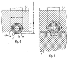
- Fig. 6
- ein elastisch wirksames Klemmelement in seiner Bereitschaftsstellung als in Fig. 3 mit X gekennzeichnete Einzelheit in abgewandelter Ausgestaltung; und
- Fig. 7
- das elastisch wirksame Klemmelement nach Fig. 6 in seiner Klemmstellung, in der eine Targethülse auf den Träger axial aufgeschoben ist.
- Fig. 1
- an embodiment of a target carrier assembly according to the invention in axial section;
- Fig. 2
- the target carrier assembly in side view;
- Fig. 3
- two differently formed regions of a carrier of the target carrier assembly in plan view;
- Fig. 4
- an elastically effective clamping element in its standby position as marked in Figure 3 with X detail.
- Fig. 5
- the elastically active clamping element in its working position, in which a target sleeve is pushed axially onto the carrier;
- Fig. 6
- an elastically effective clamping element in its standby position as in Fig 3 with X marked detail in a modified embodiment; and
- Fig. 7
- the elastically active clamping element of FIG. 6 in its clamping position, in which a target sleeve is pushed axially onto the carrier.
Die Hauptteile der in ihrer Gesamtheit mit 1 bezeichneten
Targetträgeranordnung sind ein Träger 2, der zum Beispiel
durch eine im wesentlichen zylindrische Traghülse 3
gebildet sein kann, und eine Targethülse 4, die mit
geringem Bewegungsspiel auf den Träger 2 aufschiebbar und
darauf durch wenigstens ein Fixierelement in ihrer
Umfangsrichtung und/oder in ihrer Achsrichtung fixiert
ist.The main parts of the designated in their entirety by 1
Target carrier assembly is a carrier 2, for example
by a substantially cylindrical support sleeve. 3
may be formed, and a
Der Träger 2 besteht aus Metall, vorzugsweise Stahl. Er
weist an seinen Enden bei L nur andeutungsweise
dargestellte Befestigungsmittel auf, mit denen er in einem
Drehlager um seine Mittelachse 2a drehbar gelagert ist,
das Teil einer Vorrichtung zum Zerstäuben und Beschichten
(Sputtern) auf einem nicht dargestellten ebenen Substrat
z. B. Floatglas ist. Die Targethülse 3 besteht ebenfalls
aus Metall.The carrier 2 is made of metal, preferably steel. He
has at its ends at L only hinted
shown fastening means, with which he in a
Pivot bearing is rotatably mounted about its central axis 2a,
the part of a device for atomizing and coating
(Sputtering) on a flat substrate, not shown
z. B. float glass is. The
Die axiale Länge L1 des Trägers 2 ist größer als die
axiale Länge L2 der Targethülse 4, wobei Letztere im
mittleren Bereich des Trägers 2 angeordnet ist, so daß
dieser an beiden Enden den Träger 2 überragt.The axial length L1 of the carrier 2 is larger than that
axial length L2 of the
Das durch einen radialen Pfeil verdeutlichte, wenigstens
eine Fixierelement 5 ist ein elastisch wirksames
Klemmelement 6, das beim Ausführungsbeispiel aus
federelastischem Material besteht und eine zwischen dem
Träger 2 und der Targethülse 4 radial wirksame
Klemmspannung ausübt. Dabei kann es an der Targethülse 4
oder vorzugsweise am Träger 2 angeordnet sein, wie es das
Ausführungsbeispiel zeigt. The illustrated by a radial arrow, at least
a fixing element 5 is an elastically
Wie insbesondere aus Fig. 4 und 5 zu entnehmen ist, weist
das Klemmelement 6 einen Klemmschenkel 6a auf, der in
seiner entspannten Freigabestellung gemäß Fig. 4 die
zugehörige Mantelfläche bzw. hohlzylindrische Fuge 7
zwischen dem Träger 2 und der Targethülse 4 überragt. Beim
Montieren der Traghülse 4 durch Aufschieben auf den Träger
2 wird der sich bezüglich der Fuge 7 schräg erstreckende
und eine schräge oder gerundete Einführungskante 6b
bildende Klemmschenkel 6a selbsttätig eingebogen, wobei er
mit seiner dadurch erzeugten elastischen Biegespannung die
radial wirksame elastische Spannung zwischen dem Träger 2
und der Targethülse 4 erzeugt, die die Fixierung
gewährleistet. Es ist vorteilhaft, den Klemmschenkel 6a an
seinem freien Ende mit einem sich entgegengesetzt schräg
oder gerundet erstreckenden Einführungsschenkel 6c
auszubilden, so daß das vorbeschriebene selbsttätige
Einbiegen des Klemmschenkels 6a automatisch beim
Aufschieben der Targethülse 4 wahlweise von der einen oder
von der anderen Seite erfolgt.As can be seen in particular from Fig. 4 and 5, has
the
Der Klemmschenkel 6a ist an seinem Basisende vorzugsweise
einteilig mit einer Klemmelementbasis 6d verbunden, die in
einer Ausnehmung 8 angeordnet und darin fixiert ist, zum
Beispiel durch eine nicht dargestellte Schraube.
Vorzugsweise ist die Klemmelementbasis 6d durch einen mit
dem Klemmschenkel 6a verbundenen Basisschenkel 6e
gebildet, der dadurch in der Ausnehmung 8 fixiert sein
kann, daß seine Länge geringfügig größer bemessen ist, als
die Breite b der Ausnehmung 8, so daß der Basisschenkel 6e
zwischen den Seitenwänden der Ausnehmung 8 durch
Eindrücken festgeklemmt ist.The clamping
Der Einführungsschenkel 6c kann so lang bemessen sein, daß
sein freies Ende in der Klemmstellung an dem das
Klemmelement 6 tragenden Teil, hier am Träger 2 oder am
Grund der Ausnehmung 8 oder am Basisschenkel 6d,
abgestützt ist, wie es Fig. 5 zeigt. Hierdurch läßt sich
die Klemmkraft des Klemmelements 6 vergrößern. Das
Klemmelement 6 ist vorzugsweise durch eine winkelförmige
Feder, insbesondere Blattfeder, gebildet.The
Das Klemmelement 6 kann nicht nur die Fixierfunktion
sondern auch der Wärmeableitung von der Targethülse 4 zum
Träger 2 hin und/oder der elektrischen Leitung zwischen
dem Träger 2 und der Targethülse 4 dienen, wenn es aus
wärmeleitfähigem Material und/oder aus elektrisch
leitfähigem Material besteht.The clamping
Zwecks Vergrößerung der Fixierungskräfte und/oder der
Wärmeableitung und/oder der elektrischen Leitung ist es
vorteilhaft, mehrere Klemmelemente 6 anzuordnen, die
vorzugsweise auf dem gesamten Umfang verteilt sind, so daß
sich eine im wesentlichen auf dem gesamten Umfang
verteilte Funktion ergibt.For the purpose of enlarging the fixation forces and / or the
Heat dissipation and / or the electrical line is it
advantageous to arrange a plurality of clamping
Eine oder mehrere Ausnehmungen 8 können jeweils durch eine
oder mehrere sich in Umfangsrichtung erstreckende
Ringnuten 8a oder eine oder mehrere sich in der
Achsrichtung 2a erstreckende Längsnuten 8b gebildet sein,
wobei jeweils mehrere solcher Nuten 8a, 8b im Bereich der
Targethülse 4 axial oder in Umfangsrichtung etwa
gleichmäßig verteilt angeordnet sein können. Es ist auch
möglich, ein oder mehrere auf dem Umfang verteilt
angeordnete wendelförmige Nuten vorzusehen (nicht
dargestellt).One or more recesses 8 can each by a
or more circumferentially extending
Ring grooves 8a or one or more in the
Axial direction 2a extending longitudinal grooves 8b be formed
in each case a plurality of such grooves 8a, 8b in the region of
Wie es Fig. 1 zeigt, können zur gegebenenfalls
zusätzlichen axialen Fixierung an den Enden der
Targethülse 4 vorzugsweise ringförmige Begrenzungsteile 9
auf dem Träger 2 sitzen und damit lösbar verbunden sein,
zum Beispiel durch andeutungsweise dargestellte Schrauben
11 verschraubt sein, die eine axiale Fixierung der
Targethülse 4 auf dem Träger 2 bewirken.As shown in Fig. 1, the optionally
additional axial fixation at the ends of the
Das Ausführungsbeispiel nach Fig. 6 und 7, bei dem gleiche oder vergleichbare Teile mit gleichen Bezugszeichen versehen sind, zeigt ein Klemmelement oder eine Klemmelementanordnung in abgewandelter Ausgestaltung, die aus mehreren Gründen vorteilhaft ist.The embodiment of FIGS. 6 and 7, wherein the same or similar parts with the same reference numerals are provided, shows a clamping element or a Clamping element arrangement in a modified embodiment, the is advantageous for several reasons.
Ein erster Unterschied zum vorbeschriebenen
Ausführungsbeispiel besteht darin, daß dieses Klemmelement
6 aus so elastisch verformbarem und/oder elastisch
komprimierbarem Material besteht, daß es sich aufgrund
seiner radialen Klemmspannung sowohl an die Targethülse
als auch an den Träger flächig anlegt und dadurch jeweils
eine große Kontaktfläche bildet, an der die elektrische
Leitung und die Wärmeableitung erfolgen.A first difference to the above
Embodiment is that this
Die Wärmeleitfähigkeit und elektrische Leitfähigkeit des
elastisch verformbaren oder elastisch komprimierbaren
Materials des Klemmelements 6 kann durch ein Einbetten von
Partikeln oder Fasern aus elektrisch leitfähigem und
wärmeleitendem Material, insbesondere aus Metall oder
Kohlenstoff erfolgen, wobei das elastische Basismaterial
aus Kunststoff, insbesondere Silikon, bestehen kann.The thermal conductivity and electrical conductivity of the
elastically deformable or elastically compressible
Material of the
Beim Ausführungsbeispiel weist das Klemmelement 6 die Form
eines offenen oder geschlossenen Ringes auf und es
befindet sich in einer ringförmigen Ausnehmung 8, z. B.
eine Ringnut. Dabei ist die radiale Abmessung a des
Klemmelements 6 im radial entspannten Zustand größer als
die radiale Abmessung c der Ausnehmung 8, so daß das
Klemmelement die Ausnehmung 8 überragt und beim
Aufschieben der Targethülse 4 in die Form gemäß Fig. 7
zusammengedrückt wird, in der es unter der radialen
Spannung radial verformt und ggf. auch komprimiert ist.
Die axiale Abmessung der Kontaktfläche K1, mit der das
Klemmelement 6 an der Targethülse 4 anliegt, ist
beträchtlich groß, und zwar insbesondere dann, wenn das
Klemmelement in vorbeschriebener Weise ringförmig
ausgebildet ist, da in diesem Fall die Kontaktfläche K1
sich auch über einen Großteil oder über den gesamten
Umfang erstreckt. In the embodiment, the clamping
Aufgrund der radialen Klemmspannung liegt das Klemmelement
auch an der Grundfläche der Ausnehmung 8 flächig an. Diese
Fläche kann weiter vergrößert werden, wenn sie im axialen
Schnitt gerundet ist. Beim Ausführungsbeispiel ist der
Ausnehmungsgrund konkav gerundet und das Klemmelement 6
entsprechend konvex gerundet. Dabei ist es vorteilhaft,
das Klemmelement 6 mit einer solchen Breite auszubilden,
daß es unter der radialen Klemmspannung auch an den
Seitenwänden der Ausnehmung 8 anliegt, wodurch die
Kontaktfläche K2 weiter vergrößert wird, was erwünscht
ist. Beim Ausführungsbeispiel ist das Klemmelement 6 durch
einen im Querschnitt runden Ring gebildet, dessen
Innendurchmesser d dem Innendurchmesser des Ringnutgrundes
entspricht oder etwas kleiner bemessen ist, so daß der so
gebildete Klemmring mit einer elastischen Spannung am
Ringnutgrund anliegt. Aufgrund der Ringform ist das
Klemmelement 6 auch unverlierbar gehalten.Due to the radial clamping voltage is the clamping element
also on the base of the recess 8 flat. These
Surface can be further enlarged when in axial
Cut is rounded. In the embodiment of the
Ausnehmungsgrund rounded concave and the clamping element. 6
correspondingly convex rounded. It is advantageous
form the
Beim Ausführungsbeispiel ist das Klemmelement 6 ein
Hohlkörper mit einen zentralen Hohlraum 6f. Wenn das
Klemmelement 6 ein Klemmring ist, kann es durch einen
endlosen Schlauch gebildet sein, insbesondere einen
dickwandigen Schlauch, dessen Wanddicke etwa ein Viertel
seiner Querschnittsabmessung betragen kann.In the embodiment, the clamping
Die zumindest außen gerundete Form des Klemmelements 6 ist
vorteilhaft, weil sie beidseitig Einführungsflächen 6b, 6c
bildet, die beim Aufschieben der Targethülse bzw.
Einschieben des Trägers 2 selbsttätig ein Verdrängen des
Klemmelements 6 in die Ausnehmung 8 ermöglichen.The at least externally rounded shape of the
Die Elastizität des Klemmelements 6 ist bei dessen
Ausbildung in geschlossener Ringform so groß, daß es zu
seiner Montage bzw. Demontage über den Außendurchmesser
des Trägers 2 gestreckt werden kann und sich in der
Ringnut 8a selbsttätig zum Nutgrund kontrahiert,
vorzugsweise so weit, daß es mit einer
Kontraktionsspannung am Nutgrund anliegt.The elasticity of the
Claims (16)
- Target support assembly (1), comprising a support sleeve (2) on which is arranged a target lining that is formed by a target sleeve (4) that is slid on to the support sleeve (2) or into which the support sleeve (4) is slid, at least one clamping element (6) being arranged to be clampingly effective between the support sleeve (2) and the target sleeve (4),
characterised in that a plurality of elastically active clamping elements (6) are provided which are distributed around the circumference and are formed in each case by a spring, and which are arranged in a recess (8) in the internal cylindrical surface of the target sleeve (4) or in the external cylindrical surface of the support sleeve (2) in a captive manner on the part carrying them (support sleeve or target sleeve) and press elastically against the external cylindrical surface or internal cylindrical surface located opposite said clamping elements (6). - Target support assembly according to claim 1,
characterised in that the clamping elements (6) have rounded or oblique insertion edges (6b, 6c) on both sides facing in the axial direction. - Target support assembly according to claim 1 or 2,
characterised in that to exert their clamping pressure the clamping elements (6) have in each case a clamping arm (6a) that exerts the clamping pressure with its free end portion. - Target support assembly according to claim 3,
characterised in that an insertion segment (6c) is arranged at the free end of the clamping arm (6a) and forms an angled or rounded roof-shaped element with the clamping arm (6a). - Target support assembly according to claim 4,
characterised in that the free end of the insertion segment (6c) is supported against the clamping stress in the clamping position. - Target support assembly according to any one of the preceding claims,
characterised in that the clamping elements (6) are wedged between the side walls of a recess (8). - Target support assembly according to any one of the preceding claims 3 to 6,
characterised in that the clamping elements (6) are in each case formed by an angled spring, in particular an angled leaf spring, comprising the clamping arm (6a) and a base arm (6e). - Target support assembly according to claim 7,
characterised in that the base arm (6e) is wedged between the side walls of the recess (8). - Target support assembly according to claim 8,
characterised in that one or more recesses (8) is/are formed as grooves (8a, 8b) extending in the circumferential or axial direction or helically. - Target support assembly according to claim 9,
characterised in that the groove or grooves extending in the circumferential direction is/are formed in each case by an annular groove. - Target support assembly according to any one of the preceding claims,
characterised in that the clamping elements (6) are in each case made of elastically deformable and/or elastically compressible material. - Target support assembly according to claim 11,
characterised in that the clamping elements (6) are made of synthetic material and in that particles or fibres of electrically and/or thermally conductive material are embedded in the material of the clamping elements (6). - Target support assembly according to claim 3 and either of claims 15 and 16,
characterised in that the clamping elements (6) have, at least in the area of an opening of the recess (8), a shape that is convex, in particular rounded, viewed transversely to the axial direction of the support. - Target support assembly according to claim 13,
characterised in that the clamping elements (6) and the recess (8) have an annular configuration. - Target support assembly according to claim 14,
characterised in that the clamping elements (6) have in each case, at least on their inner side, a convexly rounded cross-sectional form and the base of the recess is preferably rounded correspondingly. - Target support assembly according to any one of the preceding claims,
characterised in that the length (L1) of the support sleeve (2) is greater than the length (L2) of the target sleeve (4) and at least one annular limiting part (9) is fixed detachably on the support sleeve (2) at one or both ends of the target sleeve (4).
Applications Claiming Priority (3)
| Application Number | Priority Date | Filing Date | Title |
|---|---|---|---|
| DE10231203A DE10231203B4 (en) | 2002-07-10 | 2002-07-10 | Target support assembly |
| DE10231203 | 2002-07-10 | ||
| PCT/EP2003/006518 WO2004007791A1 (en) | 2002-07-10 | 2003-06-20 | Target support assembly |
Publications (2)
| Publication Number | Publication Date |
|---|---|
| EP1518006A1 EP1518006A1 (en) | 2005-03-30 |
| EP1518006B1 true EP1518006B1 (en) | 2005-10-05 |
Family
ID=30009885
Family Applications (1)
| Application Number | Title | Priority Date | Filing Date |
|---|---|---|---|
| EP03763647A Expired - Lifetime EP1518006B1 (en) | 2002-07-10 | 2003-06-20 | Target support assembly |
Country Status (4)
| Country | Link |
|---|---|
| US (1) | US7811429B2 (en) |
| EP (1) | EP1518006B1 (en) |
| DE (2) | DE10231203B4 (en) |
| WO (1) | WO2004007791A1 (en) |
Families Citing this family (25)
| Publication number | Priority date | Publication date | Assignee | Title |
|---|---|---|---|---|
| KR100867620B1 (en) | 2005-05-25 | 2008-11-10 | 삼성전자주식회사 | Apparatus and method for selecting user of sdma on mimo system |
| EP1752556B1 (en) | 2005-08-02 | 2007-10-31 | Applied Materials GmbH & Co. KG | Tubular cathode for use in sputtering. |
| DE102006009749A1 (en) * | 2006-03-02 | 2007-09-06 | FNE Forschungsinstitut für Nichteisen-Metalle Freiberg GmbH | target arrangement |
| US20140021044A1 (en) * | 2006-10-02 | 2014-01-23 | Thermal Conductive Bonding, Inc. | Elastomer Bonded Rotary Sputtering Target |
| US20080078268A1 (en) | 2006-10-03 | 2008-04-03 | H.C. Starck Inc. | Process for preparing metal powders having low oxygen content, powders so-produced and uses thereof |
| US20080145688A1 (en) | 2006-12-13 | 2008-06-19 | H.C. Starck Inc. | Method of joining tantalum clade steel structures |
| US8197894B2 (en) | 2007-05-04 | 2012-06-12 | H.C. Starck Gmbh | Methods of forming sputtering targets |
| DE102007044651B4 (en) | 2007-09-18 | 2011-07-21 | W.C. Heraeus GmbH, 63450 | Pipe sputtering target with grave-shaped structured outer surface of the support tube and method for its preparation |
| US8246903B2 (en) | 2008-09-09 | 2012-08-21 | H.C. Starck Inc. | Dynamic dehydriding of refractory metal powders |
| SG195563A1 (en) * | 2008-10-24 | 2013-12-30 | Applied Materials Inc | Rotatable sputter target base, rotatable sputter target, coating installation, method of producing a rotatable sputter target, target base connection means, and method of connecting a rotatable target base device for sputtering installations to a target base support |
| TW201028491A (en) * | 2008-10-24 | 2010-08-01 | Applied Materials Inc | Rotatable sputter target backing cylinder, rotatable sputter target, method of producing a rotatable sputter target, and coating installation |
| EP2180500A1 (en) * | 2008-10-24 | 2010-04-28 | Applied Materials, Inc. | Rotatable sputter target backing cylinder, rotatable sputter target, methods of producing and restoring a rotatable sputter target, and coating installation |
| EP2180501A1 (en) * | 2008-10-24 | 2010-04-28 | Applied Materials, Inc. | Rotatable sputter target base, rotatable sputter target, coating installation, method of producing a rotatable sputter target, target base connection means, and method of connecting a rotatable target base device for sputtering installations to a target base support |
| US20100101946A1 (en) * | 2008-10-24 | 2010-04-29 | Applied Materials, Inc. | Rotatable sputter target backing cylinder, rotatable sputter target, methods of producing and restoring a rotatable sputter target, and coating installation |
| EP2276055A1 (en) * | 2009-07-13 | 2011-01-19 | Applied Materials, Inc. | Target backing tube, cylindrical target, and cylindrical target assembly |
| DE202009014959U1 (en) * | 2009-10-23 | 2010-10-21 | Sindlhauser Materials Gmbh | Sputtertargetanordnung |
| EP2365515A1 (en) * | 2010-03-09 | 2011-09-14 | Applied Materials, Inc. | Rotatable target, backing tube, sputtering installation and method for producing a rotatable target |
| TWI393796B (en) * | 2010-06-02 | 2013-04-21 | Solar Applied Mat Tech Corp | Hollow target assembly |
| RU2013103041A (en) * | 2010-07-12 | 2014-08-20 | Мэтиреон Эдвансд Мэтириэлз Текнолоджиз Энд Сервисез Инк. | ROTARY TARGET CONNECTOR ASSEMBLY |
| CN102338598B (en) * | 2010-07-19 | 2014-02-19 | 光洋应用材料科技股份有限公司 | Hollow target material component |
| EP2420589B1 (en) * | 2010-08-19 | 2013-03-20 | Solar Applied Materials Technology Corp. | Hollow target assembly |
| US8734896B2 (en) | 2011-09-29 | 2014-05-27 | H.C. Starck Inc. | Methods of manufacturing high-strength large-area sputtering targets |
| DE102013100383B4 (en) * | 2013-01-15 | 2019-12-05 | VON ARDENNE Asset GmbH & Co. KG | magnetron |
| DE102013100382B4 (en) * | 2013-01-15 | 2019-12-05 | VON ARDENNE Asset GmbH & Co. KG | magnetron |
| US9328410B2 (en) | 2013-10-25 | 2016-05-03 | First Solar, Inc. | Physical vapor deposition tile arrangement and physical vapor deposition arrangement |
Family Cites Families (12)
| Publication number | Priority date | Publication date | Assignee | Title |
|---|---|---|---|---|
| US4356073A (en) | 1981-02-12 | 1982-10-26 | Shatterproof Glass Corporation | Magnetron cathode sputtering apparatus |
| JPH01193463A (en) * | 1988-01-29 | 1989-08-03 | Matsushita Electric Ind Co Ltd | Vacuum seal structure of vacuum working device |
| US4851798A (en) | 1988-03-31 | 1989-07-25 | Rca Licensing Corporation | Unitary tuning structure |
| US4820397A (en) * | 1988-04-04 | 1989-04-11 | Tosoh Smd, Inc. | Quick change sputter target assembly |
| US5147521A (en) | 1991-05-20 | 1992-09-15 | Tosoh Smd, Inc. | Quick change sputter target assembly |
| US5487822A (en) * | 1993-11-24 | 1996-01-30 | Applied Materials, Inc. | Integrated sputtering target assembly |
| DE4414470A1 (en) * | 1994-04-26 | 1995-11-02 | Leybold Ag | Atomizer cathode |
| US5591314A (en) * | 1995-10-27 | 1997-01-07 | Morgan; Steven V. | Apparatus for affixing a rotating cylindrical magnetron target to a spindle |
| TW555874B (en) * | 2000-09-08 | 2003-10-01 | Asahi Glass Co Ltd | Cylindrical target and its production method |
| JP4614037B2 (en) * | 2000-09-08 | 2011-01-19 | Agcセラミックス株式会社 | Cylindrical target |
| US6409897B1 (en) * | 2000-09-20 | 2002-06-25 | Poco Graphite, Inc. | Rotatable sputter target |
| DE10102493B4 (en) * | 2001-01-19 | 2007-07-12 | W.C. Heraeus Gmbh | Tubular target and method of making such a target |
-
2002
- 2002-07-10 DE DE10231203A patent/DE10231203B4/en not_active Expired - Lifetime
-
2003
- 2003-06-20 WO PCT/EP2003/006518 patent/WO2004007791A1/en active IP Right Grant
- 2003-06-20 EP EP03763647A patent/EP1518006B1/en not_active Expired - Lifetime
- 2003-06-20 US US10/520,755 patent/US7811429B2/en active Active
- 2003-06-20 DE DE50301326T patent/DE50301326D1/en not_active Expired - Lifetime
Also Published As
| Publication number | Publication date |
|---|---|
| US7811429B2 (en) | 2010-10-12 |
| EP1518006A1 (en) | 2005-03-30 |
| DE10231203A1 (en) | 2004-02-05 |
| WO2004007791A1 (en) | 2004-01-22 |
| US20050224342A1 (en) | 2005-10-13 |
| DE10231203B4 (en) | 2009-09-10 |
| DE50301326D1 (en) | 2006-02-16 |
Similar Documents
| Publication | Publication Date | Title |
|---|---|---|
| EP1518006B1 (en) | Target support assembly | |
| EP0505719B1 (en) | Ball joint | |
| DE2819744C2 (en) | Hinge, in particular eyeglass hinge | |
| EP0295319B1 (en) | Engraved cylinder composed of a core and a detachable sleeve | |
| EP1211137B1 (en) | Connecting element | |
| EP0214192A1 (en) | Brush seal. | |
| EP0745829B1 (en) | Measuring cable-transducer having a shell housing | |
| DE19929391B4 (en) | brake disc | |
| DE202005005762U1 (en) | Bearing bushing comprises protrusions which protrude radially from a housing on the outer side of the housing on the holding region and can be deformed in the radial direction | |
| EP3228891B1 (en) | Device and method for resetting a bearing shell which has slid out of a recess on a shaft | |
| EP1548483B1 (en) | Microscope objective with axially adjustable corrective mounts | |
| DE4112133A1 (en) | Lever mechanism, esp. foot lever mechanism for motor vehicle - has bearing bolt with fixed arm engaging bearing plate | |
| EP2083237B1 (en) | Muzzle bundle for a handgun | |
| DE2548504A1 (en) | DEVICE FOR FASTENING A ROTARY KNOB TO A SHAFT | |
| DE1912976B2 (en) | Rolling bearings for longitudinal movements with a linear bushing | |
| DE19721611C2 (en) | vacuum chamber | |
| EP0269666A1 (en) | Connection system. | |
| DE10006248A1 (en) | Fluid container with removable floor | |
| DE3014600C2 (en) | Connection fitting for an insulator rod made of glass fiber reinforced plastic | |
| DE3535778A1 (en) | Vibration damper for electrical overhead lines | |
| DE2516142C3 (en) | Tilt and turn joint for lights | |
| WO1980001621A1 (en) | High-voltage composite insulator | |
| DE7712593U1 (en) | Tappet switchgear | |
| DE10228137B4 (en) | Fixing device and screw connector for cable ladder with such a fixing device | |
| DE102007044496A1 (en) | Lubricant scraper and plain bearing arrangement with such a lubricant scraper |
Legal Events
| Date | Code | Title | Description |
|---|---|---|---|
| PUAI | Public reference made under article 153(3) epc to a published international application that has entered the european phase |
Free format text: ORIGINAL CODE: 0009012 |
|
| 17P | Request for examination filed |
Effective date: 20041206 |
|
| AK | Designated contracting states |
Kind code of ref document: A1 Designated state(s): AT BE BG CH CY CZ DE DK EE ES FI FR GB GR HU IE IT LI LU MC NL PT RO SE SI SK TR |
|
| GRAP | Despatch of communication of intention to grant a patent |
Free format text: ORIGINAL CODE: EPIDOSNIGR1 |
|
| RBV | Designated contracting states (corrected) |
Designated state(s): DE FR GB |
|
| GRAS | Grant fee paid |
Free format text: ORIGINAL CODE: EPIDOSNIGR3 |
|
| GRAA | (expected) grant |
Free format text: ORIGINAL CODE: 0009210 |
|
| AK | Designated contracting states |
Kind code of ref document: B1 Designated state(s): DE FR GB |
|
| REG | Reference to a national code |
Ref country code: GB Ref legal event code: FG4D Free format text: NOT ENGLISH |
|
| GBT | Gb: translation of ep patent filed (gb section 77(6)(a)/1977) |
Effective date: 20051005 |
|
| REF | Corresponds to: |
Ref document number: 50301326 Country of ref document: DE Date of ref document: 20060216 Kind code of ref document: P |
|
| ET | Fr: translation filed | ||
| PLBE | No opposition filed within time limit |
Free format text: ORIGINAL CODE: 0009261 |
|
| STAA | Information on the status of an ep patent application or granted ep patent |
Free format text: STATUS: NO OPPOSITION FILED WITHIN TIME LIMIT |
|
| 26N | No opposition filed |
Effective date: 20060706 |
|
| REG | Reference to a national code |
Ref country code: FR Ref legal event code: PLFP Year of fee payment: 13 |
|
| REG | Reference to a national code |
Ref country code: FR Ref legal event code: PLFP Year of fee payment: 14 |
|
| REG | Reference to a national code |
Ref country code: FR Ref legal event code: PLFP Year of fee payment: 15 |
|
| REG | Reference to a national code |
Ref country code: FR Ref legal event code: PLFP Year of fee payment: 16 |
|
| PGFP | Annual fee paid to national office [announced via postgrant information from national office to epo] |
Ref country code: GB Payment date: 20220623 Year of fee payment: 20 |
|
| PGFP | Annual fee paid to national office [announced via postgrant information from national office to epo] |
Ref country code: FR Payment date: 20220622 Year of fee payment: 20 |
|
| PGFP | Annual fee paid to national office [announced via postgrant information from national office to epo] |
Ref country code: DE Payment date: 20220627 Year of fee payment: 20 |
|
| REG | Reference to a national code |
Ref country code: DE Ref legal event code: R071 Ref document number: 50301326 Country of ref document: DE |
|
| REG | Reference to a national code |
Ref country code: GB Ref legal event code: PE20 Expiry date: 20230619 |
|
| PG25 | Lapsed in a contracting state [announced via postgrant information from national office to epo] |
Ref country code: GB Free format text: LAPSE BECAUSE OF EXPIRATION OF PROTECTION Effective date: 20230619 |