EP1517836B1 - Strapping device - Google Patents
Strapping device Download PDFInfo
- Publication number
- EP1517836B1 EP1517836B1 EP03720077A EP03720077A EP1517836B1 EP 1517836 B1 EP1517836 B1 EP 1517836B1 EP 03720077 A EP03720077 A EP 03720077A EP 03720077 A EP03720077 A EP 03720077A EP 1517836 B1 EP1517836 B1 EP 1517836B1
- Authority
- EP
- European Patent Office
- Prior art keywords
- strapping
- loop
- channel
- guide
- strapped
- Prior art date
- Legal status (The legal status is an assumption and is not a legal conclusion. Google has not performed a legal analysis and makes no representation as to the accuracy of the status listed.)
- Expired - Lifetime
Links
- 238000009434 installation Methods 0.000 claims abstract 23
- 238000003825 pressing Methods 0.000 claims description 27
- 230000000630 rising effect Effects 0.000 claims description 6
- 238000000034 method Methods 0.000 claims description 5
- 210000003127 knee Anatomy 0.000 claims description 3
- 238000007599 discharging Methods 0.000 abstract 1
- 239000000463 material Substances 0.000 description 41
- 239000000969 carrier Substances 0.000 description 3
- 238000004904 shortening Methods 0.000 description 3
- 238000003466 welding Methods 0.000 description 3
- 230000006835 compression Effects 0.000 description 1
- 238000007906 compression Methods 0.000 description 1
- 230000003247 decreasing effect Effects 0.000 description 1
- 238000004519 manufacturing process Methods 0.000 description 1
- 238000012536 packaging technology Methods 0.000 description 1
- 230000000717 retained effect Effects 0.000 description 1
- 239000007787 solid Substances 0.000 description 1
- 230000001360 synchronised effect Effects 0.000 description 1
Images


Classifications
-
- B—PERFORMING OPERATIONS; TRANSPORTING
- B65—CONVEYING; PACKING; STORING; HANDLING THIN OR FILAMENTARY MATERIAL
- B65B—MACHINES, APPARATUS OR DEVICES FOR, OR METHODS OF, PACKAGING ARTICLES OR MATERIALS; UNPACKING
- B65B27/00—Bundling particular articles presenting special problems using string, wire, or narrow tape or band; Baling fibrous material, e.g. peat, not otherwise provided for
- B65B27/08—Bundling paper sheets, envelopes, bags, newspapers, or other thin flat articles
-
- B—PERFORMING OPERATIONS; TRANSPORTING
- B65—CONVEYING; PACKING; STORING; HANDLING THIN OR FILAMENTARY MATERIAL
- B65B—MACHINES, APPARATUS OR DEVICES FOR, OR METHODS OF, PACKAGING ARTICLES OR MATERIALS; UNPACKING
- B65B13/00—Bundling articles
- B65B13/02—Applying and securing binding material around articles or groups of articles, e.g. using strings, wires, strips, bands or tapes
- B65B13/04—Applying and securing binding material around articles or groups of articles, e.g. using strings, wires, strips, bands or tapes with means for guiding the binding material around the articles prior to severing from supply
- B65B13/06—Stationary ducts or channels
-
- B—PERFORMING OPERATIONS; TRANSPORTING
- B65—CONVEYING; PACKING; STORING; HANDLING THIN OR FILAMENTARY MATERIAL
- B65B—MACHINES, APPARATUS OR DEVICES FOR, OR METHODS OF, PACKAGING ARTICLES OR MATERIALS; UNPACKING
- B65B27/00—Bundling particular articles presenting special problems using string, wire, or narrow tape or band; Baling fibrous material, e.g. peat, not otherwise provided for
- B65B27/08—Bundling paper sheets, envelopes, bags, newspapers, or other thin flat articles
- B65B27/086—Bundling paper sheets, envelopes, bags, newspapers, or other thin flat articles using more than one tie, e.g. cross-ties
Definitions
- the strapping device like the strapping devices according to EP-1207107 and US-5078057 in the strapping position on a closing area under the support surface in which a loop channel begins and ends, in which the strapping material for looping is fed into the loop channel in which the the loop channel guided, free loop end is held, in which the strapping material is withdrawn to reduce the tension and the loop of the loop channel and in which closed the strapping and separated from further supplied strapping material becomes.
- the loop channel which is substantially formed as a groove in the support surface, runs in two opposite directions from the Schliess Scheme starting from the Umreifungsposition and closes around the Umreifungsposition (or to the largest floor plan of an object to be strapped) around.
- the closing area is located, for example, in the center under an object to be strapped and, for longitudinal strapping, the beginning and end of the loop channel run parallel to the conveying direction.
- a longitudinal strapping using the device according to the invention is carried out in the following manner.
- the groove-shaped loop channel for example, by inserting a free end of the strapping material from the closing area forth until the closing area where the loop end is held, presented a loop.
- means may also be provided for pulling the strapping material into the loop channel.
- FIG. 1 shows the strapping position of an exemplary embodiment of the strapping device according to the invention.
- This is equipped for a central L Lucassumreifung an object 1, which is conveyed in a substantially horizontal conveying direction F on a support surface 2 in the Umreifungsposition and after strapping back in the conveying direction F from the Umreifungsposition addition.
- the closing area 3 is set in a corresponding recess of the support surface 2 below the level of the support surface. From the closing area 3 extends parallel to the conveying direction F in both directions a recessed into the support surface 2, groove-shaped loop channel 4, which closes on one side to the floor plan 5 of a largest object to be strapped around.
- the loop guide 10 can also have a plurality of slide rails instead of the two slide rails 10.1 and 10.2 shown in FIG. 1, or it can be designed as a single, flat element.
- the loop guide 10 rises within the loop channel 4 and on one side of the strapping position from the support surface 2 and arches over or against the strapping position, such that its upper end is positioned approximately above the closure region 3, for example.
- the outside of the loop guide 10 is equipped for a sliding movement of the strapping material.
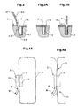
- Figures 4A and 4B show a plan view of the support surface two variants, according to which a band-shaped strapping material 6 can be arranged in the loop channel and through the closing area. It is ever a belt loop shown and very schematically the closing area 3, in which the strapping material 6 fed into the loop channel (direction Z), the free end 7 held and the strapping material 6 is withdrawn from the loop channel (direction R) is. The loop channel is not shown.
- the rotatability of the tape holder may be active or passive depending on the stiffness of the strapping.
- the rotatable band holder advantageously has elastic return means, by which the band holder, as soon as the strapping band is removed therefrom, is rotated back into the starting position.
- the pressing elements 42 can be lowered by means of a common drive 41 onto the object 1 to be strapped.
- the drive 41 is realized, for example, as a chain hoist 43 arranged below the bearing surface 2 with traverses 44 coupled thereto and with a respective vertical carrier 45 arranged laterally of the strapping position for each pressing element 42.
- the pressing members 42 may be formed as simple relative to the vertical supports 45 stationarily arranged pressing plates.
- they are, as shown in Figure 7, configured as angled toggle 46, which are arranged tiltable about an axis 47 in the region of the upper ends of the vertical support 45 and each one extending over the Umreifungsposition, pressing part 46.1 and a have laterally extending part 46.2.
- the knee lever part 46.2 is distanced for example by means of spring 48 from the vertical support 45, such that the toggle lever part 46.1 is directed at uncompressed spring 48 from the axis of rotation 47 from below.
- the pressing elements 42 can simultaneously also assume a guiding function for a loop released from the loop guide 10.
- freely rotatable rollers 50 are arranged at the two ends of the toggle parts 46.1 and 46.2 and optionally also between them, of which a guide band 51, whose both ends are fixed to stationary parts of the device is held in a predetermined position.
- Each of the four pressing elements 42 is associated with at least one such guide band 51.
- the guide bands 51 extend on one side of the Lfitsumreifungsebene L from the loop channel 30 for Querumreifung on the other side of the Lnaturereifungsebene L from the end of the loop guide 10 to the end of the pressing toggle 46.1, from there to the end of the side toggle 46.2 and from there against the supporting surface.
- the guide bands 51 are optionally held slightly stretched with suitable means, not shown.
Landscapes
- Engineering & Computer Science (AREA)
- Mechanical Engineering (AREA)
- Basic Packing Technique (AREA)
- Saccharide Compounds (AREA)
- Finger-Pressure Massage (AREA)
- Thermotherapy And Cooling Therapy Devices (AREA)
- Microwave Tubes (AREA)
Abstract
Description
Die Erfindung liegt im Bereiche der Verpackungstechnik und bezieht sich auf eine Umreifungsvorrichtung nach dem Oberbegriff des unabhängigen Patentanspruchs. Die Umreifungsvorrichtung dient zum Umreifen von Objekten, insbesondere von im wesentlichen quaderförmigen Objekten, z.B. von Stapeln von Druckprodukten wie Zeitungen, Zeitschriften etc. und sie dient insbesondere für eine im wesentlichen gleichzeitige Umreifung in zwei aufeinander senkrecht stehenden Richtungen (Kreuzumreifung). Zur Umreifung wird ein Umreifungsmaterial verwendet, das die Form eines Bandes (Umreifungsband) oder die Form einer Schnur oder eines Drahtes haben kann und das vorteilhafterweise derart steif ist, dass es geschoben bewegt werden kann.The invention is in the field of packaging technology and relates to a strapping device according to the preamble of the independent claim. The strapping device is used for strapping objects, in particular substantially cuboidal objects, e.g. of stacks of printed products such as newspapers, magazines, etc., and it serves in particular for a substantially simultaneous strapping in two mutually perpendicular directions (cross strapping). For strapping, use is made of a strapping material, which may be in the form of a band (strapping) or the form of a cord or wire, and which is advantageously stiff enough to be slidably moved.
Für eine automatisch durchgeführte solche Umreifung wird ein zu umreifendes Objekt auf einer Auflagefläche in eine Umreifungsposition gefördert, in der Umreifungsposition positioniert und umreift und dann von der Umreifungsposition weggefördert. Üblicherweise wird das Umreifungsmaterial, das beispielsweise von einer Vorratsspule von unten gegen die Umreifungsposition zugeführt wird, im Bereiche der Umreifungsposition zu einer Schlaufe geformt, die grösser ist als die zu erstellende Umreifung und die eine Position hat aus der sie um das zu umreifende Objekt legbar ist. Diese Schlaufe wird dann durch Zurückziehen des Bandes um das zu umreifende Objekt gelegt, angespannt, üblicherweise unterhalb des Objektes geschlossen und von weiter zugeführtem Umreifungsmaterial abgetrennt.For an automatically performed such strapping an object to be strapped is supported on a support surface in a strapping position, positioned in the strapping position and strapped and then transported away from the strapping position. Usually, the strapping material, which is supplied, for example, from a supply spool from below against the strapping position, in the region of the strapping position is formed into a loop which is larger than the strapping to be created and which has a position from which it can be laid around the object to be strapped , This loop is then placed by pulling the tape around the object to be strapped, strained, usually closed below the object and separated from further supplied strapping material.
Das Vorlegen der Schlaufe für eine Längsumreifung (Umreifungsrichtung parallel zur Förderrichtung) ist weniger einfach realisierbar als das Vorlegen einer Schlaufe für eine Querumreifung (Umreifungsrichtung quer zur Förderrichtung), denn die Längsschlaufe überspannt in ihrer endgültigen Position den Zuführungsweg des zu umreifenden Objektes, kann also bei der Zuförderung des Objektes diese Position nicht einnehmen. Verschiedene Methoden zum Vorlegen einer Längsschlaufe derart, dass das zu umreifende Objekt trotzdem nach oder vorteilhafterweise während dem Vorlegen der Schlaufe in die Umreifungsposition gefördert werden kann, gehören zum Stande der Technik.The presentation of the loop for a Längsumreifung (strapping parallel to the conveying direction) is less feasible than the presentation of a loop for a Querierreifung (strapping transversely to the conveying direction), because the longitudinal loop spans in its final position, the feed path of the object to be strapped, so at the conveyance of the object does not occupy this position. Various methods for presenting a longitudinal loop such that the object to be strapped can still be promoted after or advantageously during the presentation of the loop in the Umreifungsposition belong to the prior art.
Eine derartige Methode ist beschrieben in der Publikation EP-1207107, in der für das Vorlegen der Schlaufe ein in der Auflagefläche integrierter, nutförmiger Schlaufenkanal vorgeschlagen wird. Die Schlaufe wird also unter der Auflagefläche in einer horizontalen Ausrichtung vorgelegt, wo sie die Zuförderung des zu umreifenden Objektes nicht stört. Sobald das zu umreifende Objekt in der Umreifungsposition positioniert ist, wird die Schlaufe mittels Schlaufenbewegungsmittel aus dem Schlaufenkanal gehoben und in eine senkrechte Position gebracht, derart, dass sie rund um das zu umreifende Objekt führt. Von dieser Position wird die Schlaufe durch Zurückziehen des Umreifungsmaterials an das Objekt angelegt und gespannt. Als Schlaufenbewegungsmittel werden Greifer vorgeschlagen, die vor der Schlaufenbewegung im Bereiche des nutförmigen Kanals positioniert sind und die für die Schlaufenbewegung zusammen mit der Schlaufe entlang geeigneter Schienen seitlich vom zu umreifenden Objekt hoch und über das zu umreifende Objekt gefahren werden. Die Greifer stellen sehr kleine zu beschleunigende Teile dar und können deshalb sehr schnell bewegt werden.Such a method is described in the publication EP-1207107, in which a groove-shaped loop channel integrated in the bearing surface is proposed for the presentation of the loop. The loop is thus submitted under the support surface in a horizontal orientation, where it does not interfere with the conveyance of the object to be strapped. Once the object to be strapped is positioned in the strapping position, the loop is lifted out of the loop channel by means of loop movement means and brought into a vertical position such that it leads around the object to be strapped. From this position, the loop is created by tightening the strapping material against the object and tensioned. As a loop moving means grippers are proposed, which are positioned before the loop movement in the regions of the groove-shaped channel and the loop movement along with the loop along suitable rails to the side of the object to be hooped and driven over the object to be strapped. The grippers are very small parts to be accelerated and can therefore be moved very quickly.
Eine weitere Methode wird in der Publikation US-5078057 (oder DE-4100276, Signode Corp.) beschrieben. Diese Publikation offenbart eine im wesentlichen gleichzeitige Längs- und Querumreifung (Kreuzumreifung). Für beide Umreifungen sind je ein Schlaufenkanal vorgesehen, wobei der Längskanal sich seitlich vom zu umreifenden Objekt einen Bogen bildend über die Auflagefläche erhebt und der obere Teil des Bogens sich über ein in der Umreifungsposition positioniertes, zu umreifendes Objekt wölbt, derart, dass der Bogen den Zuführungsweg für das Objekt nicht versperrt und die vorgelegte Schlaufe trotzdem teilweise über dem für die Umreifung positionierten Objekt verläuft. Diese Form des Längskanales macht es mindestens für ein bandförmiges Umreifungsmaterial notwendig, dass der Schlaufenkanal nicht nur gebogen sondern auch verwunden ist, also ein in der Herstellung recht aufwendiges Maschinenteil darstellt.Another method is described in publication US-5078057 (or DE-4100276, Signode Corp.). This publication discloses a substantially simultaneous longitudinal and Querierreifung (cross strapping). For both strappings are ever a loop channel is provided, wherein the longitudinal channel arches laterally from the object to be strapped over the support surface and the upper part of the arch curves over an object positioned to be strapped in the strapping position, such that the sheet does not provide the delivery path for the object obstructed and the loop presented anyway partially extends over the object positioned for strapping. This shape of the longitudinal channel makes it necessary, at least for a band-shaped strapping material, that the loop channel is not only bent but also twisted, that is to say a machine part that is rather complicated to manufacture.
Die Erfindung stellt sich nun die Aufgabe, eine Umreifungsvorrichtung zu schaffen, mit der in einfachster Weise, mit einem Minimum an sich bewegenden Teilen und trotzdem mit kurzen Zykluszeiten Umreifungen mittels vorgelegter Schlaufe des Umreifungsmaterials durchführbar sind, insbesondere Längsumreifungen, die auch in einfacher Weise mit einer im wesentlichen gleichzeitigen Querumreifung kombinierbar sind.The invention now has the object to provide a strapping, with the simplest way, with a minimum of moving parts and still with short cycle times strapping by means of laid loop of the strapping material are feasible, in particular Längsumreifungen, in a simple manner with a essentially simultaneous Querumreifung can be combined.
Diese Aufgabe wird gelöst durch die Umreifungsvorrichtung, wie sie in den Patentansprüchen definiert ist.This object is achieved by the strapping device as defined in the patent claims.
Die erfindungsgemässe Umreifungsvorrichtung weist wie die Umreifungsvorrichtungen gemäss EP-1207107 und US-5078057 in der Umreifungsposition einen Schliessbereich unter der Auflagefläche auf, in dem ein Schlaufenkanal anfängt und endet, in dem das Umreifungsmaterial für die Schlaufenbildung in den Schlaufenkanal zugeführt wird, in dem das durch den Schlaufenkanal geführte, freie Schlaufenende festgehalten wird, in dem das Umreifungsmaterial zur Verkleinerung und Spannung der Schlaufe aus dem Schlaufenkanal zurückgezogen wird und in dem die Umreifung geschlossen und von weiter zugeführtem Umreifungsmaterial abgetrennt wird. Der Schlaufenkanal, der im wesentlichen als Nut in der Auflagefläche ausgebildet ist, läuft in zwei einander entgegengesetzten Richtungen vom Schliessbereich ausgehend aus der Umreifungsposition hinaus und schliesst sich um die Umreifungsposition (bzw. um den grössten Grundriss eines zu umreifenden Objekts) herum. Der Schliessbereich liegt beispielsweise mittig unter einem zu umreifenden Objekt und für eine Längsumreifung verlaufen Anfang und Ende des Schlaufenkanals parallel zur Förderrichtung.The strapping device according to the invention, like the strapping devices according to EP-1207107 and US-5078057 in the strapping position on a closing area under the support surface in which a loop channel begins and ends, in which the strapping material for looping is fed into the loop channel in which the the loop channel guided, free loop end is held, in which the strapping material is withdrawn to reduce the tension and the loop of the loop channel and in which closed the strapping and separated from further supplied strapping material becomes. The loop channel, which is substantially formed as a groove in the support surface, runs in two opposite directions from the Schliessbereich starting from the Umreifungsposition and closes around the Umreifungsposition (or to the largest floor plan of an object to be strapped) around. The closing area is located, for example, in the center under an object to be strapped and, for longitudinal strapping, the beginning and end of the loop channel run parallel to the conveying direction.
Anders als die Umreifungsvorrichtung gemäss EP-1207107 weist die erfindungsgemässe Umreifungsvorrichtung eine (mindestens während der Umreifung) stationäre Schlaufenführung auf, die sich innerhalb des Schlaufenkanals und auf einer Seite von einem in der Umreifungsposition positionierten, zu umreifenden Objekts aus der Auflagefläche erhebt und sich je nach der Richtung der Zuführung des zu umreifenden Objektes über oder gegen die Umreifungsposition wölbt, derart, dass die Zuführung eines zu umreifenden Objektes durch die Schlaufenführung nicht gehindert wird. Diese Schlaufenführung ist derart angeordnet und dimensioniert, dass die im Schlaufenkanal vorgelegte Schlaufe, deren Ende im Schliessbereich festgehalten wird, beim Zurückziehen des Umreifungsmaterials aus dem Kanal gehoben wird und der Schlaufenführung entlang nach oben rutscht, bis sie über dem für die Umreifung positionierten Objekt von der Schlaufenführung fällt und um das Objekt gezogen und gespannt wird. Während die Schlaufe also aus dem Schlaufenkanal und an der Schlaufenführung entlang hochsteigt, während sie vom Führungsende fällt und um das zu umreifende Objekt gelegt und gespannt wird, wird die Schlaufe durch Zurückziehen des Umreifungsmaterials fortwährend verkleinert.Unlike the strapping device according to EP 1207107, the strapping device according to the invention has a stationary loop guide (at least during strapping) which rises from the support surface within the loop channel and on one side from an object to be strapped in the strapping position and moves as required the direction of feeding the object to be strapped over or against the strapping position buckles, such that the supply of an object to be strapped is not hindered by the loop guide. This loop guide is arranged and dimensioned such that the loop provided in the loop channel, the end of which is retained in the closing area, is lifted out of the channel during withdrawal of the strapping material and slips up the loop guide until it is positioned above the object positioned for strapping Loop guide falls and is pulled around the object and stretched. Thus, as the loop rises from the loop channel and along the loop guide as it falls from the leading end and is placed around the object to be strapped and tensioned, the loop is continually reduced by retraction of the strapping material.
Die Schlaufenführung ist also derart angeordnet und dimensioniert, dass eine Schlaufe, die unter dem zu umreifenden Objekt im Schlaufenkanal positioniert ist und von der Schlaufenführung immer weiter oben über der Auflagefläche gehalten wird, eine mit steigender Höhe über der Auflagefläche kontinuierlich kleiner werdende Länge aufweist.The loop guide is thus arranged and dimensioned such that a loop which is positioned below the object to be strapped in the loop channel and is held by the loop guide ever higher above the support surface, a having increasing height over the support surface continuously decreasing length.
Eine Längsumreifung unter Verwendung der erfindungsgemässen Vorrichtung wird in der folgenden Weise durchgeführt. Im nutförmigen Schlaufenkanal wird beispielsweise durch Einstossen eines freien Endes des Umreifungsmaterials vom Schliessbereich her bis wieder zum Schliessbereich, wo das Schlaufenende festgehalten wird, eine Schlaufe vorgelegt. Für weniger steife Umreifungsmaterialien können auch Mittel vorgesehen werden, mit denen das Umreifungsmaterial in den Schlaufenkanal gezogen wird.A longitudinal strapping using the device according to the invention is carried out in the following manner. In the groove-shaped loop channel, for example, by inserting a free end of the strapping material from the closing area forth until the closing area where the loop end is held, presented a loop. For less stiff strapping materials, means may also be provided for pulling the strapping material into the loop channel.
Möglichst gleichzeitig mit dem Vorlegen der Schlaufe wird das zu umreifende Objekt in die Umreifungsposition geführt und dort positioniert. Sobald die Schlaufe im Schlaufenkanal vorgelegt, das heisst das freie Ende des Umreifungsmaterials im Schliessbereich festgehalten ist, und das zu umreifende Objekt in der Umreifungsposition positioniert ist, wird das Umreifungsmaterial in einer der Zuführungsrichtung entgegengesetzten Richtung zurückgezogen, d.h. die Schlaufe wird verkleinert oder verkürzt, wobei sie da, wo der Kanal nicht unter dem zu umreifenden Objekt verläuft, aus dem Kanal und an der Schlaufenführung entlang nach oben steigt, bis sie vom oberen Ende der Schlaufenführung fällt und sich um das positionierte Objekt legt. Dann wird die Schlaufe in an sich bekannter Weise gespannt, verschlossen und von weiter zugeführtem Umreifungsmaterial abgetrennt.If possible simultaneously with the presentation of the loop, the object to be strapped is guided into the strapping position and positioned there. Once the loop in the loop channel presented, that is, the free end of the strapping material is held in the closing area, and the object to be strapped is positioned in the strapping position, the strapping material is retracted in a direction opposite to the feed direction, i. the loop is reduced or shortened, rising up out of the channel and along the loop guide where the channel is not under the object to be strapped, until it falls from the top of the loop guide and settles around the positioned object. Then the loop is tensioned in a conventional manner, sealed and separated from further supplied strapping material.
Gegebenenfalls und insbesondere dann, wenn das zu umreifende Objekt im Verhältnis zu anderen zu umreifenden Objekten klein ist, kann mit dem Zurückziehen des Umreifungsmaterials bereits begonnen werden, wenn das Objekt noch nicht ganz in die Umreifungsposition gefördert ist.If necessary, and in particular if the object to be strapped is small in relation to other objects to be strapped, retraction of the strapping material can already be started if the object has not yet been completely conveyed into the strapping position.
Der Hauptvorteil der erfindungsgemässen Vorrichtung besteht darin, dass der Schlaufenkanal eine bedeutend einfachere Form aufweist als dies gemäss der Publikation US-5078057 der Fall ist und dass trotzdem für das Bewegen der Schlaufe keine speziellen, beweglichen Vorrichtungsteile gemäss Publikation EP-1207107 vorzusehen sind. Das Mittel zum Zurückziehen des Umreifungsmaterials, das für das Anspannen der Schlaufe um das zu umreifende Objekt in jedem Falle vorgesehen werden muss, übernimmt zusätzlich die Funktion der Schlaufenpositionierung.The main advantage of the device according to the invention is that the loop channel has a considerably simpler shape than is the case according to publication US-5078057 and that nevertheless no special, movable device parts according to publication EP-1207107 are to be provided for moving the loop. The means for retracting the strapping material, which must be provided for tightening the loop around the object to be strapped in each case, additionally assumes the function of loop positioning.
Für den Fall, dass das Umreifungsmaterial bandförmig ist, das heisst, in Richtung seiner Breite nicht oder nicht gut biegbar ist, sind die Ausstattung des Schliessbereiches und der Schlaufenkanal derart aufeinander abzustimmen, dass das Band im nutförmigen Kanal mit seiner Breite senkrecht zur Auflagefläche ausgerichtet ist, mindestens in denjenigen Bereichen, in denen der Kanal Biegungen aufweist. Dies kann im wesentlichen auf drei Arten realisiert werden. Entweder ist der Schliessbereich in an sich bekannter Weise ausgerüstet für die unveränderbare Halterung des Umreifungsbandes mit seiner Breite parallel zur Auflagefläche und weist der Schlaufenkanal vorteilhafterweise unmittelbar vor und nach dem Schliessbereich eine Verwindung um je 90° auf. Oder der Schliessbereich weist eine drehbare Bandhalterung auf, die während dem Vorlegen der Bandschlaufe in einer Drehposition gehalten wird, in der die Bandbreite senkrecht zur Auflagefläche ausgerichtet ist, und die sich während dem Zurückziehen des Bandes in eine Drehposition dreht, in der die Bandbreite parallel zur Auflagefläche ausgerichtet ist. In diesem Falle braucht der Schlaufenkanal keine Verwindungen. Für die dritte Art der Realisierung ist der Schliessbereich ausgerüstet für eine unveränderbare Halterung des Bandes mit seiner Breite senkrecht zur Auflagefläche und wird das Band vorteilhafterweise auch mit dieser Ausrichtung zugeführt. Zum Verschliessen der Schlaufe wird das Band in dieser Position gehalten und legt sich erst flach um das umreifte Objekt, wenn dieses von der Umreifungsposition entfernt wird.In the event that the strapping material is band-shaped, that is, not or not well bendable in the direction of its width, the equipment of the closing area and the loop channel are so matched to one another that the band is aligned in the groove-shaped channel with its width perpendicular to the support surface , at least in those areas where the channel has bends. This can be realized in essentially three ways. Either the closing area is equipped in a manner known per se for the unchangeable holding of the strapping band with its width parallel to the supporting surface and the loop channel advantageously has a torsion of 90 ° immediately before and after the closing area. Or the closure portion has a rotatable band holder which is held in a rotational position during the presentation of the band loop in which the bandwidth is aligned perpendicular to the support surface and which rotates during retraction of the band in a rotational position in which the bandwidth parallel to Bearing surface is aligned. In this case, the loop channel needs no twisting. For the third type of realization of the closing area is equipped for an unchangeable support of the tape with its width perpendicular to the support surface and the tape is advantageously fed with this orientation. To close the loop, the tape is held in this position and first lay flat around the strapped object when it is removed from the strapping position.
Beispielhafte Ausführungsformen der erfindungsgemässen Umreifungsvorrichtung werden anhand der folgenden Figuren im Detail beschrieben. Dabei zeigen:
-
Figur 1 - eine dreidimensionale Darstellung der Umreifungsposition einer beispielhaften Ausführungsform der erfindungsgemässen Umreifungsvorrichtung;
-
Figur 2 - ein Querschnitt durch einen beispielhaften, nutförmigen Schlaufenkanal für die erfindungsgemässe Umreifungsvorrichtung;
- Figuren 3A und 3B
- ein weiteres Beispiel eines nutförmigen Schlaufenkanals für die erfindungsgemässe Umreifungsvorrichtung in geschlossenem Zustand (Figur 3A) und in offenem Zustand (Figur 3B);
- Figuren 4A und 4B
- zwei Varianten des Verlaufes eines bandförmigen Umreifungsmaterials durch den Schliessbereich und im nutförmigen Schlaufenkanal der erfindungsgemässen Umreifungsvorrichtung;
-
Figuren 5 und 6 - eine Seitenansicht (Figur 5) und eine Draufsicht (Figur 6) auf eine weitere, beispielhafte Ausführungsform der erfindungsgemässen Umreifungsvorrichtung, die für eine Kreuzumreifung ausgerüstet ist;
-
Figur 7 - Pressmittel und weitere Führungsmittel für das Umreifungsmaterial der Längsumreifung in der Umreifungsvorrichtung gemäss
Figuren 5 und 6 in einem vergrösserten Massstab (Seitenansicht); - Figuren 8 und 9
- eine weitere, beispielhafte Ausführungsform der erfindungsgemässen Vorrichtung mit Blickwinkel parallel zur Wegförderrichtung (Figur 8) und als Draufsicht (Figur 9).
- FIG. 1
- a three-dimensional representation of the strapping position of an exemplary embodiment of the inventive strapping device;
- FIG. 2
- a cross-section through an exemplary groove-shaped loop channel for the strapping device according to the invention;
- FIGS. 3A and 3B
- a further example of a groove-shaped loop channel for the inventive strapping device in the closed state (Figure 3A) and in the open state (Figure 3B);
- FIGS. 4A and 4B
- two variants of the course of a band-shaped strapping material through the closing area and in the groove-shaped loop channel of the strapping device according to the invention;
- FIGS. 5 and 6
- a side view (Figure 5) and a plan view (Figure 6) on a further exemplary embodiment of the inventive strapping device, which is equipped for a Kreuzumreifung;
- FIG. 7
- Pressing means and further guide means for the strapping material of the strapping in the strapping device according to Figures 5 and 6 in an enlarged scale (side view);
- FIGS. 8 and 9
- a further exemplary embodiment of the inventive device with a viewing angle parallel to the Wegförderrichtung (Figure 8) and as a plan view (Figure 9).
Figur 1 zeigt die Umreifungsposition einer beispielhaften Ausführungsform der erfindungsgemässen Umreifungsvorrichtung. Diese ist ausgerüstet für eine mittige Längsumreifung eines Objektes 1, das in einer im wesentlichen horizontal verlaufenden Förderrichtung F auf einer Auflagefläche 2 in die Umreifungsposition und nach der Umreifung wieder in der Förderrichtung F aus der Umreifungsposition hinaus gefördert wird. In der Umreifungsposition ist in einer entsprechenden Ausnehmung der Auflagefläche 2 unter dem Niveau der Auflagefläche der Schliessbereich 3 eingerichtet. Vom Schliessbereich 3 aus erstreckt sich parallel zur Förderrichtung F in beiden Richtungen ein in die Auflagefläche 2 eingelassener, nutförmiger Schlaufenkanal 4, der sich auf einer Seite um den Grundriss 5 eines grössten zu umreifenden Objektes herum schliesst. Der Schliessbereich 3 ist in an sich bekannter, nicht näher dargestellter Weise ausgerüstet für die Zuführung eines Umreifungsmaterials 6 (als Umreifungsband dargestellt) in einer Zuführungsrichtung Z in den Schlaufenkanal 4, für das Festhalten des freien Endes 7 des Umreifungsmaterials, für das Zurückziehen des Umreifungsmaterials in einer der Zuführungsrichtung Z entgegengesetzten Richtung R, für das Spannen des Umreifungsmaterials um das zu umreifende Objekt 1, für das Schliessen der Schlaufe um das zu umreifende Objekt und für das Abtrennen der Schlaufe von weiter zugeführtem Umreifungsmaterial. FIG. 1 shows the strapping position of an exemplary embodiment of the strapping device according to the invention. This is equipped for a central Längsumreifung an
Ferner weist die Umreifungsposition eine Schlaufenführung 10 auf, die hier die Form von zwei innerhalb des Schlaufenkanals 4 und seitlich von der Umreifungsposition aus der Auflagefläche 2 aufsteigende und sich über die Umreifungsposition wölbende Gleitschienen 10.1 und 10.2 hat. Diese Gleitschienen 10.1 und 10.2 führen die im Schlaufenkanal 4 vorgelegte Schlaufe des Umreifungsmaterials 6 aufwärts, wenn die Schlaufe durch Zurückziehen des Umreifungsmaterials (Richtung R) verkleinert wird.Furthermore, the strapping position has a
Die aus dem Umreifungsmaterial 6 erstellte Schlaufe ist in vier aufeinanderfolgenden Positionen dargestellt. Mit 6.1 ist die ausgezogen dargestellte Ausgangsposition der Schlaufe bezeichnet, in der das Umreifungsmaterial 6 im Schlaufenkanal 4 liegt. Mit 6.2 bis 6.4 sind gegenüber der Schlaufe 6.1 durch Zurückziehen des Umreifungsmaterials 6 in Richtung R mehr und mehr verkürzte Schlaufen strichpunktiert dargestellt. Die Schlaufe 6.2 ist durch Verkürzung aus dem Schlaufenkanal 4 und an den Gleitschienen 10.1 und 10.2 hoch gestiegen. Die Schlaufe 6.3 hat durch weitere Verkürzung das Ende der Gleitschienen 10.1 und 10.2 erreicht und wird sich bei weiterer Verkürzung von diesen lösen und sich um das zu umreifende Objekt 1 legen, wie dies mit der Schlaufe 6.4 dargestellt ist.The loop made of the strapping
Die in der Figur 1 dargestellte Umreifungsposition ist für eine Längsumreifung ausgerüstet, wenn die Förderrichtung die dargestellte Richtung F ist. Aus der Figur ist klar ersichtlich, dass die Förderrichtung auch quer zur dargestellten Richtung F verlaufen kann und dass die Umreifungsposition dann für eine Querumreifung ausgerüstet ist. Ferner ist aus der Figur 1 zu ersehen, dass ein zu umreifendes Objekt, wenn es entsprechend dimensioniert ist, bzw. wenn der Schlaufenkanal 4 und die Gleitschienen 10.1 und 10.2 entsprechend angeordnet sind, auch von oben in die Umreifungsposition gebracht werden kann, das heisst mit einer Zuführrichtung, die nicht der Förderrichtung F entspricht, sondern beispielsweise quer dazu ausgerichtet ist. Eine entsprechende Ausführungsform der erfindungsgemässen Vorrichtung ist in den Figuren 8 und 9 dargestellt.The Umreifungsposition shown in Figure 1 is equipped for a Längsumreifung when the conveying direction is the illustrated direction F. From the figure it is clear that the conveying direction can also extend transversely to the illustrated direction F and that the strapping position is then equipped for Querumreifung. Furthermore, it can be seen from Figure 1 that an object to be strapped, if it is dimensioned accordingly, or if the
Die Schlaufenführung 10 kann anstelle der beiden in der Figur 1 dargestellten Gleitschienen 10.1 und 10.2 auch mehrere Gleitschienen aufweisen oder sie kann als einzelnes, flächiges Element ausgestaltet sein. In jedem Falle steigt die Schlaufenführung 10 innerhalb des Schlaufenkanals 4 und auf einer Seite der Umreifungsposition aus der Auflagefläche 2 auf und wölbt sich über oder gegen die Umreifungsposition, derart, dass ihr oberes Ende beispielsweise etwa über dem Schliessbereich 3 positioniert ist. Die Aussenseite der Schlaufenführung 10 ist für eine rutschende Bewegung des Umreifungsmaterials ausgerüstet.The
Figur 2 zeigt im Querschnitt eine beispielhafte Ausgestaltung des nutförmigen Schlaufenkanals 4, der in der Auflagefläche 2 der erfindungsgemässen Umreifungsvorrichtung eingelassen ist, und einen untersten Bereich der Schlaufenführung 10. Links in der Figur ist die Innenseite der Schlaufe (Seite der Schlaufenführung 10), rechts die Aussenseite. Ein als Umreifungsmaterial 6 verwendetes, relativ steifes Umreifungsband legt sich beim Einführen in den Schlaufenkanal 4 mindestens im Bereiche von Kanalkrümmungen an die Aussenwand 4.1 des Kanals an. Sobald das Band zurückgezogen wird und sich die Schlaufe verkleinert, legt sich das Band an die Innenwand 4.2 des Kanals (Position 6.4 des Umreifungsmaterials) und steigt dann aus dem Kanal und wird bei seinem weiteren Steigen (Position 6.5 des Umreifungsmaterials) von der Schlaufenführung 10 geführt. Dabei ist es vorteilhaft, die Innenwand 4.2 des Schlaufenkanals 4 gegen die Schlaufenführung 10 hin schief auszugestalten und die Schlaufenführung 10 derart anzuordnen, dass ihre Aussenseite unmittelbar an diese Kanalinnenwand 4.2 anschliesst, wie dies in der Figur 2 dargestellt ist. Figure 2 shows in cross-section an exemplary embodiment of the groove-shaped
Figuren 3A und 3B zeigen wiederum im Querschnitt einen weiteren, beispielhaften Schlaufenkanal 4, der mit einem verschiebbaren Verschlusselement 12 geschlossen (Figur 3A) und geöffnet (Figur 3B) werden kann. In seiner geschlossenen Position ermöglicht der Schlaufenkanal ein problemloses Darüberführen des zu umreifenden Objekts. FIGS. 3A and 3B again show in cross-section a further,
Es ist durchaus möglich, den in der Figur 1 dargestellten Schlaufenkanal 4 in seinen gekrümmten Bereichen auszugestalten, wie dies in der Figur 2 dargestellt ist, und in seinen geradlinigen Bereichen, insbesondere da, wo er quer zur Förderrichtung verläuft, in der in den Figuren 3A und 3B dargestellten Weise.It is quite possible to design the
Figuren 4A und 4B zeigen als Draufsicht auf die Auflagefläche zwei Varianten, gemäss denen ein bandförmiges Umreifungsmaterial 6 im Schlaufenkanal und durch den Schliessbereich angeordnet sein kann. Es ist je eine Bandschlaufe dargestellt und sehr schematisch der Schliessbereich 3, in dem das Umreifungsmaterial 6 in den Schlaufenkanal zugeführt (Richtung Z), das freie Ende 7 festgehalten und das Umreifungsmaterial 6 aus dem Schlaufenkanal zurückgezogen (Richtung R) wird. Der Schlaufenkanal ist nicht dargestellt. Figures 4A and 4B show a plan view of the support surface two variants, according to which a band-shaped strapping
Gemäss Figur 4A ist das Umreifungsband 6 auf der ganzen Schlaufenlänge mit seiner Breite senkrecht zur Auflagefläche ausgerichtet, das heisst, der Schlaufenkanal weist keine Verwindungen auf. Um Verwindungen auch des Umreifungsbandes zu vermeiden, kann der Schliessbereich für eine Drehung des Bandes während der Bewegung der Schlaufe um das zu umreifende Objekt ausgerüstet sein. Dazu ist eine Bandhalterung vorgesehen, die um mindestens 90° drehbar ist. Die Bandhalterung besteht beispielsweise aus einem Schweisskopf 13 und einem Gegenhalter 14, zwischen denen das freie Ende 7 des Umreifungsbandes und der die Schlaufe schliessende Bereich davon während dem Zuziehen der Schlaufe und auch während dem Verschliessen der Schlaufe gehalten werden. Während dem Vorlegen der Schlaufe wird das Umreifungsband 6 in der in der Figur 4A dargestellten Position gehalten (Bandbreite senkrecht zur Auflagefläche). Während dem Verkleinern und Aufsteigen der Schlaufe drehen sich der Schweisskopf 13 und das Gegenlager 14 miteinander, bis die Breite des Umreifungsbandes parallel zur Auflagefläche ausgerichtet ist. In dieser Position wird die Schlaufe auch durch Verschweissen geschlossen.According to FIG. 4A, the strapping
Die Drehbarkeit der Bandhalterung kann je nach Steifheit des Umreifungsbandes aktiv oder passiv sein. Die drehbare Bandhalterung weist vorteilhafterweise elastische Rückstellmittel auf, durch die die Bandhalterung, sobald das Umreifungsband daraus entfernt ist, in die Ausgangslage zurückgedreht wird.The rotatability of the tape holder may be active or passive depending on the stiffness of the strapping. The rotatable band holder advantageously has elastic return means, by which the band holder, as soon as the strapping band is removed therefrom, is rotated back into the starting position.
Wird ein Umreifungsband verwendet, das relativ gut elastisch verformbar ist, kann auf die oben beschriebene, drehbare Bandhalterung verzichtet werden. In einem solchen Falle wird das Umreifungsband im Schliessbereich 3 dauernd in einer Position gehalten, in der seine Breite senkrecht zur Auflagefläche ausgerichtet ist. Dadurch wird es beim Aufsteigen der Schlaufe mehr und mehr verwunden und bleibt auch während dem Spannen der Schlaufe um das zu umreifende Objekt und beim Schliessen der Schlaufe verwunden. Die Verwindung löst sich erst, wenn das Umreifungsband nach Fertigstellung der Umreifung von der Bandhalterung freigegeben wird.If a strapping is used, which is relatively well elastically deformable, can be dispensed with the above-described, rotatable band holder. In such a case, the strap is held in the
Figur 4B zeigt einen Schliessbereich 3, der für eine unveränderbare Halterung des Umreifungsbandes 6 mit seiner Breite parallel zur Auflagefläche ausgerüstet ist. In einem derartigen Falle ist es notwendig, den Schlaufenkanal vorteilhafterweise in Bereichen 15, die unmittelbar an den Schliessbereich 3 anschliessen, um je 90° verwunden auszugestalten.FIG. 4B shows a
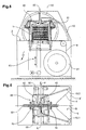
Figuren 5 und 6 zeigen eine beispielhafte Ausführungsform der erfindungsgemässen Vorrichtung als Seitenansicht in Förderrichtung (Figur 5) und als Draufsicht auf die Auflagefläche 2 (Figur 6). Die Vorrichtung ist für eine Kreuzumreifung ausgerüstet, wobei die Längsumreifung durchgeführt wird, wie dies im Zusammenhang mit der Figur 1 beschrieben wurde. Für die Querumreifung ist in an sich bekannter Weise ein stationärer Schlaufenkanal 30 vorgesehen, der sich in einer Ebene quer zur Förderrichtung F (Querumreifungsebene Q) um die Umreifungsposition biegt. Das zu umreifende Objekt ist beispielsweise ein Stapel von Zeitungen, Zeitschriften oder anderen flachen Gegenständen. Das Umreifungsmaterial 6 wird für die Längs- und für die Querumreifung von je einer Vorratsrolle 31 abgezogen. Mit einer entsprechend verwundenen und gekrümmten Zuführung (nicht dargestellt) der einen der beiden Zuführungen wird es möglich, die beiden Vorratsrollen 31 in der dargestellten Art koaxial und damit platzsparend anzuordnen. Figures 5 and 6 show an exemplary embodiment of the inventive device as a side view in the conveying direction (Figure 5) and as a plan view of the support surface 2 (Figure 6). The device is equipped for cross-strapping, wherein the longitudinal strapping is performed, as described in connection with FIG. For the Querumreifung a
Die Vorrichtung weist ferner Pressmittel 40 für die Pressung des zu umreifenden Objekts 1 vor und während der Umreifung und Antriebsmittel 41 für die Pressmittel auf. Diese Pressmittel 40 sind zusätzlich zur Pressfunktion auch für weitere Funktionen ausgerüstet und werden im Zusammenhang mit der Figur 7 detaillierter beschrieben.The apparatus further comprises pressing means 40 for pressing the
Die in den Figuren 5 und 6 dargestellte Vorrichtung ist ausgerüstet für eine auf die Längsumreifung folgende Querumreifung, wobei die beiden Umreifungsprozesse sich auch zeitlich mindestens beschränkt überlappen können. Aus diesem Grunde erstreckt sich der Schlaufenkanal 30 für die Querumreifung ausserhalb des Weges der Längsschlaufe und spannt sich unterbruchslos über die Umreifungsposition. Die Schlaufenführung (Gleitschienen 10.1 und 10.2) enden unterhalb des Schlaufenkanals 30 für die Querumreifung, der ausserhalb des nutförmigen Schlaufenkanals 4 für die Längsumreifung aus der Auflagefläche aufsteigt. Um die für die beiden Umreifungen notwendigen Schlaufenlängen zu erreichen, kann der nutförmige Schlaufenkanal 4, wie dies in der Figur 6 dargestellt ist, nicht nur konvexe sondern auch konkave Biegungen aufweisen. Wenn nur eine Längsumreifung vorgesehen ist, kann auf die konkave Biegung verzichtet werden (Kanalverlauf 4', stichpunktiert dargestellt).The apparatus shown in FIGS. 5 and 6 is equipped for transverse strapping following the longitudinal strapping, wherein the two strapping processes can also overlap at least to a limited extent in terms of time. For this reason, the
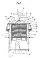
Figur 7 zeigt als Seitenansicht wie Figur 5 aber in mehr Detail die Umreifungsposition und insbesondere die Pressmittel 40 der Vorrichtung gemäss Figuren 5 und 6. Diese Pressmittel 40 bestehen, wie auch aus der Figur 6 ersichtlich, aus vier relativ zu den Umreifungsebenen (Längsumreifungsebene L, Querumreifungsebene Q) spiegelbildlich angeordneten, Presselementen 42. Für eine Umreifungsposition, die für nur eine Umreifung ausgerüstet ist, wird vorteilhafterweise ein entsprechendes Paar von Presselementen vorgesehen. FIG. 7 shows as a side view like FIG. 5 but in more detail the strapping position and in particular the pressing means 40 of the device according to FIGS. 5 and 6. As can also be seen from FIG. 6, these pressing means 40 consist of four relative to the strapping planes (longitudinal strapping plane L, FIG. Querumreifungsebene Q) arranged in mirror image,
Die Presselemente 42 sind mit Hilfe eines gemeinsamen Antriebs 41 auf das zu umreifende Objekt 1 absenkbar. Der Antrieb 41 ist beispielsweise als unterhalb der Auflagefläche 2 angeordneter Kettenzug 43 mit daran angekoppelten Traversen 44 und mit für jedes Presselement 42 je einem senkrechten, seitlich von der Umreifungsposition angeordneten Träger 45 realisiert. Die Presselemente 42 können als einfache relativ zu den senkrechten Trägern 45 stationär angeordnete Pressplatten ausgebildet sein. Vorteilhafterweise sind sie aber, wie in der Figur 7 dargestellt, als winklige Kniehebel 46 ausgestaltet, die um eine Achse 47 im Bereich der oberen Enden der senkrechten Träger 45 kippbar angeordnet sind und die je einen sich über die Umreifungsposition erstreckenden, pressenden Teil 46.1 und einen sich seitlich davon erstreckenden Teil 46.2 aufweisen. Der Kniehebelteil 46.2 wird beispielsweise mittels Feder 48 vom senkrechten Träger 45 distanziert, derart, dass der Kniehebelteil 46.1 bei unkomprimierter Feder 48 von der Drehachse 47 aus gegen unten gerichtet ist.The
Wenn das zu umreifende Objekt 1 in die Umreifungsposition gefördert wird, befinden sich die Traversen 44 und damit auch die senkrechten Träger 45 und die Kniehebel 46 in einer obersten Position, die für die Kniehebel in Figur 7 strichpunktiert dargestellt ist. Sobald das zu umreifende Objekt in der Umreifungsposition positioniert ist, werden die Presselemente 42 nach unten gefahren. Die Enden der pressenden Kniehebelteile 46.1 treffen dabei zuerst auf das zu umreifende Objekt und diese Kniehebelteile werden beim weiteren Absenken unter Kompression der Federn 48 in eine waagrechte Position gepresst. Wenn eine genügende Presskraft erreicht ist, kann die eigentliche Umreifung beginnen.When the
Die Presselemente 42 können gleichzeitig auch eine Führungsfunktion für eine von der Schlaufenführung 10 entlassene Schlaufe übernehmen. Zu diesem Zwecke sind an den beiden Enden der Kniehebelteile 46.1 und 46.2 und gegebenenfalls auch dazwischen frei drehbare Rollen 50 angeordnet, von denen ein Führungsband 51, dessen beide Enden an stationären Teilen der Vorrichtung befestigt sind, in einer vorgegebenen Position gehalten wird. Jedem der vier Presselemente 42 ist mindestens ein derartiges Führungsband 51 zugeordnet. Die Führungsbänder 51 erstrecken sich auf der einen Seite der Längsumreifungsebene L vom Schlaufenkanal 30 für die Querumreifung auf der anderen Seite der Längsumreifungsebene L vom Ende der Schlaufenführung 10 zum Ende des pressenden Kniehebelteils 46.1, von da zum Ende des seitlichen Kniehebelteils 46.2 und von da gegen die Auflagefläche. Die Führungsbänder 51 werden gegebenenfalls mit geeigneten, nicht dargestellten Mitteln leicht gespannt gehalten.The
Wie aus der Figur 7 ersichtlich ist, bilden die obersten Teile der Führungsbänder 51 einen zur Längsumreifungsebene L parallelen, über der Schlaufenführung 10 offenen Führungskanal 55, in dem geführt die Schlaufe des Längsumreifungsmaterials sich vom Ende der Schlaufenführung 10 auf das zu umreifende Objekt 1 bewegt.As can be seen from FIG. 7, the uppermost parts of the
In den Figuren 5 bis 7 ist ferner ein Mittel dargestellt, mit dessen Hilfe ein vor der Umreifung auf das zu umreifende Objekt 1 aufzubringendes Deckblatt 60 für die Aufbringung positionierbar ist. Es handelt sich dabei um vier wiederum spiegelbildlich zu den beiden Umreifungsebenen L und Q über der Umreifungsposition angeordnete, im wesentlichen stationäre Blattträger 61 (für einfache Umreifung zwei Blattträger). Die Höhe der Blattträger 61 über der Auflagefläche 2 ist derart, dass auch das höchste zu umreifende Objekt in ungepresstem Zustand darunter in die Umreifungsposition gefördert werden kann.FIGS. 5 to 7 further show a means by means of which a
Die Deckblätter 60 werden synchronisiert mit aufeinanderfolgenden Umreifungen in nicht näher dargestellter Weise beispielsweise mit der Förderrichtung F gleichgerichtet und von oben auf den Blattträgern 61 positioniert und werden dann von den vorauslaufenden Enden der pressenden Kniehebelteile 46.1 nach unten gebogen und damit von den Blattträgem 61 gezogen und auf dem zu umreifenden Objekt 1 positioniert und an diesem angepresst.The
Figuren 8 und 9 zeigen eine weitere, beispielhafte Ausführungsform der erfindungsgemässen Vorrichtung. Diese Vorrichtung unterscheidet sich von den Vorrichtungen der vorangehenden Figuren dadurch, dass die zur Auflagefläche 2 der Umreifungsposition parallele Förderrichtung F nur die Richtung der Wegförderung des umreiften Objektes 1 aus der Umreifgungsposition ist und das zu umreifende Objekt 1 von oben, das heisst, im wesentlichen senkrecht zur Auflagefläche 2 und zur Förderrichtung F (Zuführungsrichtung F') in die Umreifungsposition gebracht wird. Um dies zu ermöglichen, ist lediglich dafür zu sorgen, dass die beiden Gleitschienen 10.1 und 10.2 oder ein anders ausgestaltetes Schlaufenführungsmittel sich nicht über die Umreifungsposition erstreckt oder wölbt, sondern lediglich gegen diese, den Zugang zur Umreifungsposition von oben also frei lässt. Dies ist aus der Figur 9 deutlich ersichtlich. FIGS. 8 and 9 show a further, exemplary embodiment of the device according to the invention. This device differs from the devices of the preceding figures in that the conveying direction F parallel to the
Das in der Vorrichtung gemäss Figuren 8 und 9 umreifte Objekt 1 ist beispielsweise ein Stapel oder Kreuzstapel von flachen Gegenständen, der beispielsweise in der Umreifungsposition durch Zuführung von Stapelsektionen 1.1 von oben (Zuführungsrichtung F') in der Umreifungsposition gebildet wird. Dafür ist diese beispielsweise mit Eckführungen 70 versehen, die mindestens ausgangsseitig für das Ausstossen des umreiften Stapels verschieb- oder versenkbar sind. Wie in der Figur 8 gezeigt ist, können die Stapelsektionen direkt über der Umreifungsposition durch Stapelung von zugeführten Schuppenstromsektionen gebildet werden.The
Auch im Falle einer Zuführung von oben kann die Umreifung mit Hilfe der Schlaufenführung eine Längs- oder Querumreifung (relativ zur Wegförderrichtung F) sein. Eine zusätzliche, mindesten teilweise gleichzeitig durchgeführte Umreifung (Kreuzumreifung) ist mindestens mit einem weiteren Schlaufenkanal, wie er in den Figuren 5 und 6 für die zusätzliche Querumreifung vorgeschlagen wird, nicht möglich (keine Zugänglichkeit von oben). Eine Kreuzumreifung kann aber mit Hilfe einer in Förderrichtung F auf die Umreifungsposition gemäss Erfindung (Längsumreifung) folgende, weitere Umreifungsposition 71 (Querumreifung) erreicht werden. Die weitere Umreifungsposition ist dabei beispielsweise mit einem quer zur Förderrichtung F stehenden, in einer im wesentlichen senkrechten Ebene verlaufenden, weiteren Schlaufenkanal 30 ausgerüstet.Even in the case of a supply from above, the strapping with the aid of the loop guide can be a longitudinal or Querumreifung (relative to the Wegförderrichtung F). An additional, at least partially simultaneous strapping (cross strapping) is not possible with at least one further loop channel, as it is proposed in Figures 5 and 6 for the additional Querumreifung (no accessibility from above). However, a cross strapping can be achieved by means of a further strapping position 71 (transverse strapping) following in the conveying direction F to the strapping position according to the invention (longitudinal strapping). The further strapping position is equipped with, for example, a
Presselemente und Elemente zur Zuführung von Deckblättern, wie sie in den Figuren 6 und 7 dargestellt sind, sind für die Ausführungsform der erfindungsgemässen Vorrichtung, wie sie in den Figuren 8 und 9 dargestellt ist, ebenfalls derart auszurüsten (z.B. seitlich verschiebbar), dass sie der Zuführung des zu umreifenden Objektes von oben nicht im Wege stehen.Pressing elements and elements for feeding cover sheets, as shown in FIGS. 6 and 7, for the embodiment of the device according to the invention, as shown in FIGS. 8 and 9, likewise have to be equipped in such a way (eg laterally displaceable) that they are the same Supply of the object to be strapped from above does not stand in the way.
Claims (17)
- Strapping installation suitable for strapping objects (1), in particular stacks of printed products such as newspapers or periodicals, using a strap (6), the installation comprising a strapping position with a bearing surface (2), means for positioning the objects to be strapped in the strapping position, and means for removing the strapped objects from the strapping position in a conveying direction (F) oriented essentially parallel to the bearing surface (2), the installation further comprising a fastening region (3) located in the strapping position and equipped for supplying the strap (6) into a loop channel (4), for securing a loop end (7), for retracting the strap (6) from the loop channel (4), and for fastening and severing a completed strapping, wherein the loop channel (4) extends from either side of the fastening region (3) in the shape of a groove in the bearing surface (2), characterized in that the installation further comprises a loop guide (10) being stationary during the strapping procedure, which loop guide rises from the bearing surface (2) inside of the loop channel (4) and on one side of the strapping position and arches across or towards the strapping position in such a manner that it does not obstruct positioning of the objects to be strapped (1) in the strapping position and such that a strap loop (6.2) slides on an outer surface of the loop guide (10), and the strap loop (6.2) being supported and guided by beginning and end of the loop channel (4) and by the loop guide (10) is the shorter the higher it rises on the loop guide (10).
- Strapping installation according to claim 1, characterized in that the means for positioning the object (1) to be strapped in the strapping position is equipped for supply from above towards the strapping position or essentially in the conveying direction (F), and that the loop guide (10) arches towards the strapping position.
- Strapping installation according to claim 1, characterized in that the means for positioning the object (1) to be strapped in the strapping position is equipped for supply essentially in the conveying direction (F) and that the loop guide (10) arches across the strapping position.
- Strapping installation according to one of claims 1 to 3, characterized in that, for longitudinal strapping, a beginning and an end of the groove-shaped loop channel (4) is aligned parallel to the conveying direction (F), and that the installation is further equipped for transverse strapping in the strapping position or in an additional strapping position following the strapping position in the conveying direction (F).
- Strapping installation according to claim 4, characterized in that it comprises a further loop channel (30) extending at a right angle to the conveying direction (F).
- Strapping installation according to one of claims 1 to 5, characterized in that the loop guide (10) comprises two or more slide rails (10.1, 10.2).
- Strapping installation according to claim 6, characterized in that the groove-shaped loop channel (4) comprises a concave bend between the guide rails (10.1 and 10.2) and that, in the area of the concave bend of the groove-shaped loop channel (4), an element rising from the bearing surface (2) is arranged on the outside of the loop channel (4).
- Strapping installation according to claims 5 and 7, characterized in that the element rising from the bearing surface (2) outside of the groove-shaped loop channel is the further loop channel (30), which extends across the strapping position above the loop guide (10).
- Strapping installation according to one of claims 1 to 8, characterized in that, at least in the area where the loop guide (10) rises from the bearing surface, the groove-shaped loop channel (4) comprises an inner wall (4.2) slanting towards the bearing surface (2).
- Strapping installation according to one of claims 1 to 9, characterized in that at least part of the groove-shaped loop channel (4) is closeable.
- Strapping installation according to one of claims 1 to 10 characterized in that the fastening region (3) is equipped to hold a tape-shaped strap (6) with its width parallel to the bearing surface (2) and that the loop channel (4) comprises twists such that, in bent channel areas, the tape-shaped strap (6) is positioned with its width vertical to the bearing surface (2).
- Strapping installation according to one of claims 1 to 10, characterized in that the fastening region (3) comprises a rotating strap holding means (13, 14), by which the tape-shaped strap (6) is rotateable from a position, in which its width is vertical to the bearing surface (2), to a position, in which its width is parallel with the bearing surface (2).
- Strapping installation according to one of claims 1 to 10, characterized in that the fastening region (3) is equipped for unchangeably holding a tape-shaped strap (6) with its width vertical to the bearing surface (2) and for fastening the strap in this position.
- Strapping installation according to one of claims 1 to 13, characterized in that it further comprises two or four pressing elements which are capable to be lowered (42).
- Strapping installation according to claim 14, characterized in that the pressing elements (42) are designed as knee levers (46) being rotateable around an axis (47).
- Strapping installation according to one of claims 14 or 15, characterized in that the pressing elements (42) comprise guide tapes (51) for guiding the strap loop (6), which guide tapes form a guide channel (55) above the strapping position, which guide channel (55) extends from the end of the loop guide (10) towards the strapping position and is open above the end of the loop guide (10).
- Strapping installation according to one of claims 14 to 16, characterized in that it further comprises means for positioning a cover sheet (60) on the object (1) to be strapped and that the pressing elements (42) are equipped for displacing the cover sheet (60) while being lowered on to the object (1) to be strapped.
Applications Claiming Priority (3)
| Application Number | Priority Date | Filing Date | Title |
|---|---|---|---|
| CH112702 | 2002-06-28 | ||
| CH11272002 | 2002-06-28 | ||
| PCT/CH2003/000325 WO2004002829A1 (en) | 2002-06-28 | 2003-05-22 | Strapping device |
Publications (2)
| Publication Number | Publication Date |
|---|---|
| EP1517836A1 EP1517836A1 (en) | 2005-03-30 |
| EP1517836B1 true EP1517836B1 (en) | 2006-08-16 |
Family
ID=29783981
Family Applications (1)
| Application Number | Title | Priority Date | Filing Date |
|---|---|---|---|
| EP03720077A Expired - Lifetime EP1517836B1 (en) | 2002-06-28 | 2003-05-22 | Strapping device |
Country Status (9)
| Country | Link |
|---|---|
| US (1) | US7086213B2 (en) |
| EP (1) | EP1517836B1 (en) |
| AT (1) | ATE336430T1 (en) |
| AU (1) | AU2003223825B2 (en) |
| CA (1) | CA2490910A1 (en) |
| DE (1) | DE50304670D1 (en) |
| DK (1) | DK1517836T3 (en) |
| ES (1) | ES2270007T3 (en) |
| WO (1) | WO2004002829A1 (en) |
Families Citing this family (9)
| Publication number | Priority date | Publication date | Assignee | Title |
|---|---|---|---|---|
| DE102004051029B3 (en) * | 2004-10-08 | 2005-12-08 | Schneider & Ozga Ohg | Device for tying up objects has support table and a slide guide for the tie belt with a U-shaped front edge element with straight front section and two separate side arms |
| DE102006038318A1 (en) * | 2006-08-15 | 2008-02-21 | Maschinenfabrik Gerd Mosca Ag | calender production |
| DE102006038319B4 (en) * | 2006-08-15 | 2018-02-22 | Mosca Gmbh | Longitudinal strapping device and method for strapping |
| ES2397264T3 (en) * | 2010-09-08 | 2013-03-05 | Titan Umreifungstechnik Gmbh & Co.Kg | Procedure for placing strips around packing pieces |
| US8443723B2 (en) * | 2010-10-27 | 2013-05-21 | Tekpak Corporation | Cross-strapping device |
| CH705745A2 (en) * | 2011-11-14 | 2013-05-15 | Illinois Tool Works | Strapper. |
| CH705743A2 (en) | 2011-11-14 | 2013-05-15 | Illinois Tool Works | Strapper. |
| US10820526B2 (en) * | 2018-07-10 | 2020-11-03 | Deere & Company | Agricultural baler including crop package banding system and method |
| CN116119082B (en) * | 2023-04-17 | 2023-06-13 | 烟台安信机电科技有限公司 | A feed bin for tying up part fast |
Family Cites Families (12)
| Publication number | Priority date | Publication date | Assignee | Title |
|---|---|---|---|---|
| US4079667A (en) * | 1976-12-20 | 1978-03-21 | Signode Corporation | Method of forming and tensioning a strap loop about a package |
| US4077313A (en) * | 1976-12-20 | 1978-03-07 | Signode Corporation | Method of tensioning and joining a formed strap loop about a package |
| USRE31353E (en) * | 1976-12-20 | 1983-08-23 | Signode Corporation | Expanding strap loop forming and friction fusion machine |
| US4062278A (en) * | 1976-12-20 | 1977-12-13 | Signode Corporation | Expanding strap loop forming and friction fusion machine |
| US4378262A (en) * | 1981-02-04 | 1983-03-29 | Signode Corporation | Method and apparatus for forming and tensioning a strap loop about a package |
| US5078057A (en) * | 1990-01-05 | 1992-01-07 | Illinois Tool Works Inc. | Binding machine, such as strapping machine |
| EP0545105B1 (en) * | 1991-11-30 | 1995-05-31 | Georg Lang | Device for tying a package with a strap |
| DE4230730B4 (en) * | 1992-09-14 | 2005-05-25 | Georg Lang | Strapping machine with a tape guide frame |
| DE19615009B4 (en) * | 1996-04-16 | 2005-09-29 | Smb Schwede Maschinenbau Gmbh | Stacker with strapping device |
| DK0905025T3 (en) * | 1997-09-27 | 2000-10-16 | Ssb Strapping Systeme Bindlach | strapping |
| EP1207107B1 (en) * | 2000-11-20 | 2004-08-18 | Ferag AG | Strapping apparatus |
| DE10357829A1 (en) * | 2003-12-09 | 2005-07-28 | Signode Bernpak Gmbh | Apparatus for longitudinally gripping a package, in particular a stack of newspapers, magazines or the like. |
-
2003
- 2003-05-22 AT AT03720077T patent/ATE336430T1/en not_active IP Right Cessation
- 2003-05-22 DE DE50304670T patent/DE50304670D1/en not_active Expired - Lifetime
- 2003-05-22 DK DK03720077T patent/DK1517836T3/en active
- 2003-05-22 WO PCT/CH2003/000325 patent/WO2004002829A1/en active IP Right Grant
- 2003-05-22 US US10/519,296 patent/US7086213B2/en not_active Expired - Fee Related
- 2003-05-22 CA CA002490910A patent/CA2490910A1/en not_active Abandoned
- 2003-05-22 AU AU2003223825A patent/AU2003223825B2/en not_active Ceased
- 2003-05-22 EP EP03720077A patent/EP1517836B1/en not_active Expired - Lifetime
- 2003-05-22 ES ES03720077T patent/ES2270007T3/en not_active Expired - Lifetime
Also Published As
| Publication number | Publication date |
|---|---|
| WO2004002829A1 (en) | 2004-01-08 |
| DK1517836T3 (en) | 2007-02-12 |
| US7086213B2 (en) | 2006-08-08 |
| AU2003223825A1 (en) | 2004-01-19 |
| AU2003223825B2 (en) | 2008-11-06 |
| EP1517836A1 (en) | 2005-03-30 |
| ES2270007T3 (en) | 2007-04-01 |
| DE50304670D1 (en) | 2006-09-28 |
| CA2490910A1 (en) | 2004-01-08 |
| US20050229551A1 (en) | 2005-10-20 |
| ATE336430T1 (en) | 2006-09-15 |
Similar Documents
| Publication | Publication Date | Title |
|---|---|---|
| DE2710474C2 (en) | ||
| DE3512737C2 (en) | Feeder of booklets, sheets and similar products for feeding devices in packaging machines, bookbinding machines and the like. | |
| DE69505767T2 (en) | Method and device for a strapping machine | |
| EP0144861A2 (en) | Machine for the zig-zag folding and stacking of webs | |
| EP0968919B1 (en) | Method and device for enveloping quadrangular objects with a tape-like enveloping material | |
| DE2615560A1 (en) | MACHINE FOR LINGING DIFFERENT COMPONENTS | |
| EP1184283A1 (en) | Method and device for tying stacks of printing products | |
| EP0890509A1 (en) | Method and device for tying single objects or stacks of objects | |
| EP1517836B1 (en) | Strapping device | |
| EP1541470B1 (en) | Device for applying a longitudinal strap around an object such as in particular a bundle of newspapers or magazines | |
| DE3708267A1 (en) | RIBBON GUIDE FOR A RETURNING MACHINE | |
| CH656861A5 (en) | DEVICE FOR STORING PAPER SHEET. | |
| DE19533086A1 (en) | Method and device for stacking flat products, in particular printed products | |
| DE3619939C2 (en) | Method and device for the intermediate storage of printed products resulting in scale formation | |
| DE4016484C2 (en) | Packing device for web rolls | |
| EP0680881B1 (en) | Device for binding articles | |
| DE68912280T2 (en) | Adhesive tape application unit for cardboard adhesive tape application machines with an improved return movement of the input pressure roller. | |
| EP0937647B1 (en) | Device for binding goods with a strap | |
| DE2403155A1 (en) | BINDING MACHINE FOR STAPLING PERFORATED SHEETS | |
| DE29917881U1 (en) | Strapping machine for strapping a stack of goods | |
| EP1515894B1 (en) | System for packaging a flexible web that is layered in zigzag loops, in particular a textile web | |
| EP2678171B1 (en) | Filling station and method for filling an envelope | |
| WO2007107267A1 (en) | Method and apparatus for transporting label strips | |
| DE3902297A1 (en) | METHOD AND DEVICE FOR CONVERTING BUNDLED SIGNATURES INTO A FAN-FLOW | |
| DE2609672A1 (en) | METHOD AND DEVICE FOR WRAPPING AN OBJECT WITH A BOW OR TAPE |
Legal Events
| Date | Code | Title | Description |
|---|---|---|---|
| PUAI | Public reference made under article 153(3) epc to a published international application that has entered the european phase |
Free format text: ORIGINAL CODE: 0009012 |
|
| 17P | Request for examination filed |
Effective date: 20041210 |
|
| AK | Designated contracting states |
Kind code of ref document: A1 Designated state(s): AT BE BG CH CY CZ DE DK EE ES FI FR GB GR HU IE IT LI LU MC NL PT RO SE SI SK TR |
|
| AX | Request for extension of the european patent |
Extension state: AL LT LV MK |
|
| DAX | Request for extension of the european patent (deleted) | ||
| GRAP | Despatch of communication of intention to grant a patent |
Free format text: ORIGINAL CODE: EPIDOSNIGR1 |
|
| GRAS | Grant fee paid |
Free format text: ORIGINAL CODE: EPIDOSNIGR3 |
|
| GRAA | (expected) grant |
Free format text: ORIGINAL CODE: 0009210 |
|
| AK | Designated contracting states |
Kind code of ref document: B1 Designated state(s): AT BE BG CH CY CZ DE DK EE ES FI FR GB GR HU IE IT LI LU MC NL PT RO SE SI SK TR |
|
| PG25 | Lapsed in a contracting state [announced via postgrant information from national office to epo] |
Ref country code: IT Free format text: LAPSE BECAUSE OF FAILURE TO SUBMIT A TRANSLATION OF THE DESCRIPTION OR TO PAY THE FEE WITHIN THE PRESCRIBED TIME-LIMIT;WARNING: LAPSES OF ITALIAN PATENTS WITH EFFECTIVE DATE BEFORE 2007 MAY HAVE OCCURRED AT ANY TIME BEFORE 2007. THE CORRECT EFFECTIVE DATE MAY BE DIFFERENT FROM THE ONE RECORDED. Effective date: 20060816 Ref country code: CZ Free format text: LAPSE BECAUSE OF FAILURE TO SUBMIT A TRANSLATION OF THE DESCRIPTION OR TO PAY THE FEE WITHIN THE PRESCRIBED TIME-LIMIT Effective date: 20060816 Ref country code: RO Free format text: LAPSE BECAUSE OF FAILURE TO SUBMIT A TRANSLATION OF THE DESCRIPTION OR TO PAY THE FEE WITHIN THE PRESCRIBED TIME-LIMIT Effective date: 20060816 Ref country code: SK Free format text: LAPSE BECAUSE OF FAILURE TO SUBMIT A TRANSLATION OF THE DESCRIPTION OR TO PAY THE FEE WITHIN THE PRESCRIBED TIME-LIMIT Effective date: 20060816 Ref country code: IE Free format text: LAPSE BECAUSE OF FAILURE TO SUBMIT A TRANSLATION OF THE DESCRIPTION OR TO PAY THE FEE WITHIN THE PRESCRIBED TIME-LIMIT Effective date: 20060816 Ref country code: FI Free format text: LAPSE BECAUSE OF FAILURE TO SUBMIT A TRANSLATION OF THE DESCRIPTION OR TO PAY THE FEE WITHIN THE PRESCRIBED TIME-LIMIT Effective date: 20060816 Ref country code: GB Free format text: LAPSE BECAUSE OF FAILURE TO SUBMIT A TRANSLATION OF THE DESCRIPTION OR TO PAY THE FEE WITHIN THE PRESCRIBED TIME-LIMIT Effective date: 20060816 Ref country code: SI Free format text: LAPSE BECAUSE OF FAILURE TO SUBMIT A TRANSLATION OF THE DESCRIPTION OR TO PAY THE FEE WITHIN THE PRESCRIBED TIME-LIMIT Effective date: 20060816 |
|
| REG | Reference to a national code |
Ref country code: GB Ref legal event code: FG4D Free format text: NOT ENGLISH |
|
| REG | Reference to a national code |
Ref country code: CH Ref legal event code: EP |
|
| REG | Reference to a national code |
Ref country code: IE Ref legal event code: FG4D Free format text: LANGUAGE OF EP DOCUMENT: GERMAN |
|
| REF | Corresponds to: |
Ref document number: 50304670 Country of ref document: DE Date of ref document: 20060928 Kind code of ref document: P |
|
| REG | Reference to a national code |
Ref country code: CH Ref legal event code: NV Representative=s name: FREI PATENTANWALTSBUERO AG |
|
| PG25 | Lapsed in a contracting state [announced via postgrant information from national office to epo] |
Ref country code: BG Free format text: LAPSE BECAUSE OF FAILURE TO SUBMIT A TRANSLATION OF THE DESCRIPTION OR TO PAY THE FEE WITHIN THE PRESCRIBED TIME-LIMIT Effective date: 20061116 |
|
| REG | Reference to a national code |
Ref country code: SE Ref legal event code: TRGR |
|
| PG25 | Lapsed in a contracting state [announced via postgrant information from national office to epo] |
Ref country code: PT Free format text: LAPSE BECAUSE OF FAILURE TO SUBMIT A TRANSLATION OF THE DESCRIPTION OR TO PAY THE FEE WITHIN THE PRESCRIBED TIME-LIMIT Effective date: 20070116 |
|
| REG | Reference to a national code |
Ref country code: DK Ref legal event code: T3 |
|
| GBT | Gb: translation of ep patent filed (gb section 77(6)(a)/1977) |
Effective date: 20070131 |
|
| REG | Reference to a national code |
Ref country code: IE Ref legal event code: FD4D |
|
| REG | Reference to a national code |
Ref country code: ES Ref legal event code: FG2A Ref document number: 2270007 Country of ref document: ES Kind code of ref document: T3 |
|
| EN | Fr: translation not filed | ||
| PLBE | No opposition filed within time limit |
Free format text: ORIGINAL CODE: 0009261 |
|
| STAA | Information on the status of an ep patent application or granted ep patent |
Free format text: STATUS: NO OPPOSITION FILED WITHIN TIME LIMIT |
|
| 26N | No opposition filed |
Effective date: 20070518 |
|
| BERE | Be: lapsed |
Owner name: FERAG AG Effective date: 20070531 |
|
| PG25 | Lapsed in a contracting state [announced via postgrant information from national office to epo] |
Ref country code: MC Free format text: LAPSE BECAUSE OF NON-PAYMENT OF DUE FEES Effective date: 20070531 |
|
| PG25 | Lapsed in a contracting state [announced via postgrant information from national office to epo] |
Ref country code: BE Free format text: LAPSE BECAUSE OF NON-PAYMENT OF DUE FEES Effective date: 20070531 |
|
| PG25 | Lapsed in a contracting state [announced via postgrant information from national office to epo] |
Ref country code: FR Free format text: LAPSE BECAUSE OF FAILURE TO SUBMIT A TRANSLATION OF THE DESCRIPTION OR TO PAY THE FEE WITHIN THE PRESCRIBED TIME-LIMIT Effective date: 20070511 Ref country code: GR Free format text: LAPSE BECAUSE OF FAILURE TO SUBMIT A TRANSLATION OF THE DESCRIPTION OR TO PAY THE FEE WITHIN THE PRESCRIBED TIME-LIMIT Effective date: 20061117 |
|
| PG25 | Lapsed in a contracting state [announced via postgrant information from national office to epo] |
Ref country code: EE Free format text: LAPSE BECAUSE OF FAILURE TO SUBMIT A TRANSLATION OF THE DESCRIPTION OR TO PAY THE FEE WITHIN THE PRESCRIBED TIME-LIMIT Effective date: 20060816 |
|
| PG25 | Lapsed in a contracting state [announced via postgrant information from national office to epo] |
Ref country code: AT Free format text: LAPSE BECAUSE OF NON-PAYMENT OF DUE FEES Effective date: 20070522 |
|
| PG25 | Lapsed in a contracting state [announced via postgrant information from national office to epo] |
Ref country code: FR Free format text: LAPSE BECAUSE OF FAILURE TO SUBMIT A TRANSLATION OF THE DESCRIPTION OR TO PAY THE FEE WITHIN THE PRESCRIBED TIME-LIMIT Effective date: 20060816 |
|
| PGFP | Annual fee paid to national office [announced via postgrant information from national office to epo] |
Ref country code: ES Payment date: 20090521 Year of fee payment: 7 Ref country code: NL Payment date: 20090527 Year of fee payment: 7 |
|
| PG25 | Lapsed in a contracting state [announced via postgrant information from national office to epo] |
Ref country code: LU Free format text: LAPSE BECAUSE OF NON-PAYMENT OF DUE FEES Effective date: 20070522 Ref country code: CY Free format text: LAPSE BECAUSE OF FAILURE TO SUBMIT A TRANSLATION OF THE DESCRIPTION OR TO PAY THE FEE WITHIN THE PRESCRIBED TIME-LIMIT Effective date: 20060816 |
|
| PGFP | Annual fee paid to national office [announced via postgrant information from national office to epo] |
Ref country code: IT Payment date: 20090523 Year of fee payment: 7 |
|
| PG25 | Lapsed in a contracting state [announced via postgrant information from national office to epo] |
Ref country code: HU Free format text: LAPSE BECAUSE OF FAILURE TO SUBMIT A TRANSLATION OF THE DESCRIPTION OR TO PAY THE FEE WITHIN THE PRESCRIBED TIME-LIMIT Effective date: 20070217 Ref country code: TR Free format text: LAPSE BECAUSE OF FAILURE TO SUBMIT A TRANSLATION OF THE DESCRIPTION OR TO PAY THE FEE WITHIN THE PRESCRIBED TIME-LIMIT Effective date: 20060816 |
|
| PGFP | Annual fee paid to national office [announced via postgrant information from national office to epo] |
Ref country code: GB Payment date: 20090522 Year of fee payment: 7 |
|
| REG | Reference to a national code |
Ref country code: NL Ref legal event code: V1 Effective date: 20101201 |
|
| GBPC | Gb: european patent ceased through non-payment of renewal fee |
Effective date: 20100522 |
|
| PG25 | Lapsed in a contracting state [announced via postgrant information from national office to epo] |
Ref country code: NL Free format text: LAPSE BECAUSE OF NON-PAYMENT OF DUE FEES Effective date: 20101201 Ref country code: IT Free format text: LAPSE BECAUSE OF NON-PAYMENT OF DUE FEES Effective date: 20100522 |
|
| REG | Reference to a national code |
Ref country code: ES Ref legal event code: FD2A Effective date: 20110711 |
|
| PG25 | Lapsed in a contracting state [announced via postgrant information from national office to epo] |
Ref country code: ES Free format text: LAPSE BECAUSE OF NON-PAYMENT OF DUE FEES Effective date: 20110629 |
|
| PGFP | Annual fee paid to national office [announced via postgrant information from national office to epo] |
Ref country code: CH Payment date: 20110518 Year of fee payment: 9 |
|
| PG25 | Lapsed in a contracting state [announced via postgrant information from national office to epo] |
Ref country code: ES Free format text: LAPSE BECAUSE OF NON-PAYMENT OF DUE FEES Effective date: 20100523 |
|
| PGFP | Annual fee paid to national office [announced via postgrant information from national office to epo] |
Ref country code: DK Payment date: 20120521 Year of fee payment: 10 Ref country code: DE Payment date: 20120523 Year of fee payment: 10 |
|
| PGFP | Annual fee paid to national office [announced via postgrant information from national office to epo] |
Ref country code: SE Payment date: 20120522 Year of fee payment: 10 |
|
| PG25 | Lapsed in a contracting state [announced via postgrant information from national office to epo] |
Ref country code: GB Free format text: LAPSE BECAUSE OF FAILURE TO SUBMIT A TRANSLATION OF THE DESCRIPTION OR TO PAY THE FEE WITHIN THE PRESCRIBED TIME-LIMIT Effective date: 20100522 |
|
| REG | Reference to a national code |
Ref country code: CH Ref legal event code: PL |
|
| REG | Reference to a national code |
Ref country code: SE Ref legal event code: EUG |
|
| PG25 | Lapsed in a contracting state [announced via postgrant information from national office to epo] |
Ref country code: LI Free format text: LAPSE BECAUSE OF NON-PAYMENT OF DUE FEES Effective date: 20130531 Ref country code: SE Free format text: LAPSE BECAUSE OF NON-PAYMENT OF DUE FEES Effective date: 20130523 Ref country code: CH Free format text: LAPSE BECAUSE OF NON-PAYMENT OF DUE FEES Effective date: 20130531 Ref country code: DE Free format text: LAPSE BECAUSE OF NON-PAYMENT OF DUE FEES Effective date: 20131203 |
|
| REG | Reference to a national code |
Ref country code: DK Ref legal event code: EBP Effective date: 20130531 |
|
| REG | Reference to a national code |
Ref country code: DE Ref legal event code: R119 Ref document number: 50304670 Country of ref document: DE Effective date: 20131203 |
|
| PG25 | Lapsed in a contracting state [announced via postgrant information from national office to epo] |
Ref country code: DK Free format text: LAPSE BECAUSE OF NON-PAYMENT OF DUE FEES Effective date: 20130531 |