EP1517832B1 - Zugschiffspropeller - Google Patents
Zugschiffspropeller Download PDFInfo
- Publication number
- EP1517832B1 EP1517832B1 EP03728188A EP03728188A EP1517832B1 EP 1517832 B1 EP1517832 B1 EP 1517832B1 EP 03728188 A EP03728188 A EP 03728188A EP 03728188 A EP03728188 A EP 03728188A EP 1517832 B1 EP1517832 B1 EP 1517832B1
- Authority
- EP
- European Patent Office
- Prior art keywords
- propeller
- hub
- propeller hub
- peripheral portion
- pulling
- Prior art date
- Legal status (The legal status is an assumption and is not a legal conclusion. Google has not performed a legal analysis and makes no representation as to the accuracy of the status listed.)
- Expired - Lifetime
Links
- 230000002093 peripheral effect Effects 0.000 claims description 15
- 238000007789 sealing Methods 0.000 description 11
- XLYOFNOQVPJJNP-UHFFFAOYSA-N water Substances O XLYOFNOQVPJJNP-UHFFFAOYSA-N 0.000 description 4
- 239000000463 material Substances 0.000 description 3
- 230000007704 transition Effects 0.000 description 3
- 230000005540 biological transmission Effects 0.000 description 2
- 239000002184 metal Substances 0.000 description 2
- 239000013535 sea water Substances 0.000 description 2
- 230000003247 decreasing effect Effects 0.000 description 1
- 239000000314 lubricant Substances 0.000 description 1
- 230000002035 prolonged effect Effects 0.000 description 1
- 230000001603 reducing effect Effects 0.000 description 1
- 238000011144 upstream manufacturing Methods 0.000 description 1
Images

Classifications
-
- B—PERFORMING OPERATIONS; TRANSPORTING
- B63—SHIPS OR OTHER WATERBORNE VESSELS; RELATED EQUIPMENT
- B63H—MARINE PROPULSION OR STEERING
- B63H1/00—Propulsive elements directly acting on water
- B63H1/02—Propulsive elements directly acting on water of rotary type
- B63H1/12—Propulsive elements directly acting on water of rotary type with rotation axis substantially in propulsive direction
- B63H1/14—Propellers
- B63H1/20—Hubs; Blade connections
-
- B—PERFORMING OPERATIONS; TRANSPORTING
- B63—SHIPS OR OTHER WATERBORNE VESSELS; RELATED EQUIPMENT
- B63H—MARINE PROPULSION OR STEERING
- B63H23/00—Transmitting power from propulsion power plant to propulsive elements
- B63H23/32—Other parts
- B63H23/321—Bearings or seals specially adapted for propeller shafts
-
- B—PERFORMING OPERATIONS; TRANSPORTING
- B63—SHIPS OR OTHER WATERBORNE VESSELS; RELATED EQUIPMENT
- B63H—MARINE PROPULSION OR STEERING
- B63H23/00—Transmitting power from propulsion power plant to propulsive elements
- B63H23/32—Other parts
- B63H23/34—Propeller shafts; Paddle-wheel shafts; Attachment of propellers on shafts
-
- B—PERFORMING OPERATIONS; TRANSPORTING
- B63—SHIPS OR OTHER WATERBORNE VESSELS; RELATED EQUIPMENT
- B63H—MARINE PROPULSION OR STEERING
- B63H5/00—Arrangements on vessels of propulsion elements directly acting on water
- B63H5/07—Arrangements on vessels of propulsion elements directly acting on water of propellers
- B63H5/08—Arrangements on vessels of propulsion elements directly acting on water of propellers of more than one propeller
- B63H5/10—Arrangements on vessels of propulsion elements directly acting on water of propellers of more than one propeller of coaxial type, e.g. of counter-rotative type
- B63H2005/106—Arrangements on vessels of propulsion elements directly acting on water of propellers of more than one propeller of coaxial type, e.g. of counter-rotative type with drive shafts of second or further propellers co-axially passing through hub of first propeller, e.g. counter-rotating tandem propellers with co-axial drive shafts
-
- B—PERFORMING OPERATIONS; TRANSPORTING
- B63—SHIPS OR OTHER WATERBORNE VESSELS; RELATED EQUIPMENT
- B63H—MARINE PROPULSION OR STEERING
- B63H23/00—Transmitting power from propulsion power plant to propulsive elements
- B63H23/32—Other parts
- B63H23/321—Bearings or seals specially adapted for propeller shafts
- B63H2023/323—Bearings for coaxial propeller shafts, e.g. for driving propellers of the counter-rotative type
Definitions
- the present invention relates to a pulling marine propeller comprising multiple propeller blades attached to a propeller hub, said propeller hub being attachable to a propeller shaft extending from a drive housing located downstream of the propeller, according to the characteristics of the preamble of independent claim 1.
- an outer radial sealing ring is normally applied on the propeller shaft for preventing sea water from entering the drive housing, whilst an inner radial sealing ring is applied on for preventing transmission lubricants from leaking out into the water.
- the radial sealing rings traditionally comprise lips which respond to external water pressure by pressing harder against the propeller shaft.
- excessive external pressure on the sealing ring results in largely increased frictional wear of the sealing ring, which in turn may lead to undesired leakage of sea water into the drive housing.
- the submerged drive housing In drives with pulling propellers, the submerged drive housing is often broader than the propeller hub. Consequently, a front end shoulder portion on the drive housing is formed at the transition between the hub and the housing. As water flows downstream along the periphery of the propeller hub, a significant dynamic pressure build-up is created locally as water is forced to deflect radially outwards past the shoulder portion of the drive housing, especially at high speed.
- Examples for such pulling propellers are WO 00/58151 or EP 0269272 .
- a pulling marine propeller comprising multiple propeller blades attached to a propeller hub, said propeller hub being attachable to a propeller shaft extending from a drive housing located downstream of the propeller.
- the invention is especially characterized in that the propeller hub is provided with an annular, radially outwardly flared peripheral portion at its aft end, said flared portion being arranged to axially overlap a front end shoulder portion of the drive housing.
- the axial cross-sectional profile of the outwardly flared peripheral portion of the propeller hub substantially corresponds to the axial cross-sectional profile of the front end shoulder portion of the drive housing.
- the outwardly flared peripheral portion of the propeller hub constitutes a separate aft part of the propeller hub, mounted to the remaining part of the propeller hub.
- the outwardly flared peripheral portion of the propeller hub is mounted to the remaining part of the propeller hub by means of a snap lock, said snap lock comprising a radially outwardly projecting annular locking flange on a radially recessed front connection part of the outwardly flared peripheral portion.
- the locking flange is adapted for axially locking engagement with a corresponding annular groove formed in an axially overlapping aft connection portion of the remaining part of the propeller hub.
- the outwardly flared peripheral portion is either made of plastic or another suitable material such as metal.
- the outwardly flared peripheral portion is formed as an integral aft part of the propeller hub.
- the propeller is of the twin hub, counter-rotating type.
- the shoulder portion of the drive housing exhibits a nominal cross-sectional dimension exceeding the nominal cross-sectional dimension of the propeller hub.
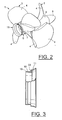
- reference numeral 1 generally denotes a twin hub, counter-rotating pulling marine propeller according to a first exemplary embodiment of the invention.
- the propeller 1 comprises a front propeller 2 and an aft propeller 3.
- both the front propeller 2 and the aft propeller 3 will hereinafter be collectively referred to as the propeller 1 .
- the propeller 1 is provided with multiple propeller blades 4 attached to a propeller hub 5.
- the propeller hub comprises a front hub 6 and an aft hub 7.
- the term propeller hub 5 will be used below as a collective term for both the front hub 6 and the aft hub 7.
- a spinner cone 8 is mounted immediately upstream of the propeller hub 1, i.e. to the left in fig. 1 .
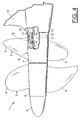
- the propeller 1 is attached to a propeller shaft 9 via the propeller hub 5, which propeller shaft 9 extends from a partially shown underwater drive housing 10 located downstream of the propeller 1.
- the propeller shaft 9 is connected to an engine (not shown) via a transmission (not shown).
- a novel feature of the invention is that the propeller hub 5 is provided with an annular, radially outwardly flared peripheral portion 11 at its aft end 12.
- the flared portion 11 is arranged in such a way as to axially overlap a front end shoulder portion 13 of the drive housing 10.
- the shoulder portion 13 of the drive housing 10 exhibits a nominal cross-sectional dimension exceeding the nominal cross-sectional dimension of the propeller hub 5.
- the term nominal cross-sectional dimension is here used as a way of describing a general dimensional increase in the transition between the propeller hub 5 and the drive housing 10. In the embodiment shown in fig. 1 , both the propeller hub 5 and the drive housing 10 has a generally circular cross-section in this transitional region.
- the term nominal cross-sectional dimension means the average diameter of each part.
- the dynamic pressure exerted on an outer radial sealing ring 14 applied between a cylindrical collar portion 15 of the drive housing 10 and the propeller shaft 9, can be drastically reduced in comparison with known designs without such an overlapping flared portion 11.
- the collar portion 15 protrudes into the propeller hub 5, and also serves as a seat for a radial slide bearing 16 for the propeller shaft 9, said slide bearing being located inside of the sealing ring 14.
- the dynamic pressure was decreased by two thirds in a pulling propeller with a flared portion according to the invention, when compared to a n otherwise corresponding conventional pulling propeller. This pressure reducing effect results in a much reduced radial pressure between the sealing ring 14 and the propeller shaft 9, which in turn means less wear and thus a prolonged expected life span of the sealing ring 14.
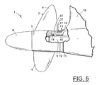
- the axial cross-sectional profile of the flared portion 11 of the propeller hub 5 substantially corresponds to the axial cross-sectional profile of the front end shoulder portion 13 of the drive housing 10.
- the flared portion 11 constitutes a separate aft part of the propeller hub 5, mounted to the remaining part of the propeller hub 5.
- the thus separately formed flared portion 11 may be made of a durable plastic material for protecting the propeller hub 5 from unintentional damage during service etc.
- the separately formed flared portion 11 may be made of other suitable materials, such as metal.
- the separately formed, annular flared portion 11 is shown detached from the propeller 1 in the enlarged side view in fig. 3 .
- the separately formed flared portion 11 of the propeller hub 5 is mounted to the remaining part of the propeller hub 5 by means of a snap lock 17.
- the snap lock 17 comprises a radially outwardly projecting annular locking flange 18 on a radially recessed front connection part 19 of the flared portion 11.
- the locking flange 18 is adapted for axially locking engagement with a corresponding annular groove 20 formed in an axially overlapping aft connection portion 21 of the remaining part of the propeller hub 5.
- the separately formed flared portion 11 also exhibits an annular axial sealing surface 22 adapted to abut a corresponding surface (not shown) on the remaining part of the propeller hub 5.
- the separately formed flared portion 11 may instead be screwed into the remaining part of the propeller hub 5.
- the flared portion 11 is formed as an integral aft part of the propeller hub 5.
- the flared portion 11 of the invention may naturally also be applied on a single pulling propeller 1. It is to be understood that the invention is by no means limited to the embodiments described above, and may be varied freely within the scope of the appended claims.
Landscapes
- Chemical & Material Sciences (AREA)
- Engineering & Computer Science (AREA)
- Combustion & Propulsion (AREA)
- Mechanical Engineering (AREA)
- Ocean & Marine Engineering (AREA)
- Structures Of Non-Positive Displacement Pumps (AREA)
- Prevention Of Electric Corrosion (AREA)
- Sealing Devices (AREA)
- Catching Or Destruction (AREA)
Claims (8)
- Zugschiffsschraube (1) mit mehreren Schraubenschaufeln (4), die an einer Schraubennabe (5) angebracht sind, wobei die Schraubennabe (5) an einer Schraubenwelle (9) angebracht werden kann, die sich von einem Antriebsgehäuse (10) aus erstreckt, das stromabwärts der Schraube (1)
dadurch gekennzeichnet, dass die Schraubennabe (5) an ihrem hinteren Ende (12) mit einem ringförmigen, sich radial nach außen erweiternden Umfangsabschnitt (11) versehen ist, wobei der sich erweiternde Abschnitt (11) so angeordnet ist, dass er einen vorderen Stirnschulterabschnitt (13) des Antriebsgehäuses (10) axial überlappt. - Zugschiffsschraube (1) nach Anspruch 1, dadurch gekennzeichnet, dass das axiale Querschnittsprofil des sich nach außen erweiternden Umfangsabschnitts (11) der Schraubennabe (5) im Wesentlichen dem axialen Querschnittsprofil des vorderen Stirnschulterabschnitts (13) des Antriebsgehäuses (10) entspricht.
- Zugschiffsschraube (1) nach Anspruch 1 oder 2, dadurch gekennzeichnet, dass der sich nach außen erweiternde Umfangsabschnitt (11) der Schraubennabe (5) einen separaten hinteren Teil der Schraubennabe (5) bildet, der an dem verbleibenden Teil der Schraubennabe (5) angebracht ist.
- Zugschiffsschraube (1) nach Anspruch 3, dadurch gekennzeichnet, dass der sich nach außen erweiternde Umfangsabschnitt (11) der Schraubennabe (5) an dem verbleibenden Teil der Schraubennabe (5) mittels einer Schnappverriegelung (17) angebracht ist, wobei die Schnappverriegelung (17) einen radial nach außen vorstehenden ringförmigen Verriegelungsflansch (18) an einem radial ausgesparten vorderen Verbindungsabschnitt (19) des sich nach außen erweiternden Umfangsabschnitts (11) umfasst, wobei der Verriegelungsflansch (18) für einen axialen Verriegelungseingriff mit einer entsprechenden Ringnut (20) angepasst ist, die in einem axial überlappenden hinteren Verbindungsabschnitt (21) des verbleibenden Teils der Schraubennabe (5) ausgebildet ist.
- Zugschiffsschraube (1) nach Anspruch 3 oder 4, dadurch gekennzeichnet, dass der sich nach außen erweiternde Umfangsabschnitt (11) aus Kunststoff hergestellt ist.
- Zugschiffsschraube (1) nach einem oder mehreren der vorhergehenden Ansprüche, dadurch gekennzeichnet, dass der sich nach außen erweiternde Umfangsabschnitt (11) als integraler hinterer Abschnitt der Schraubennabe (5) ausgebildet ist.
- Zugschiffsschraube (1) nach einem oder mehreren der vorhergehenden Ansprüche, dadurch gekennzeichnet, dass die Schraube (1) eine gegendrehende Doppelschraube ist.
- Zugschiffsschraube (1) nach einem oder mehreren der vorhergehenden Ansprüche, dadurch gekennzeichnet, dass der Schulterabschnitt (13) des Antriebsgehäuses (10) eine nominale Querschnittsdimension aufweist, die die nominale Querschnittsdimension der Schraubennabe (5) übersteigt.
Applications Claiming Priority (3)
| Application Number | Priority Date | Filing Date | Title |
|---|---|---|---|
| SE0201962A SE523548C2 (sv) | 2002-06-25 | 2002-06-25 | Dragande fartygspropeller |
| SE0201962 | 2002-06-25 | ||
| PCT/SE2003/000777 WO2004000640A1 (en) | 2002-06-25 | 2003-05-13 | A pulling marine propeller |
Publications (2)
| Publication Number | Publication Date |
|---|---|
| EP1517832A1 EP1517832A1 (de) | 2005-03-30 |
| EP1517832B1 true EP1517832B1 (de) | 2009-07-22 |
Family
ID=20288320
Family Applications (1)
| Application Number | Title | Priority Date | Filing Date |
|---|---|---|---|
| EP03728188A Expired - Lifetime EP1517832B1 (de) | 2002-06-25 | 2003-05-13 | Zugschiffspropeller |
Country Status (6)
| Country | Link |
|---|---|
| US (1) | US7153101B2 (de) |
| EP (1) | EP1517832B1 (de) |
| AU (1) | AU2003234377A1 (de) |
| DE (1) | DE60328497D1 (de) |
| SE (1) | SE523548C2 (de) |
| WO (1) | WO2004000640A1 (de) |
Families Citing this family (9)
| Publication number | Priority date | Publication date | Assignee | Title |
|---|---|---|---|---|
| NZ560379A (en) | 2005-02-18 | 2010-07-30 | Head Michael Alan Beachy | Marine drive with a fairing which rotates with an output shaft |
| USD658563S1 (en) * | 2010-04-21 | 2012-05-01 | United Ship Design And Development Center | Trans-velocity paddle |
| US8393923B2 (en) | 2011-05-26 | 2013-03-12 | Mohammad A. Alzemi | Marine propulsion assembly |
| KR101380650B1 (ko) * | 2011-06-02 | 2014-04-17 | 삼성중공업 주식회사 | 선박용 추진장치 및 이를 갖춘 선박 |
| KR101313616B1 (ko) * | 2011-06-15 | 2013-10-02 | 삼성중공업 주식회사 | 선박용 추진장치 및 이를 포함하는 선박 |
| EP2698314B1 (de) * | 2012-08-16 | 2016-08-10 | Mehmet Nevres Ülgen | Auseinandernehmbarer Propeller |
| US9441724B1 (en) | 2015-04-06 | 2016-09-13 | Brunswick Corporation | Method and system for monitoring and controlling a transmission |
| CN107352008A (zh) * | 2016-09-19 | 2017-11-17 | 北车船舶与海洋工程发展有限公司 | 一种新型的吊舱拉式定距螺旋桨 |
| US12187403B1 (en) * | 2020-11-13 | 2025-01-07 | Ken Konrad | Stern drive propeller hub assembly |
Family Cites Families (11)
| Publication number | Priority date | Publication date | Assignee | Title |
|---|---|---|---|---|
| US1813552A (en) * | 1930-04-02 | 1931-07-07 | John Haas | Propelling mechanism |
| SE309729B (de) * | 1961-02-09 | 1969-03-31 | Knutsson K | |
| US3938464A (en) * | 1974-03-27 | 1976-02-17 | Gill John D | Contra-rotating propeller drive system |
| JPS5755293A (en) * | 1980-09-16 | 1982-04-02 | Sanshin Ind Co Ltd | Exhaust unit of outboard engine |
| JPS5970295A (ja) * | 1982-10-13 | 1984-04-20 | Sanshin Ind Co Ltd | 船外機等のプロペラ緩衝装置 |
| AT383323B (de) * | 1984-06-01 | 1987-06-25 | Steyr Daimler Puch Ag | Bootsantrieb |
| NO864485L (no) * | 1986-11-11 | 1988-05-13 | Liaaen As A M | Fremdriftsanordning for skip og baater. |
| US4911663A (en) * | 1989-03-24 | 1990-03-27 | Outboard Marine Corporation | Weed migration reduction system |
| SE516579C2 (sv) * | 1999-03-16 | 2002-01-29 | Volvo Penta Ab | Drivaggregat i en båt innefattande motroterande, dragande propellrar anordnade på ett undervattenshus och där akterpropellern arbetar kaviterande samt drivinstallation med två sådana drivaggregat |
| SE516559C2 (sv) * | 1999-03-16 | 2002-01-29 | Volvo Penta Ab | Drivaggregat i en båt innefattande motroterande, dragande propellrar anordnade på ett undervattenshus med ett torpedliknande parti samt drivinstallation med två sådana drivaggregat |
| US6835047B2 (en) * | 2001-11-13 | 2004-12-28 | Michigan Wheel Corporation | Labyrinth seal adapter for marine propeller |
-
2002
- 2002-06-25 SE SE0201962A patent/SE523548C2/sv not_active IP Right Cessation
-
2003
- 2003-05-13 WO PCT/SE2003/000777 patent/WO2004000640A1/en not_active Ceased
- 2003-05-13 DE DE60328497T patent/DE60328497D1/de not_active Expired - Lifetime
- 2003-05-13 AU AU2003234377A patent/AU2003234377A1/en not_active Abandoned
- 2003-05-13 EP EP03728188A patent/EP1517832B1/de not_active Expired - Lifetime
-
2004
- 2004-12-25 US US10/905,299 patent/US7153101B2/en not_active Expired - Lifetime
Also Published As
| Publication number | Publication date |
|---|---|
| WO2004000640A1 (en) | 2003-12-31 |
| SE0201962L (sv) | 2003-12-26 |
| US20050084382A1 (en) | 2005-04-21 |
| AU2003234377A1 (en) | 2004-01-06 |
| SE0201962D0 (sv) | 2002-06-25 |
| SE523548C2 (sv) | 2004-04-27 |
| EP1517832A1 (de) | 2005-03-30 |
| US7153101B2 (en) | 2006-12-26 |
| DE60328497D1 (de) | 2009-09-03 |
Similar Documents
| Publication | Publication Date | Title |
|---|---|---|
| US20130087978A1 (en) | Sealing device | |
| EP1517832B1 (de) | Zugschiffspropeller | |
| US4344631A (en) | Pressure insensitive lip seal | |
| EP0254106B1 (de) | Propeller und Verbindungselement | |
| US7374402B2 (en) | Fastening arrangement for an impeller on a shaft | |
| US4986736A (en) | Pump impeller | |
| US8474825B2 (en) | Sealing device | |
| US8573601B2 (en) | Sealing device | |
| EP0441405A2 (de) | Wartungsleichte Hochleistungsspaltdichtung | |
| US4502739A (en) | Roller bearing seal | |
| US4778419A (en) | Reverse thrust propeller | |
| CA2085052A1 (en) | Floating seal ring | |
| AU2006233263B2 (en) | Safety propeller | |
| CA1112956A (en) | Marine propeller fish line and weed cutter | |
| US4436514A (en) | Exhaust means for marine propulsion unit | |
| US4041730A (en) | Marine propeller bushing coupling | |
| CA1330908C (en) | Fluid flow machine | |
| US4578040A (en) | Fish line entering prevention device for marine propeller | |
| KR970002045A (ko) | 토오크 변환기의 원웨이 클러치 기구 | |
| US5419724A (en) | Stern tube bearing system for contra-rotating propeller shafts of a water-borne ship | |
| WO2019146712A1 (ja) | 船舶用プロペラ | |
| EP1114947B1 (de) | Baueinheit aus einer einwegkupplung und einem lager | |
| US3876332A (en) | Propeller and propeller mounting arrangement | |
| US10710688B2 (en) | Marine propeller | |
| JP4280903B2 (ja) | 密封装置 |
Legal Events
| Date | Code | Title | Description |
|---|---|---|---|
| PUAI | Public reference made under article 153(3) epc to a published international application that has entered the european phase |
Free format text: ORIGINAL CODE: 0009012 |
|
| 17P | Request for examination filed |
Effective date: 20050125 |
|
| AK | Designated contracting states |
Kind code of ref document: A1 Designated state(s): AT BE BG CH CY CZ DE DK EE ES FI FR GB GR HU IE IT LI LU MC NL PT RO SE SI SK TR |
|
| AX | Request for extension of the european patent |
Extension state: AL LT LV MK |
|
| DAX | Request for extension of the european patent (deleted) | ||
| GRAP | Despatch of communication of intention to grant a patent |
Free format text: ORIGINAL CODE: EPIDOSNIGR1 |
|
| GRAC | Information related to communication of intention to grant a patent modified |
Free format text: ORIGINAL CODE: EPIDOSCIGR1 |
|
| GRAS | Grant fee paid |
Free format text: ORIGINAL CODE: EPIDOSNIGR3 |
|
| GRAA | (expected) grant |
Free format text: ORIGINAL CODE: 0009210 |
|
| AK | Designated contracting states |
Kind code of ref document: B1 Designated state(s): AT BE BG CH CY CZ DE DK EE ES FI FR GB GR HU IE IT LI LU MC NL PT RO SE SI SK TR |
|
| REG | Reference to a national code |
Ref country code: GB Ref legal event code: FG4D |
|
| REG | Reference to a national code |
Ref country code: CH Ref legal event code: EP |
|
| REG | Reference to a national code |
Ref country code: IE Ref legal event code: FG4D |
|
| REF | Corresponds to: |
Ref document number: 60328497 Country of ref document: DE Date of ref document: 20090903 Kind code of ref document: P |
|
| NLV1 | Nl: lapsed or annulled due to failure to fulfill the requirements of art. 29p and 29m of the patents act | ||
| PG25 | Lapsed in a contracting state [announced via postgrant information from national office to epo] |
Ref country code: FI Free format text: LAPSE BECAUSE OF FAILURE TO SUBMIT A TRANSLATION OF THE DESCRIPTION OR TO PAY THE FEE WITHIN THE PRESCRIBED TIME-LIMIT Effective date: 20090722 Ref country code: AT Free format text: LAPSE BECAUSE OF FAILURE TO SUBMIT A TRANSLATION OF THE DESCRIPTION OR TO PAY THE FEE WITHIN THE PRESCRIBED TIME-LIMIT Effective date: 20090722 Ref country code: ES Free format text: LAPSE BECAUSE OF FAILURE TO SUBMIT A TRANSLATION OF THE DESCRIPTION OR TO PAY THE FEE WITHIN THE PRESCRIBED TIME-LIMIT Effective date: 20091102 Ref country code: SE Free format text: LAPSE BECAUSE OF FAILURE TO SUBMIT A TRANSLATION OF THE DESCRIPTION OR TO PAY THE FEE WITHIN THE PRESCRIBED TIME-LIMIT Effective date: 20090722 |
|
| PG25 | Lapsed in a contracting state [announced via postgrant information from national office to epo] |
Ref country code: NL Free format text: LAPSE BECAUSE OF FAILURE TO SUBMIT A TRANSLATION OF THE DESCRIPTION OR TO PAY THE FEE WITHIN THE PRESCRIBED TIME-LIMIT Effective date: 20090722 Ref country code: SI Free format text: LAPSE BECAUSE OF FAILURE TO SUBMIT A TRANSLATION OF THE DESCRIPTION OR TO PAY THE FEE WITHIN THE PRESCRIBED TIME-LIMIT Effective date: 20090722 |
|
| PG25 | Lapsed in a contracting state [announced via postgrant information from national office to epo] |
Ref country code: PT Free format text: LAPSE BECAUSE OF FAILURE TO SUBMIT A TRANSLATION OF THE DESCRIPTION OR TO PAY THE FEE WITHIN THE PRESCRIBED TIME-LIMIT Effective date: 20091122 Ref country code: BG Free format text: LAPSE BECAUSE OF FAILURE TO SUBMIT A TRANSLATION OF THE DESCRIPTION OR TO PAY THE FEE WITHIN THE PRESCRIBED TIME-LIMIT Effective date: 20091022 |
|
| PG25 | Lapsed in a contracting state [announced via postgrant information from national office to epo] |
Ref country code: RO Free format text: LAPSE BECAUSE OF FAILURE TO SUBMIT A TRANSLATION OF THE DESCRIPTION OR TO PAY THE FEE WITHIN THE PRESCRIBED TIME-LIMIT Effective date: 20090722 Ref country code: EE Free format text: LAPSE BECAUSE OF FAILURE TO SUBMIT A TRANSLATION OF THE DESCRIPTION OR TO PAY THE FEE WITHIN THE PRESCRIBED TIME-LIMIT Effective date: 20090722 Ref country code: DK Free format text: LAPSE BECAUSE OF FAILURE TO SUBMIT A TRANSLATION OF THE DESCRIPTION OR TO PAY THE FEE WITHIN THE PRESCRIBED TIME-LIMIT Effective date: 20090722 Ref country code: CZ Free format text: LAPSE BECAUSE OF FAILURE TO SUBMIT A TRANSLATION OF THE DESCRIPTION OR TO PAY THE FEE WITHIN THE PRESCRIBED TIME-LIMIT Effective date: 20090722 |
|
| PLBE | No opposition filed within time limit |
Free format text: ORIGINAL CODE: 0009261 |
|
| STAA | Information on the status of an ep patent application or granted ep patent |
Free format text: STATUS: NO OPPOSITION FILED WITHIN TIME LIMIT |
|
| PG25 | Lapsed in a contracting state [announced via postgrant information from national office to epo] |
Ref country code: BE Free format text: LAPSE BECAUSE OF FAILURE TO SUBMIT A TRANSLATION OF THE DESCRIPTION OR TO PAY THE FEE WITHIN THE PRESCRIBED TIME-LIMIT Effective date: 20090722 Ref country code: SK Free format text: LAPSE BECAUSE OF FAILURE TO SUBMIT A TRANSLATION OF THE DESCRIPTION OR TO PAY THE FEE WITHIN THE PRESCRIBED TIME-LIMIT Effective date: 20090722 |
|
| 26N | No opposition filed |
Effective date: 20100423 |
|
| PG25 | Lapsed in a contracting state [announced via postgrant information from national office to epo] |
Ref country code: GR Free format text: LAPSE BECAUSE OF FAILURE TO SUBMIT A TRANSLATION OF THE DESCRIPTION OR TO PAY THE FEE WITHIN THE PRESCRIBED TIME-LIMIT Effective date: 20091023 |
|
| PG25 | Lapsed in a contracting state [announced via postgrant information from national office to epo] |
Ref country code: MC Free format text: LAPSE BECAUSE OF NON-PAYMENT OF DUE FEES Effective date: 20100531 |
|
| REG | Reference to a national code |
Ref country code: CH Ref legal event code: PL |
|
| REG | Reference to a national code |
Ref country code: FR Ref legal event code: ST Effective date: 20110131 |
|
| PG25 | Lapsed in a contracting state [announced via postgrant information from national office to epo] |
Ref country code: LI Free format text: LAPSE BECAUSE OF NON-PAYMENT OF DUE FEES Effective date: 20100531 Ref country code: CH Free format text: LAPSE BECAUSE OF NON-PAYMENT OF DUE FEES Effective date: 20100531 |
|
| PG25 | Lapsed in a contracting state [announced via postgrant information from national office to epo] |
Ref country code: IE Free format text: LAPSE BECAUSE OF NON-PAYMENT OF DUE FEES Effective date: 20100513 |
|
| PG25 | Lapsed in a contracting state [announced via postgrant information from national office to epo] |
Ref country code: FR Free format text: LAPSE BECAUSE OF NON-PAYMENT OF DUE FEES Effective date: 20100531 |
|
| PG25 | Lapsed in a contracting state [announced via postgrant information from national office to epo] |
Ref country code: CY Free format text: LAPSE BECAUSE OF FAILURE TO SUBMIT A TRANSLATION OF THE DESCRIPTION OR TO PAY THE FEE WITHIN THE PRESCRIBED TIME-LIMIT Effective date: 20090722 |
|
| PG25 | Lapsed in a contracting state [announced via postgrant information from national office to epo] |
Ref country code: LU Free format text: LAPSE BECAUSE OF NON-PAYMENT OF DUE FEES Effective date: 20100513 Ref country code: HU Free format text: LAPSE BECAUSE OF FAILURE TO SUBMIT A TRANSLATION OF THE DESCRIPTION OR TO PAY THE FEE WITHIN THE PRESCRIBED TIME-LIMIT Effective date: 20100123 |
|
| PG25 | Lapsed in a contracting state [announced via postgrant information from national office to epo] |
Ref country code: TR Free format text: LAPSE BECAUSE OF FAILURE TO SUBMIT A TRANSLATION OF THE DESCRIPTION OR TO PAY THE FEE WITHIN THE PRESCRIBED TIME-LIMIT Effective date: 20090722 |
|
| PGFP | Annual fee paid to national office [announced via postgrant information from national office to epo] |
Ref country code: IT Payment date: 20220519 Year of fee payment: 20 Ref country code: GB Payment date: 20220524 Year of fee payment: 20 Ref country code: DE Payment date: 20220527 Year of fee payment: 20 |
|
| REG | Reference to a national code |
Ref country code: DE Ref legal event code: R071 Ref document number: 60328497 Country of ref document: DE |
|
| REG | Reference to a national code |
Ref country code: GB Ref legal event code: PE20 Expiry date: 20230512 |
|
| PG25 | Lapsed in a contracting state [announced via postgrant information from national office to epo] |
Ref country code: GB Free format text: LAPSE BECAUSE OF EXPIRATION OF PROTECTION Effective date: 20230512 |