EP1517737B1 - Plasma-russfilter - Google Patents
Plasma-russfilter Download PDFInfo
- Publication number
- EP1517737B1 EP1517737B1 EP03762434A EP03762434A EP1517737B1 EP 1517737 B1 EP1517737 B1 EP 1517737B1 EP 03762434 A EP03762434 A EP 03762434A EP 03762434 A EP03762434 A EP 03762434A EP 1517737 B1 EP1517737 B1 EP 1517737B1
- Authority
- EP
- European Patent Office
- Prior art keywords
- electrodes
- particulate filter
- inlet
- cross
- filter according
- Prior art date
- Legal status (The legal status is an assumption and is not a legal conclusion. Google has not performed a legal analysis and makes no representation as to the accuracy of the status listed.)
- Expired - Lifetime
Links
Images

Classifications
-
- B—PERFORMING OPERATIONS; TRANSPORTING
- B01—PHYSICAL OR CHEMICAL PROCESSES OR APPARATUS IN GENERAL
- B01D—SEPARATION
- B01D46/00—Filters or filtering processes specially modified for separating dispersed particles from gases or vapours
- B01D46/0001—Making filtering elements
-
- B—PERFORMING OPERATIONS; TRANSPORTING
- B01—PHYSICAL OR CHEMICAL PROCESSES OR APPARATUS IN GENERAL
- B01D—SEPARATION
- B01D46/00—Filters or filtering processes specially modified for separating dispersed particles from gases or vapours
- B01D46/24—Particle separators, e.g. dust precipitators, using rigid hollow filter bodies
- B01D46/2403—Particle separators, e.g. dust precipitators, using rigid hollow filter bodies characterised by the physical shape or structure of the filtering element
- B01D46/2418—Honeycomb filters
- B01D46/2451—Honeycomb filters characterized by the geometrical structure, shape, pattern or configuration or parameters related to the geometry of the structure
- B01D46/247—Honeycomb filters characterized by the geometrical structure, shape, pattern or configuration or parameters related to the geometry of the structure of the cells
-
- B—PERFORMING OPERATIONS; TRANSPORTING
- B01—PHYSICAL OR CHEMICAL PROCESSES OR APPARATUS IN GENERAL
- B01D—SEPARATION
- B01D46/00—Filters or filtering processes specially modified for separating dispersed particles from gases or vapours
- B01D46/24—Particle separators, e.g. dust precipitators, using rigid hollow filter bodies
- B01D46/2403—Particle separators, e.g. dust precipitators, using rigid hollow filter bodies characterised by the physical shape or structure of the filtering element
- B01D46/2418—Honeycomb filters
- B01D46/2451—Honeycomb filters characterized by the geometrical structure, shape, pattern or configuration or parameters related to the geometry of the structure
- B01D46/2486—Honeycomb filters characterized by the geometrical structure, shape, pattern or configuration or parameters related to the geometry of the structure characterised by the shapes or configurations
- B01D46/249—Quadrangular e.g. square or diamond
-
- B—PERFORMING OPERATIONS; TRANSPORTING
- B01—PHYSICAL OR CHEMICAL PROCESSES OR APPARATUS IN GENERAL
- B01D—SEPARATION
- B01D46/00—Filters or filtering processes specially modified for separating dispersed particles from gases or vapours
- B01D46/42—Auxiliary equipment or operation thereof
- B01D46/50—Means for discharging electrostatic potential
-
- B—PERFORMING OPERATIONS; TRANSPORTING
- B01—PHYSICAL OR CHEMICAL PROCESSES OR APPARATUS IN GENERAL
- B01D—SEPARATION
- B01D46/00—Filters or filtering processes specially modified for separating dispersed particles from gases or vapours
- B01D46/66—Regeneration of the filtering material or filter elements inside the filter
- B01D46/80—Chemical processes for the removal of the retained particles, e.g. by burning
- B01D46/84—Chemical processes for the removal of the retained particles, e.g. by burning by heating only
-
- B—PERFORMING OPERATIONS; TRANSPORTING
- B01—PHYSICAL OR CHEMICAL PROCESSES OR APPARATUS IN GENERAL
- B01D—SEPARATION
- B01D53/00—Separation of gases or vapours; Recovering vapours of volatile solvents from gases; Chemical or biological purification of waste gases, e.g. engine exhaust gases, smoke, fumes, flue gases, aerosols
- B01D53/34—Chemical or biological purification of waste gases
- B01D53/92—Chemical or biological purification of waste gases of engine exhaust gases
-
- F—MECHANICAL ENGINEERING; LIGHTING; HEATING; WEAPONS; BLASTING
- F01—MACHINES OR ENGINES IN GENERAL; ENGINE PLANTS IN GENERAL; STEAM ENGINES
- F01N—GAS-FLOW SILENCERS OR EXHAUST APPARATUS FOR MACHINES OR ENGINES IN GENERAL; GAS-FLOW SILENCERS OR EXHAUST APPARATUS FOR INTERNAL-COMBUSTION ENGINES
- F01N3/00—Exhaust or silencing apparatus having means for purifying, rendering innocuous, or otherwise treating exhaust
- F01N3/02—Exhaust or silencing apparatus having means for purifying, rendering innocuous, or otherwise treating exhaust for cooling, or for removing solid constituents of, exhaust
- F01N3/021—Exhaust or silencing apparatus having means for purifying, rendering innocuous, or otherwise treating exhaust for cooling, or for removing solid constituents of, exhaust by means of filters
- F01N3/022—Exhaust or silencing apparatus having means for purifying, rendering innocuous, or otherwise treating exhaust for cooling, or for removing solid constituents of, exhaust by means of filters characterised by specially adapted filtering structure, e.g. honeycomb, mesh or fibrous
- F01N3/0222—Exhaust or silencing apparatus having means for purifying, rendering innocuous, or otherwise treating exhaust for cooling, or for removing solid constituents of, exhaust by means of filters characterised by specially adapted filtering structure, e.g. honeycomb, mesh or fibrous the structure being monolithic, e.g. honeycombs
-
- F—MECHANICAL ENGINEERING; LIGHTING; HEATING; WEAPONS; BLASTING
- F01—MACHINES OR ENGINES IN GENERAL; ENGINE PLANTS IN GENERAL; STEAM ENGINES
- F01N—GAS-FLOW SILENCERS OR EXHAUST APPARATUS FOR MACHINES OR ENGINES IN GENERAL; GAS-FLOW SILENCERS OR EXHAUST APPARATUS FOR INTERNAL-COMBUSTION ENGINES
- F01N3/00—Exhaust or silencing apparatus having means for purifying, rendering innocuous, or otherwise treating exhaust
- F01N3/02—Exhaust or silencing apparatus having means for purifying, rendering innocuous, or otherwise treating exhaust for cooling, or for removing solid constituents of, exhaust
- F01N3/021—Exhaust or silencing apparatus having means for purifying, rendering innocuous, or otherwise treating exhaust for cooling, or for removing solid constituents of, exhaust by means of filters
- F01N3/023—Exhaust or silencing apparatus having means for purifying, rendering innocuous, or otherwise treating exhaust for cooling, or for removing solid constituents of, exhaust by means of filters using means for regenerating the filters, e.g. by burning trapped particles
- F01N3/027—Exhaust or silencing apparatus having means for purifying, rendering innocuous, or otherwise treating exhaust for cooling, or for removing solid constituents of, exhaust by means of filters using means for regenerating the filters, e.g. by burning trapped particles using electric or magnetic heating means
- F01N3/0275—Exhaust or silencing apparatus having means for purifying, rendering innocuous, or otherwise treating exhaust for cooling, or for removing solid constituents of, exhaust by means of filters using means for regenerating the filters, e.g. by burning trapped particles using electric or magnetic heating means using electric discharge means
-
- B—PERFORMING OPERATIONS; TRANSPORTING
- B01—PHYSICAL OR CHEMICAL PROCESSES OR APPARATUS IN GENERAL
- B01D—SEPARATION
- B01D2279/00—Filters adapted for separating dispersed particles from gases or vapours specially modified for specific uses
- B01D2279/30—Filters adapted for separating dispersed particles from gases or vapours specially modified for specific uses for treatment of exhaust gases from IC Engines
-
- F—MECHANICAL ENGINEERING; LIGHTING; HEATING; WEAPONS; BLASTING
- F01—MACHINES OR ENGINES IN GENERAL; ENGINE PLANTS IN GENERAL; STEAM ENGINES
- F01N—GAS-FLOW SILENCERS OR EXHAUST APPARATUS FOR MACHINES OR ENGINES IN GENERAL; GAS-FLOW SILENCERS OR EXHAUST APPARATUS FOR INTERNAL-COMBUSTION ENGINES
- F01N2240/00—Combination or association of two or more different exhaust treating devices, or of at least one such device with an auxiliary device, not covered by indexing codes F01N2230/00 or F01N2250/00, one of the devices being
- F01N2240/28—Combination or association of two or more different exhaust treating devices, or of at least one such device with an auxiliary device, not covered by indexing codes F01N2230/00 or F01N2250/00, one of the devices being a plasma reactor
-
- Y—GENERAL TAGGING OF NEW TECHNOLOGICAL DEVELOPMENTS; GENERAL TAGGING OF CROSS-SECTIONAL TECHNOLOGIES SPANNING OVER SEVERAL SECTIONS OF THE IPC; TECHNICAL SUBJECTS COVERED BY FORMER USPC CROSS-REFERENCE ART COLLECTIONS [XRACs] AND DIGESTS
- Y10—TECHNICAL SUBJECTS COVERED BY FORMER USPC
- Y10S—TECHNICAL SUBJECTS COVERED BY FORMER USPC CROSS-REFERENCE ART COLLECTIONS [XRACs] AND DIGESTS
- Y10S55/00—Gas separation
- Y10S55/10—Residue burned
-
- Y—GENERAL TAGGING OF NEW TECHNOLOGICAL DEVELOPMENTS; GENERAL TAGGING OF CROSS-SECTIONAL TECHNOLOGIES SPANNING OVER SEVERAL SECTIONS OF THE IPC; TECHNICAL SUBJECTS COVERED BY FORMER USPC CROSS-REFERENCE ART COLLECTIONS [XRACs] AND DIGESTS
- Y10—TECHNICAL SUBJECTS COVERED BY FORMER USPC
- Y10S—TECHNICAL SUBJECTS COVERED BY FORMER USPC CROSS-REFERENCE ART COLLECTIONS [XRACs] AND DIGESTS
- Y10S55/00—Gas separation
- Y10S55/30—Exhaust treatment
Definitions
- the invention relates to a plasma soot filter according to the preamble of claim 1.
- a soot filter is the subject of DE 100 57 862 C1.
- the aforementioned patent provides a method of reducing carbonaceous particulate emissions from diesel engines by depositing the soot particles contained in the exhaust gas on filter surfaces, oxidizing the deposited particulates for regeneration of the filter, and regenerating by nonthermal surface slip electrical discharges on the soot particulates occupied surfaces takes place.
- an electrode is mounted on each of its edges to produce surface sliding discharges in a filter channel.
- the electrodes required for plasma generation can either be embedded in the filter material or applied to the filter material in such a way that in any case between a connected to high voltage electrode and the grounded counter electrode is a layer of high dielectric strength. Due to the embedding of the electrodes described therein, however, such surface slip discharges can only be generated on both sides of the cell walls, while the soot is deposited on only one side. Thus, the specific energy consumption for regeneration is twice as high as actually required.
- electrodes exposed to exhaust gas which are proposed there in combination with embedded electrodes for the preferred operation of surface sliding discharges on one side of the wall, are exposed to erosion processes through contact with the exhaust gas, which can be exacerbated by gas discharge processes. These erosion processes can affect not only the lifetime of the electrodes, but also the lifetime of the ceramic through the formation of metal oxides.
- Another disadvantage is that the large number of electrodes - four each per inlet channel - significantly increases the size and weight of the plasma foot filter compared to a conventional filter.
- the literature discloses geometries for the operation of dielectrically impeded discharges in ceramic honeycomb bodies (see, for example, EP 0 840 838 B1), in which a cylindrical volume containing many channels can be excited by means of an internal high-voltage and an external ground electrode.
- a high voltage amplitude of about 20 kV is required because of the large distance between the electrodes, which can lead to problems in the motor vehicle.
- a wall flow filter consisting of mutually closed elongate channels of arbitrary cross-section, the walls of which are covered with soot being regenerated by surface sliding discharges. Due to the arrangement of the electrodes embedded in the filter material and thus protected from erosion, the surface sliding discharges now preferentially burn on the inlet side of the filter coated with soot.
- the surface sliding discharges now preferentially burn on the inlet side of the filter coated with soot.
- only two electrodes are needed to produce the surface sliding discharges.
- the starting point of the invention is an existing from matrix-like elongated channels with quadrangular cross-section existing wall flow filter.
- the channels are mutually closed along a row or column so that inlet and outlet channels alternate.
- the inventive electrode arrangement ensures that the distribution of the electric field in the individual cells of the plasma soot filter makes it possible to ignite non-thermal surface slip discharges in individual cells.
- the dielectric properties of the wall material of the ceramic soot filter are exploited, which concentrates the field in cavities between the electrodes.
- a reduction in the number of electrodes per inlet channel from 4 to 2 does not result in a deterioration of the electric field distribution with regard to the generation of surface slip discharges.
- Essential for this is the arrangement of the electrodes on diagonally opposite edges of the quadrangular channel cross-section, which necessarily have to be connected via their not provided with electrodes edges adjacent inlet channels in the same polarity.
- FIGS. 1 to 5 and FIGS. 7 to 12 which are described in detail in DE 100 57 862 C1, show wall-flow filters made of ceramic material of mutually closed elongated channels with a special quadrangular cross section, in each of whose vertices electrodes are installed.
- FIG. 1 shows in cross-section such an electrode arrangement in a plasma filter element of conventional type with four electrodes embedded in filter material per channel.
- an inlet channel is designated by 10 and an outlet channel by 20.
- Inlet channel 10 and outlet channel 20 are separated by porous walls 30 of specific ceramic material.
- electrodes 10 are respectively installed at the edges of the channels, which serve in pairs side by side as high voltage electrode 41 and grounded electrode 42.
- the electrodes 41 and 42 made of electrically conductive material are each surrounded by an electrically insulating barrier layer 43 which, for reasons of high-voltage resistance, has low porosity, in contrast to the filter material of the walls 30.
- FIG. 2 shows the distribution of the electric field strength, which is important for the formation of surface slip discharges, for a voltage of 10 kV applied to the high voltage electrodes with a square channel cross section of 2 ⁇ 2 mm 2 in cross section of the arrangement according to FIG. 1.
- 50 calculated field minimums are in the arrangement designated according to FIG. These minima are due to the quadrupole-like arrangement of the electrodes on the symmetry axes of both the inlet and the outlet channels.
- Areas of increased electric field strength 51 in which electrical gas discharges are preferably ignited, can be found in the vicinity of the channel walls of both the inlet and the outlet channels.
- FIG. 3 shows an electrode arrangement for the selective generation of gas discharges in the inlet channels in cross section.
- the diamond-shaped arrangement the inlet channels 10 and the outlet channels 20, which results from a rotation of the structure according to Figure 1 by 45 °.
- Another difference from the prior art is that at the now diamond-shaped inlet channels in each case in the vertical at opposite corners of the diamond electrodes 40 are provided, which are each paired as a high voltage electrode 41 and a ground electrode 42. Again, a barrier layer 43 is provided with a porous filter material again.
- FIG. 4 shows the advantageous distribution of the electric field of the arrangement according to FIG. 3, which allows the ignition of gas discharges within the inlet channels to be preferred. From this calculated representation it follows that in comparison to FIG. 2, the inlet channels 10 have an increased electric field strength sufficient for the ignition of gas discharges over almost the entire cross section, whereas in the outlet channels 20 only near the electrodes due to slightly increased electric fields with the ignition of gas discharges is to be expected. Otherwise, field minima 50 corresponding to FIG. 2 are again present.
- Preferred starting points of gas discharges in the inlet channels 10 are due to the particularly strong increased electric field strength there first in the vicinity of the electrodes. However, since electrical charge carriers are stored there during the operation of the gas discharge and thus the electric fields are reduced there, the preferred starting points of the gas discharges slide successively along the walls of the inlet channels 10 in the direction of the central region until the walls are covered with surface charges. that no more gas discharges can be ignited.
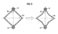
- FIG. 5 shows, as a section from FIG. 3 on the left, the diamond-like cross section of a single inlet channel with electrode 41, counterelectrode 42 and two axes 60 and 60 'which define a two-beam symmetry. These elements are important to the operability of the filter, with the electrodes 41 and 42 connected by the axis 60 as a line of symmetry.
- the described concept can be applied to other channel cross sections.
- the electrodes 41 and 42 and the connection axis 60 between the electrodes 41 and 42 are held as the first line of symmetry and deform the channel cross-section symmetrical with respect to this axis.
- the second line of symmetry results, for example, a star shape in the right area of Figure 5, in which the effective for the soot deposition wall surface in the inlet channel is increased compared to Figure 3.
- the outlet channels are complementarily deformed accordingly, so that again a complete covering of the cross section with inlet and outlet channels results.
- any transformation of a quadrilateral into an nx-square with n ⁇ 2 is possible.
Landscapes
- Chemical & Material Sciences (AREA)
- Engineering & Computer Science (AREA)
- Chemical Kinetics & Catalysis (AREA)
- Physics & Mathematics (AREA)
- Geometry (AREA)
- Combustion & Propulsion (AREA)
- General Engineering & Computer Science (AREA)
- Mechanical Engineering (AREA)
- General Chemical & Material Sciences (AREA)
- Analytical Chemistry (AREA)
- Environmental & Geological Engineering (AREA)
- Oil, Petroleum & Natural Gas (AREA)
- Biomedical Technology (AREA)
- Health & Medical Sciences (AREA)
- Physical Or Chemical Processes And Apparatus (AREA)
- Processes For Solid Components From Exhaust (AREA)
- Filtering Of Dispersed Particles In Gases (AREA)
- Amplifiers (AREA)
- Arc Welding In General (AREA)
- Sampling And Sample Adjustment (AREA)
Description
- Die Erfindung bezieht sich auf ein Plasma-Rußfilter gemäß dem Oberbegriff des Patentanspruches 1. Ein solcher Rußfilter ist Gegenstand der DE 100 57 862 C1.
- Mit vorgenanntem Patent wird ein Verfahren zur Verminderung kohlenstoffhaltiger Partikelemissionen von Dieselmotoren unter Schutz gestellt, bei dem die im Abgas enthaltenen Rußpartikel an Filteroberflächen abgeschieden werden, wobei zwecks Regeneration des Filters die abgeschiedenen Partikel oxidiert werden und die Regeneration durch nichtthermische, elektrische Oberflächengleitentladungen an den mit Rußpartikeln belegten Oberflächen erfolgt.
- In der DE 100 57 862 C1 sind verschiedene Geometrien zum Betrieb einer derartigen Anordnung beschrieben, die auf dem Prinzip von sogenannten Wandflussfiltern basieren. Diese Filter bestehen aus parallelen Kanälen mit viereckigem Querschnitt, die wechselseitig jeweils an der Auslassseite und an der Einlassseite des Abgases verschlossen sind. Dadurch ergibt sich eine Aufteilung in Einlasskanäle für das rußbeladene und Auslasskanäle für das gefilterte Abgas. Der Ruß wird auf den Innenwänden der einlassseitig offenen Kanäle abgeschieden und dort durch Sauerstoff- und Hydroxyl-Radikale oxidiert, die in unmittelbarer Wandnähe von nichtthermischen Oberflächengleitentladungs-Plasmen erzeugt werden.
- In der DE 100 57 862 C1 wird in naheliegender Weise davon ausgegangen, dass zur Erzeugung von Oberflächengleitentladungen in einem Filterkanal an jeder seiner Kanten eine Elektrode angebracht ist. Die zur Plasmaerzeugung erforderlichen Elektroden lassen sich dabei entweder in das Filtermaterial einbetten oder auf dem Filtermaterial so aufbringen, dass auf jeden Fall zwischen einer mit Hochspannung verbundenen Elektrode und der mit Masse verbundenen Gegenelektrode eine Schicht hoher dielektrischer Festigkeit liegt. Durch die dort beschriebene Einbettung der Elektroden lassen sich solche Oberflächengleitentladungen jedoch nur auf beiden Seiten der Zellwände generieren, während der Ruß nur auf einer Seite abgeschieden wird. Damit ist der spezifische Energieverbrauch für die Regeneration doppelt so hoch wie eigentlich erforderlich.
- Dem Abgas ausgesetzte Elektroden hingegen, die dort in Kombination mit eingebetteten Elektroden für den bevorzugten Betrieb von Oberflächengleitentladungen auf einer Seite der Wand vorgeschlagen werden, sind durch den Kontakt mit dem Abgas Erosionsprozessen ausgesetzt, die durch Gasentladungsprozesse noch verstärkt werden können. Diese Erosionsprozesse können nicht nur die Lebensdauer speziell der Elektroden, sondern über die Entstehung von Metalloxiden auch die Lebensdauer der Keramik beeinträchtigen.
- Ein weiterer Nachteil ist, dass die große Zahl der Elektroden - und zwar vier je Einlasskanal - Größe und Gewicht des Plasmarußfilters gegenüber einem herkömmlichen Filter wesentlich erhöht.
- Aus der Literatur sind Geometrien zum Betrieb dielektrisch behinderter Entladungen in keramischen Wabenkörpern bekannt (siehe z.B. EP 0 840 838 B1), in denen durch eine innenliegende Hochspannungs- und eine außenliegende Masseelektrode ein zylindrisches, viele Kanäle enthaltendes Volumen angeregt werden kann. Dadurch kann aber weder zwischen Ein- und Auslasskanälen eines Rußfilters differenziert werden, noch können gezielt Oberflächengleitentladungen erzeugt werden. Außerdem ist wegen der großen Schlagweite zwischen den Elektroden eine hohe Spannungsamplitude von über 20 kV erforderlich, die im Kraftfahrzeug zu Problemen führen kann.
- Ausgehend von letzterem Stand der Technik ist es Aufgabe der Erfindung, ein Plasma-Rußfilter anzugeben, bei dem durch eine geeignete Geometrie die oben angeführten Nachteile vermieden werden.
- Die Aufgabe ist erfindungsgemäß durch die Merkmale des Patentanspruches 1 gelöst. Weiterbildungen sind in den abhängigen Ansprüchen angegeben.
- Mit der Erfindung ist ein aus wechselseitig verschlossenen länglichen Kanälen mit beliebigem Querschnitt bestehender Wandflussfilter geschaffen, dessen mit Ruß belegte Wände durch Oberflächengleitentladungen regeneriert werden. Dabei brennen nunmehr die Oberflächengleitentladungen bedingt durch die Anordnung der in das Filtermaterial eingebetteten und damit vor Erosion geschützten Elektroden bevorzugt auf der mit Ruß belegten Einlassseite des Filters. Vorteilhafterweise werden bei der angegebenen Geometrie mit zweistrahliger Symmetrie pro Einlasskanal nur zwei Elektroden zur Erzeugung der Oberflächengleitentladungen benötigt.
- Ausgangspunkt der Erfindung ist ein aus matrixartig angeordneten länglichen Kanälen mit viereckigem Querschnitt bestehender Wandflussfilter. Die Kanäle sind längs einer Zeile oder einer Spalte wechselseitig verschlossenen, so dass sich Einlass- und Auslasskanäle abwechseln.
- Durch die erfindungsgemäße Elektrodenanordnung wird sichergestellt, dass die Verteilung des elektrischen Feldes in den einzelnen Zellen des Plasma-Rußfilters die Zündung von nichtthermischen Oberflächengleitentladungen in einzelnen Zellen ermöglicht. Dabei werden die dielektrischen Eigenschaften des Wandmaterials des keramischen Rußfilters ausgenutzt, die das Feld in Hohlräumen zwischen den Elektroden konzentriert. Überraschenderweise ergibt sich durch eine Verminderung der Elektrodenzahl pro Einlasskanal von 4 auf 2 nicht etwa eine Verschlechterung der elektrischen Feldverteilung hinsichtlich der Erzeugung von Oberflächengleitentladungen. Wesentlich dafür ist die Anordnung der Elektroden an diagonal gegenüberliegenden Kanten des viereckigen Kanalquerschnittes, wobei notwendigerweise über ihre nicht mit Elektroden versehenen Kanten benachbarte Einlasskanäle in gleicher Polarität beschaltet werden müssen.
- Weitere Einzelheiten und Vorteile der Erfindung ergeben sich aus der nachfolgenden Figurenbeschreibung von Ausführungsbeispielen anhand der Zeichnung in Verbindung mit den Patentansprüchen. Es zeigen
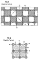
- Figur 1 und Figur 3 Querschnitte von Plasmafilterelementen mit Ein- und Auslasskanälen und zugehörigen Elektroden,
- Figur 2 und Figur 4 berechnete Feldstärkeverteilungen bei den Anordnungen gemäß Figur 1 und 3 sowie
- Figur 5 Querschnitte eines Einlasskanals mit zweistrahliger Symmetrie und dessen Variation.
- Die Figuren werden nachfolgend teilweise gemeinsam beschrieben. Insbesondere zu Figur 1 wird im Einzelnen auf die Patentschrift DE 100 57 862 C1 verwiesen.
- In letzterem Patent wird ein Verfahren und zugehörige Anordnungen zur Verminderung kohlenstoffhaltiger Partikelemissionen von Dieselmotoren unter Schutz gestellt, bei denen Oberflächengleitentladungen zum Einsatz kommen. In den in der DE 100 57 862 C1 im Einzelnen beschriebenen Figuren 1 bis 5 sowie 7 bis 12 sind Wandflussfilter aus keramischem Material aus wechselseitig verschlossenen länglichen Kanälen mit speziell viereckigem Querschnitt, in deren Eckpunkte jeweils Elektroden eingebaut sind, dargestellt.
- Figur 1 zeigt im Querschnitt eine derartige Elektrodenanordnung in einem Plasmafilterelement herkömmlicher Art mit vier in Filtermaterial eingebetteten Elektroden je Kanal.
- Im Einzelnen ist ein Einlaßkanal mit 10 und ein Auslasskanal mit 20 bezeichnet. Einlasskanal 10 und Auslasskanal 20 sind durch poröse Wände 30 aus spezifischem keramischen Material getrennt. In den Wänden 30 sind jeweils an den Kanten der Kanäle 10 Elektroden eingebaut, die jeweils paarweise nebeneinander als Hochspannungselektrode 41 und geerdete Elektrode 42 dienen. Um ausreichende dielektrische Festigkeit zu gewährleisten, sind die aus elektrisch leitfähigem Material gefertigten Elektroden 41 und 42 jeweils von einer elektrisch isolierenden Barrierenschicht 43 umgeben, die aus Gründen der Hochspannungsfestigkeit im Gegensatz zum Filtermaterial der Wände 30 niedrige Porosität aufweist.
- Figur 2 zeigt die für die Ausbildung von Oberflächengleitentladungen wichtige Verteilung der elektrischen Feldstärke für eine an den Hochspannungselektroden anliegende Spannung von 10 kV bei einem quadratischen Kanalquerschnitt von 2 x 2 mm2 im Querschnitt der Anordnung gemäß Figur 1. Mit 50 sind errechnete Feldminima in der Anordnung gemäß Figur 1 bezeichnet. Diese Minima finden sich aufgrund der quadrupolartigen Anordnung der Elektroden jeweils auf den Symmetrieachsen sowohl der Ein- als auch der Auslasskanäle. Bereiche erhöhter elektrischer Feldstärke 51, in denen elektrische Gasentladungen bevorzugt zünden werden, finden sich in der Nähe der Kanalwände sowohl der Ein- als auch der Auslasskanäle.
- Insgesamt ist aus Figur 2 erkennbar, dass sich aufgrund der Symmetrie in den Auslasskanälen 20 die gleiche elektrische Feldverteilung wie in den Einlasskanälen 10 ergibt. Zur Rußoxidation im Wandflussfilter werden aber die Bereiche erhöhter elektrischer Feldstärke tatsächlich nur in den Einlasskanälen benötigt.
- Figur 3 zeigt eine Elektrodenanordnung zur selektiven Erzeugung von Gasentladungen in den Einlasskanälen im Querschnitt. Wesentlicher Unterschied zu Figur 1 ist die rautenförmige Anordnung der Einlasskanäle 10 und der Auslasskanäle 20, welche sich aus einer Drehung der Struktur gemäß Figur 1 um 45° ergibt. Weiterer Unterschied zum Stand der Technik ist, dass an den nunmehr rautenförmig ausgebildeten Einlasskanälen jeweils in der Senkrechte an gegenüberliegenden Ecken der Raute Elektroden 40 vorhanden sind, die jeweils paarweise als Hochspannungselektrode 41 und als Masseelektrode 42 ausgeführt sind. Auch hier ist bei einem porösen Filtermaterial wieder eine Barrierenschicht 43 vorgesehen.
- Figur 4 zeigt die vorteilhafte Verteilung des elektrischen Feldes der Anordnung gemäß Figur 3, die die Zündung von Gasentladungen innerhalb der Einlasskanäle bevorzugt ermöglicht. Aus dieser berechneten Darstellung ergibt sich, dass im Vergleich zu Figur 2 die Einlasskanäle 10 über nahezu den gesamten Querschnitt eine erhöhte, für die Zündung von Gasentladungen ausreichende elektrische Feldstärke aufweisen, während in den Auslasskanälen 20 nur in Elektrodennähe aufgrund leicht erhöhter elektrischer Felder mit der Zündung von Gasentladungen zu rechnen ist. Ansonsten sind wieder Feldminima 50 entsprechend Figur 2 vorhanden.
- Bevorzugte Ansatzpunkte von Gasentladungen in den Einlasskanälen 10 liegen aufgrund der dort besonders stark erhöhten elektrischen Feldstärke zuerst in Elektrodennähe. Da während des Betriebes der Gasentladung dort jedoch elektrische Ladungsträger gespeichert werden und damit die elektrischen Felder dort reduziert werden, gleiten die bevorzugten Ansatzpunkte der Gasentladungen sukzessive auf den Wänden der Einlasskanäle 10 entlang in Richtung auf den Mittenbereich, bis die Wände soweit mit Oberflächenladungen belegt sind, dass keine weiteren Gasentladungen mehr gezündet werden können.
- Letzterer Prozess ist mit der Ausbildung von Oberflächengleitentladungen verbunden. Obwohl die anfängliche Feldverteilung Volumen- und Oberflächengleitentladungen gleichermaßen ermöglicht, wird auf diese Weise ein nicht unwesentlicher Teil der elektrischen Energie in Oberflächengleitentladungen umgesetzt. Gleichzeitig wird der Betrieb von Gasentladungen in den Auslasskanälen weitgehend unterdrückt. Damit wird bestätigt, dass mit der Anordnung gemäß Figur 3 ein gegenüber Figur 1, die dem Stand der Technik entspricht, verbessertes Ergebnis für die Realisierung eines Plasma-Russfilters mit Einsatz von Oberflächengleitentladungen zur Oxidation des Rußes vorliegt.
- Bei der Anordnung gemäß Figur 3 ergibt sich gegenüber Figur 1 nicht nur eine für die effiziente Nutzung der elektrischen Energie vorteilhafte elektrische Feldverteilung, sondern auch eine Verringerung des Material- und Kostenaufwandes durch reduzierte Elektrodenzahl pro Filtervolumen und -Fläche und gleichzeitig eine verringerte elektrische Kapazität, die sich durch vereinfachte Auslegung von Hochspannungsnetzteilen für die elektrische Anregung des Plasma-Rußfilters kostensenkend auswirkt. Wesentlich dafür ist die Anordnung der Elektroden an diagonal gegenüberliegenden Kanten des viereckigen Kanalquerschnittes, wobei über ihre nicht mit Elektroden versehenen Kanten benachbarte Einlasskanäle notwendigerweise in gleicher Polarität beschaltet werden müssen.
- Figur 5 zeigt als Ausschnitt aus Figur 3 links den rautenartigen Querschnitt eines einzelnen Einlasskanals mit Elektrode 41, Gegenelektrode 42 und zwei Achsen 60 und 60', die eine zweistrahlige Symmetrie definieren. Diese Elemente sind für Funktionsfähigkeit des Filters von Bedeutung, wobei die Elektroden 41 und 42 durch die Achse 60 als eine Symmetrielinie verbunden sind.
- Es ist offensichtlich, dass das beschriebene Konzept auf andere Kanalquerschnitte übertragbar ist. Ausgehend von der in Figur 3 gezeigten Gesamtgeometrie und der spezifischen Symmetrie gemäß Figur 5 hält man die Elektroden 41 und 42 sowie die Verbindungsachse 60 zwischen den Elektroden 41 und 42 als erste Symmetrielinie fest und verformt den Kanalquerschnitt symmetrisch bezüglich dieser Achse. Bei Berücksichtigung der zweiten Symmetrielinie ergibt sich beispielsweise eine Sternform im rechten Bereich von Figur 5, bei der die für die Rußablagerung wirksame Wandfläche im Einlasskanal gegenüber Figur 3 vergrößert ist.
- Berücksichtigt man die Geometrie entsprechend Figur 5, werden die Auslasskanäle komplementär entsprechend verformt, so dass sich wieder eine vollständige Bedeckung des Querschnittes mit Ein- und Auslasskanälen ergibt. Im Prinzip ist jede Umwandlung eines Vierecks in ein nxViereck mit n≥2 möglich.
Claims (8)
- Plasma-Rußfilter auf der Grundlage eines Wandflussfilters, bestehend aus wechselseitig verschlossenen länglichen Einlass- und Auslasskanälen aus keramischem Filtermaterial, wobei Rußpartikel an den Filteroberflächen der Einlasskanäle abgeschieden und dort zwecks Regeneration des Filters durch Einwirkung dielektrisch behinderter Oberflächengleitentladungen oxidiert werden, gekennzeichnet durch die Kombination folgender Merkmale:- die Kanäle (10, 20) haben einen Querschnitt mit zweistrahliger Symmetrie- zur Erzeugung der Oberflächengleitentladungen sind pro Einlasskanal (10) genau zwei Elektroden (41, 42) unterschiedlicher Polarität vorhanden, die auf einer der Symmetrielinien (60, 60') liegen.
- Plasma-Rußfilter nach Anspruch 1, dadurch gekennzeichnet, dass die Elektroden (41, 42) in das Filtermaterial (30) eingebettet und damit vor Erosion geschützt sind.
- Plasma-Rußfilter nach einem der vorhergehenden Ansprüche, dadurch gekennzeichnet , dass die Elektroden (41, 42) in ein elektrisch isolierendes Barrierenmaterial (43) niedriger Porosität eingebettet sind.
- Plasma-Rußfilter nach einem der vorhergehenden Ansprüche, dadurch gekennzeichnet , dass die Oberflächengleitentladungen selektiv auf der mit Ruß belegten Einlassseite des Wandflussfilters mit Einlasskanal (10) und Auslasskanal (20) brennen.
- Plasma-Rußfilter nach einem der vorhergehenden Ansprüche, dadurch gekennzeichnet , dass die Kanäle (10, 20) mit ihrem Querschnitt in zweistrahliger Symmetrie eine Viereckgeometrie haben, wobei die beiden Elektroden (41, 42) an gegenüberliegenden Ecken der Viereckgeometrie angeordnet sind.
- Plasma-Rußfilter nach Anspruch 5, dadurch gekennzeichnet, dass die Viereckgeometrie eine vertikal orientierte Raute ist.
- Plasma-Rußfilter nach Anspruch 6, wobei Elektroden an diagonal gegenüberliegenden Ecken von mehreren benachbarten rautenförmigen Kanalquerschnitten angeordnet sind, dadurch gekennzeichnet , dass die Elektroden (41, 42) an den Ecken benachbarter Einlasskanäle (10) in gleicher Polarität beschaltet sind.
- Plasma-Rußfilter nach einem der Ansprüche 1 bis 5, dadurch gekennzeichnet , dass der Querschnitt des Einlasskanals (10) mit zweistrahliger Geometrie eine (nx4)-eckige Geometrie mit n≥2 hat, die durch Verformung des viereckförmigen Querschnitts des Einlasskanals (10) bei Festhalten der Elektroden (41, 42) und der ersten Symmetrielinie (60) erhalten wird (Fig. 5).
Applications Claiming Priority (3)
| Application Number | Priority Date | Filing Date | Title |
|---|---|---|---|
| DE10229881 | 2002-07-03 | ||
| DE10229881A DE10229881B4 (de) | 2002-07-03 | 2002-07-03 | Plasma-Russfilter |
| PCT/DE2003/002187 WO2004004869A1 (de) | 2002-07-03 | 2003-07-01 | Plasma-russfilter |
Publications (2)
| Publication Number | Publication Date |
|---|---|
| EP1517737A1 EP1517737A1 (de) | 2005-03-30 |
| EP1517737B1 true EP1517737B1 (de) | 2006-11-22 |
Family
ID=29723667
Family Applications (1)
| Application Number | Title | Priority Date | Filing Date |
|---|---|---|---|
| EP03762434A Expired - Lifetime EP1517737B1 (de) | 2002-07-03 | 2003-07-01 | Plasma-russfilter |
Country Status (7)
| Country | Link |
|---|---|
| US (1) | US7326264B2 (de) |
| EP (1) | EP1517737B1 (de) |
| JP (1) | JP4522854B2 (de) |
| AT (1) | ATE345863T1 (de) |
| DE (2) | DE10229881B4 (de) |
| ES (1) | ES2277117T3 (de) |
| WO (1) | WO2004004869A1 (de) |
Families Citing this family (13)
| Publication number | Priority date | Publication date | Assignee | Title |
|---|---|---|---|---|
| FR2867510B1 (fr) * | 2004-03-11 | 2006-10-20 | Peugeot Citroen Automobiles Sa | Systeme de purification des gaz d'echappement d'un moteur thermique de vehicule automobile et ligne d'echappement comportant un tel systeme |
| FR2883199B1 (fr) * | 2005-03-18 | 2007-06-22 | Peugeot Citroen Automobiles Sa | Filtre a particules pour vehicule automobile et systeme et ligne d'echappement comprenant un tel filtre a particules |
| JP3897798B2 (ja) * | 2005-06-08 | 2007-03-28 | 日新電機株式会社 | 排ガス浄化方法及び排ガス浄化装置 |
| GB2429417B (en) * | 2005-08-25 | 2010-08-11 | Perkins Engines Co Ltd | Autoselective regenerating particulate filter |
| US7685814B2 (en) * | 2006-07-12 | 2010-03-30 | Cummins Filtration, Inc. | Systems, apparatuses, and methods of determining plugging or deplugging of a diesel oxidation catalyst device |
| US8252077B2 (en) * | 2007-09-17 | 2012-08-28 | GM Global Technology Operations LLC | Electrically heated particulate filter heater insulation |
| JP2009137212A (ja) * | 2007-12-07 | 2009-06-25 | Toyota Industries Corp | 排気ガスのプラズマ処理装置の製造方法 |
| US8747502B2 (en) * | 2008-02-25 | 2014-06-10 | Industry-Academic Cooperation Foundation, Jeju National University | Particulate matter reduction apparatus for diesel engine |
| WO2010037406A1 (en) * | 2008-09-30 | 2010-04-08 | Perkins Engines Company Limited | Method and apparatus for regenerating a filter |
| DE102009019744A1 (de) * | 2009-05-02 | 2011-04-14 | Hydac Filtertechnik Gmbh | Filtervorrichtung zum Reinigen von Fluiden |
| US20230285630A1 (en) * | 2014-02-18 | 2023-09-14 | University Of South Australia | Plasma hydrogel therapy |
| US20180306743A1 (en) * | 2015-11-26 | 2018-10-25 | Kyocera Corporation | Particulate matter measuring device component, and manufacturing method therefor |
| JPWO2018012421A1 (ja) * | 2016-07-12 | 2019-06-13 | 日本碍子株式会社 | 微粒子数検出器 |
Family Cites Families (19)
| Publication number | Priority date | Publication date | Assignee | Title |
|---|---|---|---|---|
| DE3608801A1 (de) * | 1986-03-15 | 1987-09-17 | Fev Forsch Energietech Verbr | Verfahren und vorrichtung zur regeneration von partikelfiltersystemen |
| US5207807A (en) * | 1986-12-05 | 1993-05-04 | Iveco Fiat S.P.A. | Regenerable filter for exhaust gases of an internal-combustion engine |
| DE3705979A1 (de) * | 1987-02-25 | 1988-09-08 | Navsat Gmbh | Abgasrussfilter |
| DE3715174A1 (de) * | 1987-05-07 | 1988-11-24 | Christian Bergemann | Verfahren zur regeneration russbehafteter flaechen und filter aus keramischen oder mineralischen werkstoffen oder beschichtungen |
| JPH0227107A (ja) * | 1988-07-18 | 1990-01-29 | Nafuzato Gmbh | 排気ガスすすフィルタ |
| DE4230631C2 (de) * | 1992-09-12 | 1996-08-08 | Amann & Soehne | Verfahren zur Entfernung von elektrisch leitenden Teilchen aus einem Gasstrom sowie Vorrichtung zur Durchführung des Verfahrens |
| JPH06146852A (ja) * | 1992-11-13 | 1994-05-27 | Senichi Masuda | デイーゼルエンジン排気ガス浄化装置 |
| WO1997005369A1 (de) * | 1995-07-27 | 1997-02-13 | Fleck Carl M | Verfahren und vorrichtung zur zerlegung von stickstoffoxiden in abgasen von verbrennungsmotoren |
| US5827407A (en) * | 1996-08-19 | 1998-10-27 | Raytheon Company | Indoor air pollutant destruction apparatus and method using corona discharge |
| GB9803817D0 (en) * | 1998-02-25 | 1998-04-22 | Aea Technology Plc | A component for gas treatment |
| GB2351923A (en) * | 1999-07-12 | 2001-01-17 | Perkins Engines Co Ltd | Self-cleaning particulate filter utilizing electric discharge currents |
| JP4281186B2 (ja) * | 1999-12-15 | 2009-06-17 | 株式会社豊田中央研究所 | 放電再生式捕集フィルタ |
| DE10003816A1 (de) * | 2000-01-28 | 2001-08-02 | Opel Adam Ag | Regenerierbarer Partikelfilter zum Entfernen von Rußpartikeln aus Abgasen |
| JP2001276561A (ja) * | 2000-03-31 | 2001-10-09 | Ngk Insulators Ltd | ハニカム構造体を具える放電装置 |
| JP2001349215A (ja) * | 2000-06-08 | 2001-12-21 | Hideo Kawamura | Noxを吸着材に付着させて分解する排気ガス浄化装置 |
| DE10130163B4 (de) * | 2000-11-21 | 2012-01-12 | Siemens Ag | Anordnung zur Verminderung kohlenstoffhaltiger Partikelemissionen von Dieselmotoren |
| DE10057862C5 (de) * | 2000-11-21 | 2004-05-06 | Siemens Ag | Verfahren zur Verminderung kohlenstoffhaltiger Partikelemissionen von Dieselmotoren und zugehörige Anordnung |
| FR2842389B1 (fr) * | 2002-07-09 | 2004-08-20 | Physiques Ecp Et Chimiques | Dispositif modulaire pour generer de multiples decharges electriques glissantes de haute tension |
| JP2004340049A (ja) * | 2003-05-16 | 2004-12-02 | Hino Motors Ltd | 排気浄化装置 |
-
2002
- 2002-07-03 DE DE10229881A patent/DE10229881B4/de not_active Expired - Fee Related
-
2003
- 2003-07-01 US US10/522,853 patent/US7326264B2/en not_active Expired - Fee Related
- 2003-07-01 AT AT03762434T patent/ATE345863T1/de not_active IP Right Cessation
- 2003-07-01 EP EP03762434A patent/EP1517737B1/de not_active Expired - Lifetime
- 2003-07-01 ES ES03762434T patent/ES2277117T3/es not_active Expired - Lifetime
- 2003-07-01 JP JP2004518423A patent/JP4522854B2/ja not_active Expired - Fee Related
- 2003-07-01 WO PCT/DE2003/002187 patent/WO2004004869A1/de not_active Ceased
- 2003-07-01 DE DE50305763T patent/DE50305763D1/de not_active Expired - Lifetime
Also Published As
| Publication number | Publication date |
|---|---|
| EP1517737A1 (de) | 2005-03-30 |
| US20060010843A1 (en) | 2006-01-19 |
| US7326264B2 (en) | 2008-02-05 |
| DE10229881A1 (de) | 2004-01-15 |
| JP4522854B2 (ja) | 2010-08-11 |
| JP2005531401A (ja) | 2005-10-20 |
| DE10229881B4 (de) | 2008-01-31 |
| WO2004004869A1 (de) | 2004-01-15 |
| ATE345863T1 (de) | 2006-12-15 |
| DE50305763D1 (de) | 2007-01-04 |
| ES2277117T3 (es) | 2007-07-01 |
Similar Documents
| Publication | Publication Date | Title |
|---|---|---|
| EP1336032B1 (de) | Verfahren zur verminderung kohlenstoffhaltiger partikelemissionen von dieselmotoren und zugehörige anordnung | |
| DE10229881B4 (de) | Plasma-Russfilter | |
| DE102014110789A1 (de) | Gasreformierungsvorrichtung, Abgasreinigungssystem und Luftreiniger | |
| DE19534950C2 (de) | Vorrichtung zur plasmachemischen Zersetzung und/oder Vernichtung von Schadstoffen | |
| DE10057862C5 (de) | Verfahren zur Verminderung kohlenstoffhaltiger Partikelemissionen von Dieselmotoren und zugehörige Anordnung | |
| EP2477749B1 (de) | VORRICHTUNG UND VERFAHREN ZUR BEHANDLUNG VON RUßPARTIKEL ENTHALTENDEM ABGAS | |
| DE19518970C1 (de) | Verfahren und Vorrichtung zur Behandlung von Abgas | |
| DE69904447T2 (de) | Gasbehandlungskomponente | |
| EP2477748B1 (de) | Vorrichtung zur behandlung von russpartikel enthaltendem abgas | |
| AT409653B (de) | Verfahren und vorrichtung zum abscheiden von russpartikel aus einem abgasstrom, insbesondere einer diesel-brennkraftmaschine | |
| DE60320090T2 (de) | Reaktor zur plasmabehandlung eines gasstroms insbesondere von abgasen aus einem verbrennungsmotor eines kraftfahrzeugs | |
| EP1375851A1 (de) | Plasmareaktor, Verfahren zu dessen Herstellung und Einrichtung zur Behandlung von Abgasen in Verbrennungsmotoren | |
| AT501888B1 (de) | Wabenfilter mit planaren elektroden | |
| DE10344489B4 (de) | Vorrichtung und Verfahren zur Ausfilterung von Ruß aus Abgasen oder Aerosolen aus Abluft und zur plasmagestützten Behandlung von Abgas oder von Abluft | |
| DE102005034033A1 (de) | Verfahren und Vorrichtung zur Verminderung des Partikelanteils in Abgasen | |
| DE60210557T2 (de) | Vorrichtung zur Abgasbehandlung einer Brennkraftmaschine | |
| EP0840838B1 (de) | Verfahren und vorrichtung zur zerlegung von stickstoffoxiden in abgasen von verbrennungsmotoren | |
| EP2616181B1 (de) | Vorrichtung zur erzeugung eines elektrischen feldes in einem abgassystem | |
| AT501876B1 (de) | Verfahren und vorrichtung zum abbau von stickstoffoxiden in einem abgasstrom | |
| WO2006128711A1 (de) | Verfahren und vorrichtung zur verminderung des partikelanteils in abgasen | |
| DE19504138A1 (de) | Abgasreinigungsmodul und Verfahren zu seiner Herstellung | |
| DE102010034250A1 (de) | Halterung für zumindest eine Elektrode in einer Abgasleitung |
Legal Events
| Date | Code | Title | Description |
|---|---|---|---|
| PUAI | Public reference made under article 153(3) epc to a published international application that has entered the european phase |
Free format text: ORIGINAL CODE: 0009012 |
|
| 17P | Request for examination filed |
Effective date: 20041207 |
|
| AK | Designated contracting states |
Kind code of ref document: A1 Designated state(s): AT BE BG CH CY CZ DE DK EE ES FI FR GB GR HU IE IT LI LU MC NL PT RO SE SI SK TR |
|
| GRAP | Despatch of communication of intention to grant a patent |
Free format text: ORIGINAL CODE: EPIDOSNIGR1 |
|
| GRAS | Grant fee paid |
Free format text: ORIGINAL CODE: EPIDOSNIGR3 |
|
| GRAA | (expected) grant |
Free format text: ORIGINAL CODE: 0009210 |
|
| AK | Designated contracting states |
Kind code of ref document: B1 Designated state(s): AT BE BG CH CY CZ DE DK EE ES FI FR GB GR HU IE IT LI LU MC NL PT RO SE SI SK TR |
|
| PG25 | Lapsed in a contracting state [announced via postgrant information from national office to epo] |
Ref country code: RO Free format text: LAPSE BECAUSE OF FAILURE TO SUBMIT A TRANSLATION OF THE DESCRIPTION OR TO PAY THE FEE WITHIN THE PRESCRIBED TIME-LIMIT Effective date: 20061122 Ref country code: FI Free format text: LAPSE BECAUSE OF FAILURE TO SUBMIT A TRANSLATION OF THE DESCRIPTION OR TO PAY THE FEE WITHIN THE PRESCRIBED TIME-LIMIT Effective date: 20061122 Ref country code: SI Free format text: LAPSE BECAUSE OF FAILURE TO SUBMIT A TRANSLATION OF THE DESCRIPTION OR TO PAY THE FEE WITHIN THE PRESCRIBED TIME-LIMIT Effective date: 20061122 Ref country code: NL Free format text: LAPSE BECAUSE OF FAILURE TO SUBMIT A TRANSLATION OF THE DESCRIPTION OR TO PAY THE FEE WITHIN THE PRESCRIBED TIME-LIMIT Effective date: 20061122 |
|
| REG | Reference to a national code |
Ref country code: GB Ref legal event code: FG4D Free format text: NOT ENGLISH |
|
| REG | Reference to a national code |
Ref country code: CH Ref legal event code: EP |
|
| REG | Reference to a national code |
Ref country code: IE Ref legal event code: FG4D Free format text: LANGUAGE OF EP DOCUMENT: GERMAN |
|
| REF | Corresponds to: |
Ref document number: 50305763 Country of ref document: DE Date of ref document: 20070104 Kind code of ref document: P |
|
| PG25 | Lapsed in a contracting state [announced via postgrant information from national office to epo] |
Ref country code: DK Free format text: LAPSE BECAUSE OF FAILURE TO SUBMIT A TRANSLATION OF THE DESCRIPTION OR TO PAY THE FEE WITHIN THE PRESCRIBED TIME-LIMIT Effective date: 20070222 Ref country code: SE Free format text: LAPSE BECAUSE OF FAILURE TO SUBMIT A TRANSLATION OF THE DESCRIPTION OR TO PAY THE FEE WITHIN THE PRESCRIBED TIME-LIMIT Effective date: 20070222 Ref country code: BG Free format text: LAPSE BECAUSE OF FAILURE TO SUBMIT A TRANSLATION OF THE DESCRIPTION OR TO PAY THE FEE WITHIN THE PRESCRIBED TIME-LIMIT Effective date: 20070222 |
|
| GBT | Gb: translation of ep patent filed (gb section 77(6)(a)/1977) |
Effective date: 20070226 |
|
| PG25 | Lapsed in a contracting state [announced via postgrant information from national office to epo] |
Ref country code: PT Free format text: LAPSE BECAUSE OF FAILURE TO SUBMIT A TRANSLATION OF THE DESCRIPTION OR TO PAY THE FEE WITHIN THE PRESCRIBED TIME-LIMIT Effective date: 20070423 |
|
| NLV1 | Nl: lapsed or annulled due to failure to fulfill the requirements of art. 29p and 29m of the patents act | ||
| ET | Fr: translation filed | ||
| REG | Reference to a national code |
Ref country code: ES Ref legal event code: FG2A Ref document number: 2277117 Country of ref document: ES Kind code of ref document: T3 |
|
| PLBE | No opposition filed within time limit |
Free format text: ORIGINAL CODE: 0009261 |
|
| STAA | Information on the status of an ep patent application or granted ep patent |
Free format text: STATUS: NO OPPOSITION FILED WITHIN TIME LIMIT |
|
| 26N | No opposition filed |
Effective date: 20070823 |
|
| REG | Reference to a national code |
Ref country code: CH Ref legal event code: PL |
|
| PG25 | Lapsed in a contracting state [announced via postgrant information from national office to epo] |
Ref country code: GR Free format text: LAPSE BECAUSE OF FAILURE TO SUBMIT A TRANSLATION OF THE DESCRIPTION OR TO PAY THE FEE WITHIN THE PRESCRIBED TIME-LIMIT Effective date: 20070223 Ref country code: MC Free format text: LAPSE BECAUSE OF NON-PAYMENT OF DUE FEES Effective date: 20070731 Ref country code: CH Free format text: LAPSE BECAUSE OF NON-PAYMENT OF DUE FEES Effective date: 20070731 Ref country code: LI Free format text: LAPSE BECAUSE OF NON-PAYMENT OF DUE FEES Effective date: 20070731 |
|
| PG25 | Lapsed in a contracting state [announced via postgrant information from national office to epo] |
Ref country code: AT Free format text: LAPSE BECAUSE OF NON-PAYMENT OF DUE FEES Effective date: 20070701 |
|
| PG25 | Lapsed in a contracting state [announced via postgrant information from national office to epo] |
Ref country code: EE Free format text: LAPSE BECAUSE OF FAILURE TO SUBMIT A TRANSLATION OF THE DESCRIPTION OR TO PAY THE FEE WITHIN THE PRESCRIBED TIME-LIMIT Effective date: 20061122 |
|
| PG25 | Lapsed in a contracting state [announced via postgrant information from national office to epo] |
Ref country code: LU Free format text: LAPSE BECAUSE OF NON-PAYMENT OF DUE FEES Effective date: 20070701 Ref country code: CY Free format text: LAPSE BECAUSE OF FAILURE TO SUBMIT A TRANSLATION OF THE DESCRIPTION OR TO PAY THE FEE WITHIN THE PRESCRIBED TIME-LIMIT Effective date: 20061122 |
|
| PG25 | Lapsed in a contracting state [announced via postgrant information from national office to epo] |
Ref country code: TR Free format text: LAPSE BECAUSE OF FAILURE TO SUBMIT A TRANSLATION OF THE DESCRIPTION OR TO PAY THE FEE WITHIN THE PRESCRIBED TIME-LIMIT Effective date: 20061122 Ref country code: HU Free format text: LAPSE BECAUSE OF FAILURE TO SUBMIT A TRANSLATION OF THE DESCRIPTION OR TO PAY THE FEE WITHIN THE PRESCRIBED TIME-LIMIT Effective date: 20070523 |
|
| PGFP | Annual fee paid to national office [announced via postgrant information from national office to epo] |
Ref country code: DE Payment date: 20140919 Year of fee payment: 12 |
|
| REG | Reference to a national code |
Ref country code: FR Ref legal event code: PLFP Year of fee payment: 13 |
|
| PGFP | Annual fee paid to national office [announced via postgrant information from national office to epo] |
Ref country code: SK Payment date: 20150630 Year of fee payment: 13 |
|
| PGFP | Annual fee paid to national office [announced via postgrant information from national office to epo] |
Ref country code: GB Payment date: 20150709 Year of fee payment: 13 Ref country code: IE Payment date: 20150723 Year of fee payment: 13 Ref country code: CZ Payment date: 20150630 Year of fee payment: 13 Ref country code: ES Payment date: 20150807 Year of fee payment: 13 |
|
| PGFP | Annual fee paid to national office [announced via postgrant information from national office to epo] |
Ref country code: BE Payment date: 20150721 Year of fee payment: 13 Ref country code: FR Payment date: 20150715 Year of fee payment: 13 |
|
| PGFP | Annual fee paid to national office [announced via postgrant information from national office to epo] |
Ref country code: IT Payment date: 20150727 Year of fee payment: 13 |
|
| REG | Reference to a national code |
Ref country code: DE Ref legal event code: R119 Ref document number: 50305763 Country of ref document: DE |
|
| PG25 | Lapsed in a contracting state [announced via postgrant information from national office to epo] |
Ref country code: DE Free format text: LAPSE BECAUSE OF NON-PAYMENT OF DUE FEES Effective date: 20160202 |
|
| PG25 | Lapsed in a contracting state [announced via postgrant information from national office to epo] |
Ref country code: BE Free format text: LAPSE BECAUSE OF NON-PAYMENT OF DUE FEES Effective date: 20160731 |
|
| PG25 | Lapsed in a contracting state [announced via postgrant information from national office to epo] |
Ref country code: CZ Free format text: LAPSE BECAUSE OF NON-PAYMENT OF DUE FEES Effective date: 20160701 |
|
| GBPC | Gb: european patent ceased through non-payment of renewal fee |
Effective date: 20160701 |
|
| REG | Reference to a national code |
Ref country code: SK Ref legal event code: MM4A Ref document number: E 1489 Country of ref document: SK Effective date: 20160701 |
|
| PG25 | Lapsed in a contracting state [announced via postgrant information from national office to epo] |
Ref country code: FR Free format text: LAPSE BECAUSE OF NON-PAYMENT OF DUE FEES Effective date: 20160801 |
|
| REG | Reference to a national code |
Ref country code: FR Ref legal event code: ST Effective date: 20170331 |
|
| REG | Reference to a national code |
Ref country code: IE Ref legal event code: MM4A |
|
| PG25 | Lapsed in a contracting state [announced via postgrant information from national office to epo] |
Ref country code: SK Free format text: LAPSE BECAUSE OF NON-PAYMENT OF DUE FEES Effective date: 20160701 Ref country code: GB Free format text: LAPSE BECAUSE OF NON-PAYMENT OF DUE FEES Effective date: 20160701 |
|
| PG25 | Lapsed in a contracting state [announced via postgrant information from national office to epo] |
Ref country code: IE Free format text: LAPSE BECAUSE OF NON-PAYMENT OF DUE FEES Effective date: 20160701 |
|
| PG25 | Lapsed in a contracting state [announced via postgrant information from national office to epo] |
Ref country code: IT Free format text: LAPSE BECAUSE OF NON-PAYMENT OF DUE FEES Effective date: 20160701 |
|
| PG25 | Lapsed in a contracting state [announced via postgrant information from national office to epo] |
Ref country code: ES Free format text: LAPSE BECAUSE OF NON-PAYMENT OF DUE FEES Effective date: 20160702 |
|
| REG | Reference to a national code |
Ref country code: ES Ref legal event code: FD2A Effective date: 20181203 |