EP1517409A2 - Winkelstecker für hohe Frequenzen - Google Patents
Winkelstecker für hohe Frequenzen Download PDFInfo
- Publication number
- EP1517409A2 EP1517409A2 EP04017765A EP04017765A EP1517409A2 EP 1517409 A2 EP1517409 A2 EP 1517409A2 EP 04017765 A EP04017765 A EP 04017765A EP 04017765 A EP04017765 A EP 04017765A EP 1517409 A2 EP1517409 A2 EP 1517409A2
- Authority
- EP
- European Patent Office
- Prior art keywords
- longitudinal
- dielectric
- transverse
- right angle
- receiving chamber
- Prior art date
- Legal status (The legal status is an assumption and is not a legal conclusion. Google has not performed a legal analysis and makes no representation as to the accuracy of the status listed.)
- Withdrawn
Links
- 239000004020 conductor Substances 0.000 claims 2
- 239000003989 dielectric material Substances 0.000 description 3
- 238000005476 soldering Methods 0.000 description 2
- 229920006362 Teflon® Polymers 0.000 description 1
- 238000010276 construction Methods 0.000 description 1
- 238000002347 injection Methods 0.000 description 1
- 239000007924 injection Substances 0.000 description 1
- 230000013011 mating Effects 0.000 description 1
- 238000000034 method Methods 0.000 description 1
- 230000004048 modification Effects 0.000 description 1
- 238000012986 modification Methods 0.000 description 1
- 239000004033 plastic Substances 0.000 description 1
- 238000007789 sealing Methods 0.000 description 1
Images


Classifications
-
- H—ELECTRICITY
- H01—ELECTRIC ELEMENTS
- H01R—ELECTRICALLY-CONDUCTIVE CONNECTIONS; STRUCTURAL ASSOCIATIONS OF A PLURALITY OF MUTUALLY-INSULATED ELECTRICAL CONNECTING ELEMENTS; COUPLING DEVICES; CURRENT COLLECTORS
- H01R24/00—Two-part coupling devices, or either of their cooperating parts, characterised by their overall structure
- H01R24/38—Two-part coupling devices, or either of their cooperating parts, characterised by their overall structure having concentrically or coaxially arranged contacts
- H01R24/40—Two-part coupling devices, or either of their cooperating parts, characterised by their overall structure having concentrically or coaxially arranged contacts specially adapted for high frequency
- H01R24/50—Two-part coupling devices, or either of their cooperating parts, characterised by their overall structure having concentrically or coaxially arranged contacts specially adapted for high frequency mounted on a PCB [Printed Circuit Board]
-
- H—ELECTRICITY
- H01—ELECTRIC ELEMENTS
- H01R—ELECTRICALLY-CONDUCTIVE CONNECTIONS; STRUCTURAL ASSOCIATIONS OF A PLURALITY OF MUTUALLY-INSULATED ELECTRICAL CONNECTING ELEMENTS; COUPLING DEVICES; CURRENT COLLECTORS
- H01R2103/00—Two poles
Definitions
- This invention relates to electrical connectors and more particularly to high frequency right angle connectors.
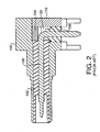
- High frequency right angle connectors C shown in Figs. 1 and 2 are known and a previous type was composed of a die cast body 100, three Teflon® screw machine dielectrics, 102, 104 and 106, a contact 108 and a die cast cap 110.
- the contact 108 was press-fitted into one of the dielectrics 102 to form a sub-assembly, which was then inserted into the die cast body 100.
- a second dielectric 104 was then placed over the comer of the contact 108.
- the third dielectric 106 was then placed over the short end of the contact 108 and pressed into an opening in the die cast body 100.
- the die cast cap 110 was then seated into the body 100 to complete the assembly.
- This structure does not provide adequate shielding because of the gap 120 that exists at the bend of the contact 108.
- the gap extends completely around the bend.
- the short dielectric 106 has no stop feature to prevent it from being pushed too far into the die cast body. Therefore, the true position of the contact 108 was determined by the fit of the pin into the dielectric and the associated tolerances of each component. These conditions proved unacceptable for the use of the connector.
- a high frequency, right angle socket comprising a body including a longitudinal bore extending completely through the body and a transverse bore intersecting the longitudinal bore.
- a first dielectric is formed to frictionally engage the longitudinal bore, the dielectric having a proximal end and a distal end and including a longitudinal electric contact-receiving chamber.
- a right angle electrical contact has a longitudinal portion and a transverse portion, the longitudinal portion including a first contact retainer.
- the transverse portion has a second contact retainer.
- the longitudinal portion is fitted into the longitudinal electrical contact-receiving chamber of the first dielectric with the contact retainer on the longitudinal portion engaging the interior wall of the longitudinal contact-receiving chamber.
- a second dielectric is formed to frictionally engage the transverse bore and includes a transverse electrical contact-receiving chamber.
- the transverse portion of the right angle electrical contact is fitted into the transverse electrical contact-receiving chamber with the contact retainer on the transverse portion engaging the interior wall of the transverse electrical receiving chamber.
- a cap closes one end of the longitudinal bore.
- This construction provides fewer components and makes easier the correct positioning of the contact pin for both its mating end (the long portion) and the circuit board end (the short end). Shielding is effected by completely eliminating the gap around the bend of the contact pin. The cap is coined into place thus ensuring that it will remain in place during a soldering process.
- Fig. 1 is an exploded perspective view of a prior art connector
- Fig. 2 is a longitudinal sectional view of the connector of Fig. 1;
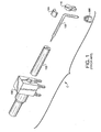
- Fig. 3 is an exploded perspective view of an embodiment of the invention.
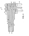
- Fig. 4 is a longitudinal sectional view of the connector of Fig. 3;
- Fig. 5 is a longitudinal sectional view of the connector body alone.
- a high frequency, right angle socket 10 comprising a body 12 including a longitudinal bore 14 extending completely through the body 12 and a transverse bore 16 intersecting the longitudinal bore 14.
- the bores 14 and 16 are seen most clearly in Fig. 5.
- a first dielectric18 is formed to frictionally engage the longitudinal bore 14.
- the dielectric 18 has a proximal end 20 and a distal end 22 and includes a longitudinal electric contact-receiving chamber 24.
- a right angle electrical contact 26 has a longitudinal portion 28 and a transverse portion 30.
- the longitudinal portion 28 includes a first contact retainer 32.
- the transverse portion 30 includes a contact retainer 33.
- the longitudinal portion 28 is fitted into the longitudinal electrical contact-receiving chamber 24 of the first dielectric 18 with the contact retainer 32 on the longitudinal portion 28 engaging the interior wall of the longitudinal contact-receiving chamber 24.
- a second dielectric 34 is formed to frictionally engage the transverse bore 16 and includes a transverse electrical contact-receiving chamber 36.
- the transverse portion 30 of the right angle electrical contact 26 is fitted into the transverse electrical contact-receiving chamber 36 with the contact retainer 33 on the transverse portion 30 engaging the interior wall of the transverse electrical contact-receiving chamber 36.
- a cap 38 closes one end of the longitudinal bore 14.
- the distal end 22 of the first dielectric 18 includes an external shoulder 40 that engages an internal shoulder 42 (see Fig. 5) formed in the longitudinal bore 14.
- the second dielectric 34 includes a chamfered end 44 that engages a chamfered edge 46 at the terminus of the transverse bore 16.
- the distal end 22 of the first dielectric 18 also includes an alignment slot 46 that fittingly receives an alignment tab 48 formed on the second dielectric 34 and the proximal end 20 of the first dielectric 18 has a cup-shaped depression 50 formed for a portion of its length to receive a connecting member.
- the longitudinal portion 28 of the contact 26 is press-fitted into the first dielectric 18 to form a sub-assembly, which is then inserted into the die cast body 12.
- the contact retainer 32 engages the interior surface of the longitudinal bore 14 to fix the position of the contact.
- the second dielectric 34 is then placed upon the transverse portion 30 of the electrical contact 26 and inserted until contact is made between the chamfered end 44 of the second dielectric 34 and the chamfered edge 46 of the transverse bore 16.
- the alignment tab 48 fills the alignment slot 46 formed in the distal end 22 of the first dielectric 18 completely sealing the contact 26 to achieve adequate shielding.
- the die cast cap 38 is then seated into the body 12 and coined into place, thus completing the assembly.
- the dielectrics 18 and 34 are preferably plastic injection to accommodate the complex shapes.
- mounting posts 52 are round as opposed to square, as was the case with the prior connector, to provide improved soldering with the printed circuit board to which the connector 10 is mounted.
Landscapes
- Connector Housings Or Holding Contact Members (AREA)
- Coupling Device And Connection With Printed Circuit (AREA)
Applications Claiming Priority (4)
| Application Number | Priority Date | Filing Date | Title |
|---|---|---|---|
| US50361903P | 2003-09-17 | 2003-09-17 | |
| US503619P | 2003-09-17 | ||
| US737303 | 2003-12-16 | ||
| US10/737,303 US6905364B2 (en) | 2003-09-17 | 2003-12-16 | High frequency right angle connector |
Publications (1)
| Publication Number | Publication Date |
|---|---|
| EP1517409A2 true EP1517409A2 (de) | 2005-03-23 |
Family
ID=34198305
Family Applications (1)
| Application Number | Title | Priority Date | Filing Date |
|---|---|---|---|
| EP04017765A Withdrawn EP1517409A2 (de) | 2003-09-17 | 2004-07-27 | Winkelstecker für hohe Frequenzen |
Country Status (4)
| Country | Link |
|---|---|
| US (1) | US6905364B2 (de) |
| EP (1) | EP1517409A2 (de) |
| KR (1) | KR20050028317A (de) |
| CA (1) | CA2475645A1 (de) |
Cited By (2)
| Publication number | Priority date | Publication date | Assignee | Title |
|---|---|---|---|---|
| EP3869631A1 (de) * | 2020-02-18 | 2021-08-25 | ERICH JAEGER GmbH + Co. KG | Daten-steckverbindungsadapter für eine datenübertragung und kraftfahrzeugsteckdose mit daten-steckverbindungsadapter |
| EP3714514B1 (de) * | 2017-11-21 | 2022-12-07 | Phoenix Contact GmbH & Co KG | Steckverbinder |
Families Citing this family (9)
| Publication number | Priority date | Publication date | Assignee | Title |
|---|---|---|---|---|
| JP2009153239A (ja) * | 2007-12-18 | 2009-07-09 | Sumitomo Wiring Syst Ltd | 電気接続箱 |
| US20160284442A1 (en) * | 2015-03-24 | 2016-09-29 | Fujitsu Limited | Coaxial cable |
| US9691525B2 (en) | 2015-03-24 | 2017-06-27 | Fujitsu Limited | Coaxial cable |
| KR101626731B1 (ko) * | 2015-12-08 | 2016-06-13 | 한국씨티에스주식회사 | 전원선과 열선을 연결하는 연결 장치 |
| JP6588403B2 (ja) * | 2016-08-09 | 2019-10-09 | ヒロセ電機株式会社 | 同軸コネクタ |
| EP3884547B1 (de) * | 2018-11-20 | 2025-05-07 | Corning Optical Communications RF LLC | Rechtwinkliges koaxialkabel zum pcb verbinder |
| CN109687195B (zh) * | 2019-02-01 | 2024-12-10 | 宁波兴瑞电子科技股份有限公司 | L形插脚射频连接器 |
| CN112952483A (zh) | 2019-12-11 | 2021-06-11 | 富士康(昆山)电脑接插件有限公司 | 板端连接器及与之对接的线缆连接器 |
| CN115864029B (zh) * | 2021-09-24 | 2024-03-05 | 吉佳蓝科技股份有限公司 | 固定连接器以及具备其的连接器组件 |
Family Cites Families (8)
| Publication number | Priority date | Publication date | Assignee | Title |
|---|---|---|---|---|
| US4493525A (en) * | 1983-01-31 | 1985-01-15 | Amp Incorporated | Electrical plug connector and receptacle therefor |
| US4861271A (en) * | 1986-11-19 | 1989-08-29 | Amp Incorporated | Right-angle coaxial plug connector |
| US4818239A (en) * | 1987-04-24 | 1989-04-04 | Maxconn, Inc. | Stacked multipin connectors |
| TW414402U (en) * | 1999-04-27 | 2000-12-01 | Hon Hai Prec Ind Co Ltd | Electronic card connector device |
| TW446208U (en) * | 1999-12-17 | 2001-07-11 | Hon Hai Prec Ind Co Ltd | Stack-type electrical connector |
| JP3801464B2 (ja) * | 2000-07-03 | 2006-07-26 | 矢崎総業株式会社 | ハイブリッドコネクタ |
| US6666716B2 (en) * | 2002-05-09 | 2003-12-23 | Lin Chien-Chung | Terminal structure and stacked audio jack connector provided therewith |
| US6676443B1 (en) * | 2002-06-19 | 2004-01-13 | Insert Enterprise Co., Ltd. | All metal shell BNC electrical connector |
-
2003
- 2003-12-16 US US10/737,303 patent/US6905364B2/en not_active Expired - Fee Related
-
2004
- 2004-07-21 CA CA002475645A patent/CA2475645A1/en not_active Abandoned
- 2004-07-27 EP EP04017765A patent/EP1517409A2/de not_active Withdrawn
- 2004-09-15 KR KR1020040073684A patent/KR20050028317A/ko not_active Withdrawn
Cited By (3)
| Publication number | Priority date | Publication date | Assignee | Title |
|---|---|---|---|---|
| EP3714514B1 (de) * | 2017-11-21 | 2022-12-07 | Phoenix Contact GmbH & Co KG | Steckverbinder |
| EP3869631A1 (de) * | 2020-02-18 | 2021-08-25 | ERICH JAEGER GmbH + Co. KG | Daten-steckverbindungsadapter für eine datenübertragung und kraftfahrzeugsteckdose mit daten-steckverbindungsadapter |
| US11489290B2 (en) | 2020-02-18 | 2022-11-01 | Erich Jaeger Gmbh + Co. Kg | Data connector adapter for data transmission and motor vehicle socket with data connector adapter |
Also Published As
| Publication number | Publication date |
|---|---|
| US6905364B2 (en) | 2005-06-14 |
| KR20050028317A (ko) | 2005-03-22 |
| US20050059275A1 (en) | 2005-03-17 |
| CA2475645A1 (en) | 2005-03-17 |
Similar Documents
| Publication | Publication Date | Title |
|---|---|---|
| JP3311997B2 (ja) | コネクタ | |
| EP3086417B1 (de) | Abschirmungsgehäuse und verbinder damit | |
| US6050845A (en) | Electrical connector for terminating insulated conductors | |
| US10062989B2 (en) | Electrical connector assembly | |
| CN103633527B (zh) | 电连接器组件的组装方法 | |
| US7320605B2 (en) | Board-to-board connector with improved terminal contacts | |
| US20110034078A1 (en) | Shield case, receptacle connector, and electronic equipment | |
| US6905364B2 (en) | High frequency right angle connector | |
| EP3086412A1 (de) | Verbinder | |
| JP2000113948A (ja) | スイッチ付き同軸コネクタ | |
| US5882210A (en) | Device for connecting a coaxial connector to a printed circuit board by surface mounting | |
| US5586901A (en) | Connector assembly with cooperating terminals and method for connecting same | |
| US11799249B2 (en) | Electric connector with outer conductor connected to circuit board | |
| US6764337B2 (en) | Connector with improved reliability | |
| KR20050053520A (ko) | 커넥터 | |
| US10811803B2 (en) | Connection terminal | |
| US5910031A (en) | Wire to board connector | |
| JP5473758B2 (ja) | コネクタ | |
| US5975948A (en) | Coaxial cable connector | |
| GB2329529A (en) | Shielded connector | |
| US7530860B2 (en) | Contact terminal for electrical connector | |
| JPH11135176A (ja) | ソケットコンタクト | |
| JPH10255930A (ja) | 電気コネクタ | |
| KR101115348B1 (ko) | Rf 스위치 | |
| JPH10208800A (ja) | コンタクトおよびこれを使用した高密度コネクタ |
Legal Events
| Date | Code | Title | Description |
|---|---|---|---|
| PUAI | Public reference made under article 153(3) epc to a published international application that has entered the european phase |
Free format text: ORIGINAL CODE: 0009012 |
|
| AK | Designated contracting states |
Kind code of ref document: A2 Designated state(s): AT BE BG CH CY CZ DE DK EE ES FI FR GB GR HU IE IT LI LU MC NL PL PT RO SE SI SK TR |
|
| AX | Request for extension of the european patent |
Extension state: AL HR LT LV MK |
|
| STAA | Information on the status of an ep patent application or granted ep patent |
Free format text: STATUS: THE APPLICATION IS DEEMED TO BE WITHDRAWN |
|
| 18D | Application deemed to be withdrawn |
Effective date: 20090203 |