EP1517101A1 - Heisswassergerät mit Gasbrenner - Google Patents
Heisswassergerät mit Gasbrenner Download PDFInfo
- Publication number
- EP1517101A1 EP1517101A1 EP04021423A EP04021423A EP1517101A1 EP 1517101 A1 EP1517101 A1 EP 1517101A1 EP 04021423 A EP04021423 A EP 04021423A EP 04021423 A EP04021423 A EP 04021423A EP 1517101 A1 EP1517101 A1 EP 1517101A1
- Authority
- EP
- European Patent Office
- Prior art keywords
- burner
- hot water
- gas
- door
- mat
- Prior art date
- Legal status (The legal status is an assumption and is not a legal conclusion. Google has not performed a legal analysis and makes no representation as to the accuracy of the status listed.)
- Withdrawn
Links
Images

Classifications
-
- F—MECHANICAL ENGINEERING; LIGHTING; HEATING; WEAPONS; BLASTING
- F23—COMBUSTION APPARATUS; COMBUSTION PROCESSES
- F23D—BURNERS
- F23D14/00—Burners for combustion of a gas, e.g. of a gas stored under pressure as a liquid
- F23D14/12—Radiant burners
- F23D14/16—Radiant burners using permeable blocks
-
- F—MECHANICAL ENGINEERING; LIGHTING; HEATING; WEAPONS; BLASTING
- F23—COMBUSTION APPARATUS; COMBUSTION PROCESSES
- F23D—BURNERS
- F23D14/00—Burners for combustion of a gas, e.g. of a gas stored under pressure as a liquid
- F23D14/34—Burners specially adapted for use with means for pressurising the gaseous fuel or the combustion air
- F23D14/36—Burners specially adapted for use with means for pressurising the gaseous fuel or the combustion air in which the compressor and burner form a single unit
-
- F—MECHANICAL ENGINEERING; LIGHTING; HEATING; WEAPONS; BLASTING
- F24—HEATING; RANGES; VENTILATING
- F24H—FLUID HEATERS, e.g. WATER OR AIR HEATERS, HAVING HEAT-GENERATING MEANS, e.g. HEAT PUMPS, IN GENERAL
- F24H9/00—Details
- F24H9/18—Arrangement or mounting of grates or heating means
- F24H9/1809—Arrangement or mounting of grates or heating means for water heaters
- F24H9/1832—Arrangement or mounting of combustion heating means, e.g. grates or burners
- F24H9/1836—Arrangement or mounting of combustion heating means, e.g. grates or burners using fluid fuel
-
- F—MECHANICAL ENGINEERING; LIGHTING; HEATING; WEAPONS; BLASTING
- F23—COMBUSTION APPARATUS; COMBUSTION PROCESSES
- F23D—BURNERS
- F23D2203/00—Gaseous fuel burners
- F23D2203/10—Flame diffusing means
- F23D2203/105—Porous plates
-
- F—MECHANICAL ENGINEERING; LIGHTING; HEATING; WEAPONS; BLASTING
- F23—COMBUSTION APPARATUS; COMBUSTION PROCESSES
- F23D—BURNERS
- F23D2212/00—Burner material specifications
- F23D2212/10—Burner material specifications ceramic
- F23D2212/103—Fibres
Definitions
- the invention relates to a water heater with a Housing enclosing a boiler room in which a heat exchanger, flows through the water to be heated, is arranged, and which has a door in which a gas burner in Connection to a device for supplying a Gas / air mixture is appropriate.
- Hot water appliances with gas burners are in various embodiments for different applications the market. You can use the hot water supply of apartments or a house with service water and / or heating water be educated.
- a typical device is for example the Instantaneous water heater for hot water supply.
- the above hot water devices typically have a housing with a door, wherein in the housing one of the to be heated Water flowing through the heat exchanger and in the door a gas burner is appropriate.
- These heat exchangers typically have a round Configuration and are made by aluminum or aluminum coils stainless steel or formed by aluminum castings.
- the associated gas burner are cylindrical in the form of a tube formed stainless steel, and have a fan, with the one premixed gas / air mixture is blown into the burner on. They are with screws and with the interposition of a seal, To prevent leaks, attached to an opening in the door.
- the gas burner must go to the housing manufacturer, which also makes the door, transported and together with the Seal to be mounted there in the door. This increases the Production costs.
- the market for hot water appliances is, however today under ever-increasing cost pressures, with the known construction of the water heater only a limited Has room for cost savings. Furthermore, it only has a modulation level of 1: 4 in the future, however Modulation degrees of 1: 8 and more are required.
- the invention is based on the object designated at the beginning Construct hot water device so that it is cheaper to manufacture is and has a modulation depth> 1: 8.
- the solution to this problem succeeds in a water heater with a housing enclosing a boiler room in which a Heat exchanger through which the water to be heated flows is arranged, and which has a door in which a gas burner in Connection to a device for supplying a Gas / air mixture is mounted according to the invention in that the gas burner has a flat burner mat, the two sides by means of metallic frame parts in an opening of the door under formation a preassembled unit is attached.
- the burner mat used in the gas burner allows it Modulation degrees of> 1: 8.
- Fig. 1 shows a housing 1 of a water heater with a door 2, at the opening in a gas burner 3 in the invention flat version is attached.
- the housing 1 is in conventional Make a consisting of a coil heat exchanger 4 with a flow 4 a and a return 4 b installed from the zu warming water is flowed through.
- an exhaust system 5 with an exhaust gas outlet 5 a and a condensate drain 5 b attached.
- the gas burner 3 has a burner chamber 3 a with a flat Burner mat, which extends into the combustion chamber 6 of the housing. 1 protrudes.
- the flames emanating from the burner mat 7 cause, as indicated by the arrows 8, a heat transfer to the coil of the heat exchanger 4 and thereby heat the water flowing through the heat exchanger.
- a blower via a supply line 3 b 9 for blowing a gas / air mixture 10 connected.
- a flat burner mat is 3 d arranged.
- This burner mat is of conventional construction and consists for example of a so-called random web of ceramic, in particular silicon carbide fibers. Of course, too other, flat burner mats can be used.
- the invention is on the Nonwovens of ceramic fibers not limited.
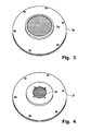
- the burner mat 3 d is by means of an annular flange-like frame part 3 e (see also Fig. 3) attached to the housing door 2 by screwing.
- annular flange-like frame parts 3 e and 3 f may preferably be cold-formed sheet-metal parts made of stainless steel or aluminum castings, the attachment of the burner mat 3 d by means of the annular flange-like frame parts, although a preferred, but just one embodiment. Other embodiments are conceivable.
- burner mats are deviating from the circular shape Configuration, e.g. polygonal burner mats, depending on Housing concept of the hot water device, conceivable.
- the manufacturing cost of the water heater with the Flat burner assembly according to the invention are compared to the known hot water device relatively low, in particular due to the lower logistics and assembly costs.
- the door / burner unit manufacturing is now a single product for installation in a water heater with heat exchanger. If one uses a burner mat with high efficiency, as it is eg under the brand "CERAMAT" ® commercially used, the necessary fuel surface can be kept relatively small.
- An effective focal area of 78.5 cm 2 allows a power input of> 30 kw.
- the degree of modulation is> 1: 8.
Landscapes
- Engineering & Computer Science (AREA)
- Chemical & Material Sciences (AREA)
- Combustion & Propulsion (AREA)
- Mechanical Engineering (AREA)
- General Engineering & Computer Science (AREA)
- Physics & Mathematics (AREA)
- Thermal Sciences (AREA)
- Gas Burners (AREA)
- Housings, Intake/Discharge, And Installation Of Fluid Heaters (AREA)
Abstract
Description
- Fig. 1
- in einer schematischen Schnittdarstellung ein konventionelles Heißwassergerät mit einem in der Tür des Geräte-Gehäuses befestigten, erfindungsgemäß ausgebildeten flachen Gasbrenner,
- Fig. 2
- in einer Schnittdarstellung den Aufbau des erfindungsgemäß ausgebildeten Flachbrenners,
- Fig. 3
- eine Ansicht der Brennerseite des erfindungsgemäßen Gas-Flachbrenners, und
- Fig. 4
- eine Ansicht der Gaszufuhrseite des erfindungsgemäßen Gas-Flachbrenners.
Die ringflanschartigen Rahmenteile 3 e bzw. 3 f können vorzugsweise kaltgeformte Blechteile aus rostfreiem Stahl oder Aluminiumgussteile sein, wobei die Befestigung der Brennermatte 3 d mittels der ringflanschartigen Rahmenteile zwar ein bevorzugtes, aber eben nur ein Ausführungsbeispiel ist. Andere Ausführungsformen sind denkbar.
Claims (10)
- Heißwassergerät mit einem Gehäuse (1), das einen Heizraum (6) umschließt, in welchem ein Wärmetauscher (4), der vom zu erwärmenden Wasser durchflossen wird, angeordnet ist, und das eine Tür (2) aufweist, in welcher ein Gasbrenner (3) in Verbindung mit einer Einrichtung (3 a, 9) zum Zuführen eines Gas/Luftgemisches (10) angebracht ist, dadurch gekennzeichnet, dass der Gasbrenner (3) eine flache Brennermatte (3 d) aufweist, die beidseitig mittels metallischer Rahmenteile (3 e, 3 f) in einer Öffnung der Tür (2) unter Bildung einer vormontierten Baueinheit angebracht ist.
- Heißwassergerät nach Anspruch 1, dadurch gekennzeichnet, dass der Gasbrenner zufuhrseitig im zugeordneten Rahmenteil (3 f) eine Brennerkammer (3 a) aufweist, die an die Einrichtung (3 a, 9) zum Zuführen des Gas/Luftgemisches (10) angeschlossen ist.
- Heißwassergerät nach Anspruch 2, dadurch gekennzeichnet, dass in der Brennerkammer (3 a) eine der Brennermatte (3 d) vorgeschaltete Verteilerplatte (3 c ) angebracht ist.
- Heißwassergerät nach Anspruch 3, dadurch gekennzeichnet, daß die Verteilerplatte (3 c) als Lochplatte ausgebildet ist.
- Heißwassergerät nach einem der Ansprüche 1 bis 4, dadurch gekennzeichnet, dass die Brennermatte (3 d) aus einem Vlies von keramischen Fasern besteht.
- Heißwassergerät nach Anspruch 5, dadurch gekennzeichnet, dass die keramischen Fasern durch Silizium-Karbid-Fasern gebildet sind.
- Heißwassergerät nach Anspruch 5 und 6, dadurch gekennzeichnet, dass die Brennermatte (3 d) durch eine solche gebildet ist, die unter der Marke CERAMAT® auf dem Markt ist.
- Heißwassergerät nach einem der Ansprüche 1 bis 7, dadurch gekennzeichnet, dass die flache Brennermatte kreisförmig ist und die metallischen Rahmenteile (3 e, 3 f) ringflanschartig ausgebildet sind.
- Heißwassergerät nach Anspruch 8, dadurch gekennzeichnet, dass auf der dem Heizraum (6) zugewandten Seite ein die Öffnung in der Tür (2) kreisringförmig umschließender Wärmeisolator (11) aufgebracht ist.
- Heißwassergerät nach einem der Ansprüche 1 bis 9, dadurch gekennzeichnet, dass die metallischen Rahmenteile (3 e, 3 f) durch kaltgeformte Blechteile aus rostfreiem Stahl oder durch Aluminiumgussteile gebildet sind.
Applications Claiming Priority (2)
| Application Number | Priority Date | Filing Date | Title |
|---|---|---|---|
| DE20314241U DE20314241U1 (de) | 2003-09-13 | 2003-09-13 | Heißwassergerät mit Gasbrenner |
| DE20314241U | 2003-09-13 |
Publications (1)
| Publication Number | Publication Date |
|---|---|
| EP1517101A1 true EP1517101A1 (de) | 2005-03-23 |
Family
ID=29796819
Family Applications (1)
| Application Number | Title | Priority Date | Filing Date |
|---|---|---|---|
| EP04021423A Withdrawn EP1517101A1 (de) | 2003-09-13 | 2004-09-09 | Heisswassergerät mit Gasbrenner |
Country Status (2)
| Country | Link |
|---|---|
| EP (1) | EP1517101A1 (de) |
| DE (1) | DE20314241U1 (de) |
Families Citing this family (1)
| Publication number | Priority date | Publication date | Assignee | Title |
|---|---|---|---|---|
| GB2403792A (en) * | 2003-07-08 | 2005-01-12 | Aeromatix Ltd | Gas burner for use with a cylindrical heat exchanger |
Citations (8)
| Publication number | Priority date | Publication date | Assignee | Title |
|---|---|---|---|---|
| US2987118A (en) * | 1958-03-06 | 1961-06-06 | Whirlpool Co | Gas burner |
| GB965252A (en) * | 1960-02-12 | 1964-07-29 | Stookunie Delft Nv | Improvements in or relating to oil-fired hot water boiler units |
| US3407024A (en) * | 1966-12-23 | 1968-10-22 | Eclipse Fuel Eng Co | Gas burner |
| EP0498748A1 (de) * | 1991-02-07 | 1992-08-12 | De Dietrich Thermique | Gasbeheizter gusseisener Gliederheizkessel mit totaler Vormischung |
| US5471956A (en) * | 1993-06-29 | 1995-12-05 | Miura Co., Ltd. | Heat-insulating structure for combustion equipment |
| WO2003025460A1 (en) * | 2001-09-19 | 2003-03-27 | Solebury Technical, Inc. | An improved radiator element |
| DE10148914A1 (de) * | 2001-10-04 | 2003-04-24 | Heatec Thermotechnik Gmbh | Heizeinrichtung |
| WO2003062705A1 (fr) * | 2002-01-22 | 2003-07-31 | Societe D'etude Et De Realisation Mecaniques Engeneering En Technologies Avancees | Bruleur a gaz, a face de combustion bipartite et chaudiere equipee d'un tel bruleur |
-
2003
- 2003-09-13 DE DE20314241U patent/DE20314241U1/de not_active Expired - Lifetime
-
2004
- 2004-09-09 EP EP04021423A patent/EP1517101A1/de not_active Withdrawn
Patent Citations (8)
| Publication number | Priority date | Publication date | Assignee | Title |
|---|---|---|---|---|
| US2987118A (en) * | 1958-03-06 | 1961-06-06 | Whirlpool Co | Gas burner |
| GB965252A (en) * | 1960-02-12 | 1964-07-29 | Stookunie Delft Nv | Improvements in or relating to oil-fired hot water boiler units |
| US3407024A (en) * | 1966-12-23 | 1968-10-22 | Eclipse Fuel Eng Co | Gas burner |
| EP0498748A1 (de) * | 1991-02-07 | 1992-08-12 | De Dietrich Thermique | Gasbeheizter gusseisener Gliederheizkessel mit totaler Vormischung |
| US5471956A (en) * | 1993-06-29 | 1995-12-05 | Miura Co., Ltd. | Heat-insulating structure for combustion equipment |
| WO2003025460A1 (en) * | 2001-09-19 | 2003-03-27 | Solebury Technical, Inc. | An improved radiator element |
| DE10148914A1 (de) * | 2001-10-04 | 2003-04-24 | Heatec Thermotechnik Gmbh | Heizeinrichtung |
| WO2003062705A1 (fr) * | 2002-01-22 | 2003-07-31 | Societe D'etude Et De Realisation Mecaniques Engeneering En Technologies Avancees | Bruleur a gaz, a face de combustion bipartite et chaudiere equipee d'un tel bruleur |
Also Published As
| Publication number | Publication date |
|---|---|
| DE20314241U1 (de) | 2003-12-18 |
Similar Documents
| Publication | Publication Date | Title |
|---|---|---|
| DE2100344C3 (de) | Wassererhitzer und Verfahren zu seiner Herstellung | |
| DE20314241U1 (de) | Heißwassergerät mit Gasbrenner | |
| DE2337517A1 (de) | Gasbeheizter wassererhitzer | |
| DE3304868C2 (de) | Wassererhitzer | |
| DE10002943B4 (de) | Heizeinrichtung | |
| DE10251816A1 (de) | Gasbrenner | |
| AT403092B (de) | Wasserheizgerät | |
| DE102004025223A1 (de) | Gasbeheizter Warmwasserbereiter | |
| EP0249087B1 (de) | Wärmestrahler zur Grossraumbeheizung | |
| WO2002016831A1 (de) | Gasstrahlungsbrenner | |
| DE19532273A1 (de) | Monoblock-Boiler, insbesondere für Warmwasser-Reinigungsgeräte | |
| AT405572B (de) | Wärmetauscher | |
| DE10148914A1 (de) | Heizeinrichtung | |
| DE102018102967A1 (de) | Wärmezelle mit metallischem Dämmring | |
| AT411102B (de) | Brennwert-heizgerät | |
| DE102004044445B4 (de) | Gasbeheiztes Wärmegerät | |
| WO2010037657A1 (de) | Kochgerät | |
| EP1988337B1 (de) | Brennkammer mit einer vorrichtung zur vermeidung selbsterregter verbrennungsschwingungen | |
| AT120494B (de) | Gaskocher. | |
| DE202004020230U1 (de) | Wärmetauscher | |
| AT399381B (de) | Gussgliederkessel | |
| EP0833113B1 (de) | Heizkessel | |
| DE7132394U (de) | Heizung s-Kesselofen für Warmwasser-Heizungsanlagen | |
| DE328543C (de) | Heizofen fuer Einzelraeume | |
| DE202008014933U1 (de) | Druckdurchlauferhitzer für Hochdruck-Reinigungsgeräte |
Legal Events
| Date | Code | Title | Description |
|---|---|---|---|
| PUAI | Public reference made under article 153(3) epc to a published international application that has entered the european phase |
Free format text: ORIGINAL CODE: 0009012 |
|
| 17P | Request for examination filed |
Effective date: 20040909 |
|
| AK | Designated contracting states |
Kind code of ref document: A1 Designated state(s): AT BE BG CH CY CZ DE DK EE ES FI FR GB GR HU IE IT LI LU MC NL PL PT RO SE SI SK TR |
|
| AX | Request for extension of the european patent |
Extension state: AL HR LT LV MK |
|
| AKX | Designation fees paid |
Designated state(s): DE FR GB IT NL |
|
| R17C | First examination report despatched (corrected) |
Effective date: 20070208 |
|
| RAP1 | Party data changed (applicant data changed or rights of an application transferred) |
Owner name: CERAMAT, S. COOP |
|
| RAP1 | Party data changed (applicant data changed or rights of an application transferred) |
Owner name: ORKLI, S. COOP. |
|
| STAA | Information on the status of an ep patent application or granted ep patent |
Free format text: STATUS: THE APPLICATION IS DEEMED TO BE WITHDRAWN |
|
| 18D | Application deemed to be withdrawn |
Effective date: 20150529 |