EP1517068A2 - Dispositif actionneur pour bôite de vitesses d'automobile - Google Patents
Dispositif actionneur pour bôite de vitesses d'automobile Download PDFInfo
- Publication number
- EP1517068A2 EP1517068A2 EP04021170A EP04021170A EP1517068A2 EP 1517068 A2 EP1517068 A2 EP 1517068A2 EP 04021170 A EP04021170 A EP 04021170A EP 04021170 A EP04021170 A EP 04021170A EP 1517068 A2 EP1517068 A2 EP 1517068A2
- Authority
- EP
- European Patent Office
- Prior art keywords
- motor vehicle
- housing
- vehicle transmission
- adjusting device
- nut
- Prior art date
- Legal status (The legal status is an assumption and is not a legal conclusion. Google has not performed a legal analysis and makes no representation as to the accuracy of the status listed.)
- Withdrawn
Links
Images

Classifications
-
- F—MECHANICAL ENGINEERING; LIGHTING; HEATING; WEAPONS; BLASTING
- F16—ENGINEERING ELEMENTS AND UNITS; GENERAL MEASURES FOR PRODUCING AND MAINTAINING EFFECTIVE FUNCTIONING OF MACHINES OR INSTALLATIONS; THERMAL INSULATION IN GENERAL
- F16H—GEARING
- F16H61/00—Control functions within control units of change-speed- or reversing-gearings for conveying rotary motion ; Control of exclusively fluid gearing, friction gearing, gearings with endless flexible members or other particular types of gearing
- F16H61/26—Generation or transmission of movements for final actuating mechanisms
- F16H61/28—Generation or transmission of movements for final actuating mechanisms with at least one movement of the final actuating mechanism being caused by a non-mechanical force, e.g. power-assisted
- F16H61/32—Electric motors actuators or related electrical control means therefor
-
- F—MECHANICAL ENGINEERING; LIGHTING; HEATING; WEAPONS; BLASTING
- F16—ENGINEERING ELEMENTS AND UNITS; GENERAL MEASURES FOR PRODUCING AND MAINTAINING EFFECTIVE FUNCTIONING OF MACHINES OR INSTALLATIONS; THERMAL INSULATION IN GENERAL
- F16H—GEARING
- F16H61/00—Control functions within control units of change-speed- or reversing-gearings for conveying rotary motion ; Control of exclusively fluid gearing, friction gearing, gearings with endless flexible members or other particular types of gearing
- F16H61/26—Generation or transmission of movements for final actuating mechanisms
- F16H61/28—Generation or transmission of movements for final actuating mechanisms with at least one movement of the final actuating mechanism being caused by a non-mechanical force, e.g. power-assisted
-
- F—MECHANICAL ENGINEERING; LIGHTING; HEATING; WEAPONS; BLASTING
- F16—ENGINEERING ELEMENTS AND UNITS; GENERAL MEASURES FOR PRODUCING AND MAINTAINING EFFECTIVE FUNCTIONING OF MACHINES OR INSTALLATIONS; THERMAL INSULATION IN GENERAL
- F16H—GEARING
- F16H63/00—Control outputs from the control unit to change-speed- or reversing-gearings for conveying rotary motion or to other devices than the final output mechanism
- F16H63/02—Final output mechanisms therefor; Actuating means for the final output mechanisms
- F16H63/30—Constructional features of the final output mechanisms
- F16H63/304—Constructional features of the final output mechanisms the final output mechanisms comprising elements moved by electrical or magnetic force
- F16H2063/3063—Constructional features of the final output mechanisms the final output mechanisms comprising elements moved by electrical or magnetic force using screw devices
-
- F—MECHANICAL ENGINEERING; LIGHTING; HEATING; WEAPONS; BLASTING
- F16—ENGINEERING ELEMENTS AND UNITS; GENERAL MEASURES FOR PRODUCING AND MAINTAINING EFFECTIVE FUNCTIONING OF MACHINES OR INSTALLATIONS; THERMAL INSULATION IN GENERAL
- F16H—GEARING
- F16H63/00—Control outputs from the control unit to change-speed- or reversing-gearings for conveying rotary motion or to other devices than the final output mechanism
- F16H63/02—Final output mechanisms therefor; Actuating means for the final output mechanisms
- F16H63/30—Constructional features of the final output mechanisms
- F16H2063/3089—Spring assisted shift, e.g. springs for accumulating energy of shift movement and release it when clutch teeth are aligned
-
- F—MECHANICAL ENGINEERING; LIGHTING; HEATING; WEAPONS; BLASTING
- F16—ENGINEERING ELEMENTS AND UNITS; GENERAL MEASURES FOR PRODUCING AND MAINTAINING EFFECTIVE FUNCTIONING OF MACHINES OR INSTALLATIONS; THERMAL INSULATION IN GENERAL
- F16H—GEARING
- F16H25/00—Gearings comprising primarily only cams, cam-followers and screw-and-nut mechanisms
- F16H25/18—Gearings comprising primarily only cams, cam-followers and screw-and-nut mechanisms for conveying or interconverting oscillating or reciprocating motions
- F16H25/20—Screw mechanisms
- F16H25/2021—Screw mechanisms with means for avoiding overloading
-
- F—MECHANICAL ENGINEERING; LIGHTING; HEATING; WEAPONS; BLASTING
- F16—ENGINEERING ELEMENTS AND UNITS; GENERAL MEASURES FOR PRODUCING AND MAINTAINING EFFECTIVE FUNCTIONING OF MACHINES OR INSTALLATIONS; THERMAL INSULATION IN GENERAL
- F16H—GEARING
- F16H63/00—Control outputs from the control unit to change-speed- or reversing-gearings for conveying rotary motion or to other devices than the final output mechanism
- F16H63/02—Final output mechanisms therefor; Actuating means for the final output mechanisms
- F16H63/30—Constructional features of the final output mechanisms
- F16H63/304—Constructional features of the final output mechanisms the final output mechanisms comprising elements moved by electrical or magnetic force
Definitions
- the invention relates to a motor vehicle transmission adjusting device for generating Actuating movements for gear change operations of a motor vehicle transmission, which elastic Has elements, a use of such, as well as a motor vehicle transmission device with such a motor vehicle transmission actuator.
- Such motor vehicle actuating devices with an elastic element can also be used as such referred to as switching elasticity units (Shift Elasticity Unit).
- US 6,003,649 shows various representations of designs in which a Elasticity or an elastic element is provided. Further, in the cited documents different force-displacement curves are shown, which show the behavior when using the Represent respective elastic elements (US 6,003,649, US 6,220,109). US 6,003,649 and US 6,220,109 mention various types and materials of such elastic elements. In particular, there are also called different types of springs that used can be to cause the elasticity.
- the Suggestions include how such actuators or actuators in designed and arranged a motor vehicle transmission or an automated transmission can be.
- the invention has for its object to provide a motor vehicle transmission actuator for Generating adjusting movements for gear change operations of a motor vehicle transmission to create, which is reliable and inexpensive to produce.
- the invention is based on the object, a To provide motor vehicle transmission actuating device, which is suitable for generating actuating operations in the context of gear changes in parallel transmissions suitable.
- a motor vehicle transmission adjusting device for Generating adjusting movements which a movably arranged threaded spindle having, with its thread in a thread of a movably arranged nut engages, so that this threaded spindle load this nut or impelling driving can, and which is also a movable and relative to the mother arranged relatively movable Housing, as well as two elastic elements, wherein a first of these elastic Elements arranged between the nut and the housing so that the nut is the housing load in a first orientation of its axial direction via this first elastic element or drivingly charged, and wherein the second of these elastic elements so between the mother and the housing is arranged, that the mother over the housing over this second elastic element in a second, the first opposite, orientation burden their axial direction or can impose a driving burden.
- the threaded spindle is rotatably arranged or mounted or rotatably movable and axially resistant.
- the first and second elastic element in each case so between the nut and the housing is arranged, that the mother the first and second elastic Element, depending on the direction of movement of the mother, immediately charged when the mother is moved.
- a certain game or a kind Leerhub is provided, which causes the mother is first moved before they respective elastic element loaded and over the load of this elastic element in turn, the housing is loaded in one or the other axial direction.
- the housing in two opposite housing walls or Housing wall sections each have an opening, in particular through opening, on, wherein the threaded spindle extends through these two through holes.
- Such through holes can be arranged in a housing wall or housing shell be. It is further preferred that such passage openings in a housing cover or nozzles or plugs are arranged, which are inserted into the (remaining) housing or screwed in.
- Such a lid may in particular also be permitted as a nozzle or plug.
- a lid or housing cover is a nozzle or grafting, so that the term (housing) cover is to be understood broadly, and in particular a nozzle or grafting with covers.
- the addressed lid may in particular be a detachable lid.
- the solubility can in particular be such that the lid close an opening in the housing or partially can close or release.
- such a cover on its outer circumferential surface Thread on, with which it is screwed into an opening in the housing, which is also a thread having. It is preferably provided that the spindle is in two places the housing extends out, in each case a removable or detachable at these locations Cover is provided, which is provided with a passage opening, and in the housing screwed, or otherwise releasably secured there.
- the threaded spindle at two points out of the housing extends, provided at any of these locations a housing cover of the type mentioned is.
- the housing is secured by means of a rotation against rotation.
- a rotation can, for example, have a linear guide.
- a linear guide arranged so that it is a substantially parallel to the spindle arranged guide rod, which is the spindle is spaced and extends through the housing.
- the guide rod extends for example so through the housing or a housing opening that they are their radial directions or in the radial direction - optionally with little play - held on the housing becomes.
- the threaded spindle is supported - possibly via the Nut - so against the housing from that the housing with respect to the radial direction or the Radial directions of the threaded spindle - possibly with little play - on this is held.
- a separate passage opening or a plurality of separate passage openings in Housing are provided.
- the anti-rotation device secures the housing against rotation about the spindle axis or an axis parallel thereto.
- the housing is against rotation with respect to the nut secured.
- a rotation by means of which the nut relative to the housing secured against rotation, for example, be such that this rotation a longitudinal or axial displacement of mother to housing allows, however, a Twisting essentially prevented.
- a longitudinal groove may be provided on the housing be, in which engages a arranged on the nut key, or vice versa.
- the nut is trapped in the housing.
- the mother can for example, be caught axially. It can also be caught radially. Especially preferred is the combination of these two designs.
- the housing is a housing of the mother or a nut enclosing or catching housing.
- a chamber is provided in the housing, in which the two elastic elements and the nut are arranged. Particularly preferred is provided that through openings of the housing open into this chamber, through which the Threaded spindle extends. It is further preferred that a guide rod an anti-rotation for the housing extends through the housing, outside a chamber of the kind addressed.
- the housing is coupled to at least one shift shaft.
- This can be a direct or indirect coupling, so be designed so that the housing directly, for example via a toothing or the like, in a switching shaft or a toothing arranged there engages, or so that elements are interposed.
- the housing load such a switching shaft drivingly can.
- the housing is coupled to at least one shift finger is, where also the coupling can be direct or indirect.
- the housing can drive the shift finger driving.
- the housing is preferred arranged relatively movable relative to the shift shaft and / or the shift finger. Prefers is further that the housing fixedly connected to the shift shaft and / or the shift finger is.
- Such a shift finger is in a particularly preferred design of a shift shaft arranged the said type.
- the shift finger rotatably connected to the shift shaft. He can axiaffest example, with the shift shaft be coupled, or axially movable to be arranged on this.
- the housing is preferably provided with a toothing, and was particularly preferred with a toothing arranged on the outside of the housing.
- a gearing may for example be a rack or a rack-like element.
- a gear segment or such Gear arranged on a shift shaft or on a shift finger.
- the first elastic element is in a preferred design a spring. It is further preferred that the second elastic element is a spring. It can be provided that such Spring is arranged in each case so that acts as a compression spring.
- the first elastic element is a plate spring. It is further preferred that the second elastic element is a plate spring. It but can also be provided that elastic elements of other types are provided.
- the elastic elements act in a particularly preferred design in operation as energy storage or as energy storage, the drive energy or a part of the drive energy stores.
- the housing has a Gearing or rack carries, and this rack or these teeth in a Gear or a gear segment engages which on the shift finger and / or on the Shift rod is arranged so that the shift finger and / or the shift rod in operation can be charged.
- at axial displacement of the housing such a gear or gear segment is moved pivoting or rotating.
- the shift finger a Can burden shift rail or loaded driving in operation or with appropriate relative position driving burdened.
- the shift finger in a Swivel movement during operation executes and about this pivoting movement such Shift rail translationally move in a first direction or in a second direction can or, respectively, load accordingly, to cause such a movement.
- the first and / or the second elastic element is biased.
- an adjusting device is provided, by means of which such Bias of the first and / or the second elastic element is adjustable. It can be provided that an adjustment is designed so that from the outside of the housing this bias is adjustable.
- a housing cover of the type mentioned, that is, such a lid which is screwed in the housing is, and through which optionally extends the threaded spindle.
- such an adjustment is designed so that at the same time the first and the second elastic element are adjusted by them can, or the bias of these elements are set simultaneously or simultaneously can.
- At least one first stop means is provided, through which the Deformation or spring travel of the first elastic element or the first elastic Spring is limited. It can also be provided, for example, that such a first Slip means is adjustable so that the stop position can be adjusted.
- the first Lifting means is preferably such that a stop position is reached before the first elastic element has deformed a maximum or is compressed to the maximum, or - in particular when designed as a spring first elastic element - the spring their maximum travel or has reached the minimum spring length. For example, this may be the case Spring is a compression spring and strike the stop means or in a stop position go before this spring is completely compressed.
- a second stop means may be provided which in the same or corresponding manner designed and / or arranged as the first elastic Element, and provided for the second elastic member and the second spring is.
- the nut has a first recess, in which the first elastic element is absorbed. It may also be provided that the mother is supplementary or alternatively, a second recess, in which the second elastic element is recorded. Particularly preferred is at the two axial ends of the nut each provided with a recess, one of which is a first recess, which is the first elastic Receives element or the first spring, and the other is a second recess, the receives the second elastic element or the second spring.
- Design affects a (respective) surface area of the mother, to such a recess adjacent, in cooperation with a surface portion of the housing, namely in particular a surface portion of the housing located on the inside of the housing Housing, as the first and second stop means.
- the first and / or the second stop means is preferably a mechanical one Slings.
- the nut is in its radially outer region on the housing guided, in particular axially guided.
- the mother preferably essentially contacts the housing with its radially outer region, where appropriate, low clearance given is.
- the threaded spindle is in a particularly preferred design axially fixed about its longitudinal axis rotatably mounted.
- a drive device such as an electric motor, for Driving the threaded spindle provided.
- a drive device can directly or be coupled via further intermediate elements with the threaded spindle.
- Prefers can the direction of rotation of the motor output shaft designed as an electric motor drive device be switched.
- an electronic control device is provided, by means of which the Electric motor can be controlled.
- Such an electronic control unit can, for example be an electronic transmission control unit.
- the inventive design of an adjusting device which is also known as switching or Actuating elasticity assembly or switching elasticity unit or construction, preferably has the characteristics and advantages disclosed in U.S. Patents 6,003,395; 6,220.109 B1 and 6,003,649 in terms of the use of elastic elements are called.
- the inventive design an actuator allows by their design and / or the arrangement of their Components that they can also be used for transmissions in which the known designs - For reasons of space or the like - are less suitable. This means, however not that the inventive design have these advantages in each embodiment got to; Rather, the possibility is achieved by the invention, such advantageous To realize designs.
- the adjusting device according to the invention or the inventive Heidelbergelastizticianskonstrutation is preferably so, the elastic elements at each of the two ends of a threaded provided mother, the elasticity to an adjacent mother housing can be able to absorb or guarantee.
- a motor vehicle transmission device with a Actuating device for controlling gear change operations of the motor vehicle transmission device proposed, wherein by means of this actuator a respective Gear can be selected in a respective gear of the motor vehicle transmission device be switched and the motor vehicle transmission device are switched to neutral can, this actuator is a motor vehicle transmission adjusting device according to the invention having.
- This motor vehicle transmission device is preferably operated as an automated Motor vehicle transmission device designed. It can be automated, for example Be switched manual transmission.
- this motor vehicle transmission device as Parallel gearbox (PSG) designed.
- PSG Parallel gearbox
- the motor vehicle transmission device an inline parallel gearbox.
- USB uninterruptible transmission
- a motor vehicle transmission adjusting device The inventive type and / or an actuating device with a a motor vehicle transmission adjusting device of the type according to the invention for actuating a Motor vehicle transmission device to use. It is particularly preferred that a Such adjusting device or actuating device for actuating a motor vehicle transmission device used, which is a parallel shift transmission (PSG).
- PSG parallel shift transmission
- Preferred according to the invention a use of the adjusting device according to the invention in an actuating device for an inline parallel shift transmission of a motor vehicle, which in particular Preferred design is such as in the British patent application 0223531.5 is described.
- a Motor vehicle transmission adjusting device for shifting in gears of the motor vehicle transmission device is used.
- the switching into the gears carried out by means of an adjusting device according to the invention becomes.
- switching in neutral or the taking out of the gears carried out by means of an adjusting device according to the invention becomes.
- an adjusting device according to the invention can also be used to do so effecting or controlling said "dialing" in a motor vehicle transmission device. It can also be provided that an adjusting device according to the invention both for "Select”, as well as for “switching” is used in a motor vehicle transmission.
- the adjusting device according to the invention is preferred for Gereteebetutzs- or Gear shift mechanism used in which a threaded spindle for actuating or Switching is used.
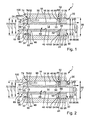
- Fig. 1 is a sectional view of an exemplary adjusting device according to the invention in a first position in a schematic representation
- FIG. 2 shows the design according to FIG. 1 in a second position
- Fig. 3 shows an exemplary adjusting device according to the invention, for example, the Adjusting device according to Figures 1 and 2 may be, in a schematic exploded view.
- Fig. 4 is an exemplary adjusting device according to the invention, for example, the Adjusting device according to FIGS. 1 and 2 and / or Fig. 3 may be, in a schematic three-dimensional View.
- Fig. 1 shows an exemplary design of an adjusting device according to the invention in cut view in a first position.
- Motor vehicle transmission adjusting device 1 has a first energy storage device 10 or a first elastic element 10 and a second energy storage device 12 and a second elastic element 12. Further, the motor vehicle transmission adjusting device 1 a threaded spindle 14, a nut 16 and a housing 18.
- the housing 18 has a third housing opening 20, on or in which a lid or a nozzle or a plug 22 is arranged, which for simplicity in the following as a lid 22 is designated, and in particular can be designed as a neck or plug.
- This cover 22 is adjustable. In the embodiment of FIG. 1, this cover 22 is detachable and detachable so that it can be completely removed from the rest of the housing 18. It can also be provided that this cover 22 in its dissolved or open position is still held on the housing 18.
- the lid 22 carries a thread 24 which is arranged with a housing 18 on Thread 26 is screwed.
- a thread 24 which is arranged with a housing 18 on Thread 26 is screwed.
- an adjustment device for adjusting the bias of the elastic members 10, 12 created.
- the lid 22 can serve for assembly or disassembly purposes.
- an adjustability of the bias of the elastic Elements 10, 12 can be achieved in other ways.
- can be provided be used to adjust the preload spacers that are in their Number can be varied to achieve different biases.
- Such Spacers may, for example, in the region of the respective elastic element 10, 12th be positioned.
- assembly or disassembly can - alternatively or additionally - be provided other configurations, such as a housing pitch or like.
- the thread 26 arranged on the housing 18 is in the third housing opening 20 provided internal thread.
- the worn by the cover 22 thread 24 is designed in FIG. 1 as an external thread and can be screwed to the internal thread 26 become.
- the recorded in the third housing opening 20 cover or nozzle 22 forms a Housing wall or a second housing wall portion 28 of the housing 18.
- the lid 22 is provided with an opening 30 which serves as a through hole or passage opening 30 is designed, and forms a second housing opening 30.
- This second housing opening 30th is in the embodiment of FIG. 1 substantially concentric with the thread 24 of the lid or socket 22, so that the second housing opening 30 in different Positions or screw positions of the lid 22 retains its radial position.
- a first housing opening 34 is provided, which serves as a passage opening or Through hole 34 is designed.
- first housing opening 34 is concentric with the opposite housing wall or in the lid 22 provided second housing opening 30 is arranged.
- the second 30 and the first housing opening 34 are each designed cylindrical and have the same inner diameter. But it can Also be provided different inner diameter.
- these openings 30, 34 also have other opening cross-sections and / or be designed stepped.
- a lid or a nozzle or a plug is provided, in which the first housing opening 34 is arranged.
- This one may be in terms of its design and arrangement, for example, as described with respect to the lid 22. It can therefore be provided that in the opposite housing wall sections 28, 32 each have a lid is provided which is provided with an opening and optionally is screwed in the housing 18.
- a first chamber 36 is arranged or is formed.
- This chamber 36 may be, for example, a substantially cylindrical interior.
- the Housing openings 30, 34 open into this chamber 36.
- the chamber 36 is in the design of FIG. 1 - apart from the housing openings 30, 34 - substantially closed.
- the housing 18 can also be designed differently be. It can be provided, for example, that the housing in the region of the chamber Has 36 axial limits, which are connected by axially extending webs.
- the threaded spindle 14 has a thread 38 which is designed as an external thread.
- the nut 16 has a thread 40 which is designed as an internal thread.
- the mother 16 For example, it may be designed to have a cylindrical portion 42 as well one or more radially projecting from this cylindrical portion 42 annular flanges 44, 46.
- the nut 16 may be configured to be cylindrical and having a substantially constant outer diameter, or otherwise.
- annular flanges 44, 46 are provided, which in Substantially disposed at the two axial ends 48, 50 of the cylindrical portion 42 are.
- These annular flanges 44, 46 have axial projections 52, 54.
- These axial projections 52, 54 extend from the respective annular flanges 44, 46 axially in the respective other annular flange 44, 46 facing away.
- the axial projections 52, 54 are radial outside the respective annular flange 44, 46 arranged.
- the axial projections 52, 54 can for example, be cylindrically shaped.
- the first axial projection 52 which is arranged on the first annular flange 44, adjoins a first recess 56 of the nut 16.
- the second axial projection 54, on the second annular flange 46 is adjacent to a second recess 58 of the nut 16.
- the depressions 54, 58 are cylindrical and over the provided with the thread 40 passage opening 59 of the mother 16 connected.
- the nut 16 may for example - in particular apart from the thread - rotationally symmetrical be designed.
- the mother can also be designed in a different form. It can also be provided that it has elements or grooves or the like, which, for example Part of an anti-rotation, which the housing 18 opposite the mother 16 secures against twisting.
- the mother 16 may, for example, apart of elements or grooves that are part of a rotation, and apart from Be designed thread rotationally symmetrical.
- the first elastic element 10 and the second elastic element 12 may be made of metal or plastic or other elastic material.
- the first energy storage or the first elastic element 10 and the second energy store or the second elastic Element 12 is shown in FIG. 1 as a spring or plate spring 60, 62 permitted. It can also be provided that energy storage or elastic elements 10, 12 are provided are, which are not disc springs, such as plastic blocks, coil springs or the like.
- the first plate spring 60 and the second plate spring 62 are each designed annular, so that they each have a passage opening 64 and 66, respectively.
- the threaded spindle 14 is rotatably mounted. For this purpose, suitable storage means be provided.
- the threaded spindle 14 is also mounted axially fixed. She can look after her Turn longitudinal axis or axis of rotation or be rotated, either in one or the opposite direction of rotation.
- the threaded spindle 14 can with the Output shaft of an electric motor be coupled to the threaded spindle 14 accordingly driving or driving can drive.
- an electronic control unit may be provided be that drives the electric motor.
- the threaded spindle 14 extends through the second through-opening 30 of the housing 18 and the lid 22 and through the first passage opening 34 in the lid 22nd opposite housing wall or housing wall portion 32 of the housing 18 is provided is.
- the threaded spindle 14 engages with its thread 38 in the thread 40 of the nut 16, so the threaded spindle 14 can drive the nut 16 in a driving manner.
- the nut 16 is movably arranged and can travel along the threaded spindle 14 is So relative to the threaded spindle 14 arranged relatively movable.
- the first elastic element 10 which in the Design as shown in FIG. 1 is designed as a plate spring 60, arranged so that the nut 16th the housing 18 in a first orientation of the axial direction, by the arrow 68 schematically is indicated, can load on the first elastic element 10 drivingly.
- first elastic element 10 or the Belleville spring 60 axially between a region of the nut 16, the - as shown in Fig. 1 - first annular flange 44 of the nut 16 may be or an end face of the nut 16, and a portion of the housing 18, which - as shown in Fig. 1 - the housing portion 32nd can be arranged.
- the first elastic element 10 or the one contacted Plate spring 60 in the unloaded rest position axially this area of this nut 16 and the first annular flange 44 of the nut 16 and this area of the housing 18 and the housing portion 32.
- the mother 16, the housing 18 is already driving over the first elastic element 10 and the plate spring 60 in the first orientation 64 of the axial direction load when the threaded spindle 14 starts from an unloaded rest position, driving the nut 16 in the direction of the arrow 68.
- the first plate spring 60 is received in the first recess 56 of the nut 16.
- the outer dimension or the outer diameter 70 of the first disc spring 60 is smaller than the outer diameter or the outer dimension 72 of the nut 16 and the first annular flange 44 of the nut 16.
- the first plate spring 60 is from the first annular flange Held 44 and supports with its radially outer region radially inward the first axial projection 52 from. It can also be secured there, for example clamped, be.
- first stop means 74 The deformation of the first elastic member 10 and the spring travel of the first Spring or first plate spring 60 is limited by a first stop means 74.
- the first spring or first plate spring 60 is arranged so that they are in the Operation is loaded on pressure or can be compressed or acts as a compression spring. there is the way or the amount to or to which this spring can be compressed limited.
- first surface area 76 of the Housing 18 in cooperation with a first surface portion 78 of the nut 16 as Slings act.
- This first surface area 76 of the housing 18 is on the inside of the housing on the first housing wall or the first housing wall section 32 arranged and the first surface portion 78 of the nut 16 is an end face 80 of the first axial projection 52.
- the second elastic element 12 is designed as a plate spring 62 in the design shown in FIG. 1, arranged so that the nut 16 the housing 18 in a second, the first opposite, orientation of the axial direction, which is indicated schematically by the arrow 82, via the second elastic element 12 can tax.
- second elastic element 12 or the Belleville spring 62 axially between a region of the nut 16, the -.
- second annular flange 46 of the nut 16 may be or an end face of the nut 16, and a portion of the housing 18 which, as shown in FIG. 1, may be the lid 22, is arranged.
- the second elastic element 12 or the one contacted Plate spring 62 in the unloaded rest position axially the area of this nut 16 and the second annular flange 46 of the nut 16 and this area of the housing 18 and the lid 22.
- the nut 16, the housing 18 is already driving on the second elastic Load element 12 or plate spring 62 in the second orientation 82 of the axial direction, when the threaded spindle 14 starts from an unloaded rest position, the nut 16 in the direction of arrow 82 impelling to load.
- the second plate spring 62 is received in the second recess 58 of the nut 16.
- the outer dimension or the outer diameter 84 of the second Plate spring 62 is smaller than the outer diameter or the outer dimension 86 of the nut sixteenth or the second annular flange 46 of the nut 16.
- the second plate spring 62 is of the second axial projection 54 is held or supported with its radially outer region radially inward from the second annular flange 46. It can also be secured there, for example be clamped.
- the deformation of the second elastic member 12 and the spring travel of the second spring or second plate spring 62 is limited by a second stop means 88 is.
- the second spring or second disk spring 62 is arranged in such a way that that it is subjected to pressure during operation or can be compressed or as Compression spring acts. In this case, the way or the measure is compressed or to which this spring can be limited.
- a second surface area 90 of the Housing 18 in cooperation with a second surface portion 92 of the nut 16th act as a stop means.
- This second surface area 90 of the housing 18 is on the Housing inside of the second housing wall and the second housing wall portion 28th and the lid 22 and the second surface portion 92 of the nut 16 is a End face 94 of the second axial projection 54th
- the housing 18 is arranged relative to the nut 16 movable relative. Furthermore, that is Housing 18 movably arranged.
- the nut 16 is guided on the housing 18. This is so that the first 44 as well as the second Ring flange 46 of the nut 16 and the first axial projection 52 and the second axial projection 54 are supported radially on the outside of the housing. It can also be provided that the axial clearance between the annular flanges 44, 46 is filled with material or the Nut 16 has a substantially constant outer diameter, and the mother 16th is supported on the housing 18 with this radially outer region. It can be radial There may also be some play between the nut 16 and the housing 18.
- the elastic elements 10 and 12 and the disc springs 60, 62 and the nut 16 are housed in the housing 18 and in the chamber 36 of the housing 18.
- the mother 16 is in Mother housing or housing 18 caught, in particular axially.
- the mother 16 is in Substantially disposed axially between the disc springs 60, 62.
- the elastic elements 10 and 12 and the disc springs 60, 62 are biased. These Bias is adjustable in the design of FIG. 1.
- By further screwing the cover 22 in the housing can be the bias of the elastic elements 10 and 12 or disc springs 60, 62 increase.
- the disc springs 60, 62 biased to a predetermined extent by the extent of the depth in which the lid or the plug 22 is inserted into the housing 18 or is screwed in.
- no bias voltage is generated or the elastic elements 10 and 12 or the disc springs 60, 62 optionally in the unloaded Hibernate with game are arranged. This can also be preferred by means of reach the lid 22.
- the stop positions the stop means 74 and / or 88 are adjustable.
- an adjustment be provided.
- This can for example also be such that the stop position is adjustable from the outside.
- a screw may be provided in each case from the outside in the first and second housing wall and the first and second housing wall portion 32, 28 and cover 22 is screwed in one place, on the end face 80 and 94 of the first and second axial projection 52, 54 is moved, so that this end face 80 or 94 or this projection instead of the inner surface of the first or the second housing wall or of the first or second housing wall section 32, 28 Cover 22 abuts against the screw shaft end of this screw, whose position can be changed by screwing.
- the axial Projections 52, 54 each in a corresponding annular groove in the lid 22 and in the first or second housing wall 32, immerse 28 and in this annular groove from the outside an adjustable Screw for setting the stop position opens. It can also be provided that only the first or only the second stop means with respect to their stop position are adjustable, or both.
- the values of the preload, the compression rate or spring rate and the mechanical Stops 74, 88 can also by the choice of different or different elastic Elements 10, 12 and disc springs 60, 62 are changed.
- the nut 16 opposite the housing 18 is secured by means of a rotation against relative rotation.
- the nut 16 radially outward or on the inside of the housing be provided in the axial direction extending groove, and on the other part a key or the like, so that the nut 16 and the housing 18 in the axial direction are arranged relatively movable, and are rotatably coupled with respect to their longitudinal axis.
- actuation or switching elasticity is not in all situations or under is desired in all conditions. It may be that no elasticity or actuation or Switching elasticity is desired when low forces are used or act. Corresponding it may be undesirable for a pronounced elastic movement to take place, when large loads or forces act.
- Fig. 1 a position is shown, which is given when low forces from the nut 16 on the housing 18 are transferred.
- the springs 60, 62 are biased.
- the spring 60 transmits the load or load from the nut 16 on the housing 18 without deforming or to deform significantly.
- the extent to which deform the first elastic member 10 and the plate spring 60 can or can be compressed or compressed can, is limited. This limitation takes place via the first stop means 74.
- FIG. 2 now shows this design in a fully compressed Position or in a fully compressed state, in which the first stop means 74 are in a stop position.
- the first surface area 78 of the nut 16 contacted - in the given in Fig. 2 accordingly the first surface portion 76 of the housing 18th
- the second elastic element 12 or second plate spring lies 62 here but no longer both on the nut 16, as well as on the housing 18 and the housing cover 22 on. But it can also be provided that spring elements used be, in which a concern would be given here or that the lid 22 accordingly further screwed into the housing 18.
- the plate spring 60 is in the stop position in Essentially completely absorbed in the recess 56 of the nut 16.
- the deformation or spring travel of the first elastic element 10 or the first Disk spring 60 is, as already mentioned, limited. This limit is such that the spring 60 can not be fully compressed, or can go to block, but before is limited by means of the aforementioned stop means the spring travel.
- the complete compressed position, which was addressed above, is thus, in which in one of the both possible load directions the spring is compressed to the maximum, which does not mean that the spring itself, if used in other applications, would not work would compress further.
- FIG. 3 shows an exemplary motor vehicle transmission adjusting device according to the invention in FIG schematic exploded view. This design can be in particular as it is based 1 and 2 has been described.
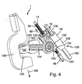
- FIG. 3 shows that the threaded spindle 14 has a connection region 120.
- This connection region 120 can be connected to a drive device become.
- a drive device is preferably an electric motor.
- the threaded spindle 14 rotatably on the connection area 120 is coupled to the motor output shaft of an electric motor. It can also be provided be that translation stages between such an engine output shaft and this Connection area 120 are provided.
- the threaded spindle 14 is the motor output shaft at the same time. It is specifically intended that a Such electric motor can drive the threaded spindle 14 in both directions of rotation, or optionally in one or the other. It can be provided, for example, that the electric motor can be switched accordingly.
- the threaded spindle 14 extends in the assembled state through the chamber 36 and by the housing 18. Parallel to the central axis 122 of the mounted threaded spindle 14 has the housing has a passage opening 124 arranged outside the chamber 36. These Through opening 124 is part of a rotation or a linear guide for the housing 18 and serves to receive a guide rod, the example in FIG. 4th is shown. Between the provided with this passage opening 124 housing portion 126 and the housing portion 128, in which the chamber 36 is arranged, is a housing portion 130 is provided, which has a toothing 132 and a rack 134.
- FIG. 4 shows an exemplary design of a transmission actuating device according to the invention or adjusting device in a three-dimensional schematic view.
- the shown in Fig. 4 Adjusting device may for example also be designed as it is based on the Fig. 1 and Figure 2 and / or as explained with reference to Figure 3.
- This gear segment 152 is rotatably connected to a switching shaft 154, which in turn rotationally fixed to a shift finger 156 is arranged.
- the toothing 150 or the gear segment 152, in which or which the toothing 132 and the rack 134 engages, is provided directly on the shift finger 156.
- the housing 18 has an anti-rotation lock 158.
- This rotation lock 158 is like this substantially preventing the housing 18 from pivoting about the longitudinal axis 122 of FIG Spindle 14, or an axis parallel thereto, can be rotated.
- This rotation lock 158 has a through opening 124, already mentioned in FIG. 3, in which a Guide rod 160 is added.
- the guide rod 160 is preferably fixedly mounted, for example, on a housing that is different from the housing 18 and against which the housing 18 is movably arranged.
- the guide rod 160 is received in the in the through hole 124 of the housing 118.
- the passage opening 124 of the housing 18 and the housing 18 is axially movable on the guide rod 160 arranged.
- the guide rod 160 may also be in the through hole 124 of the housing 118 may be arranged that this arrangement alone a rotational mobility of the housing 118 would allow for the guide rod 160, but which thereby prevents housing 18 at a second location, in particular in the area of Chamber, also held.
- the guide rod 160 is substantially parallel to the Longitudinal axis 122 of the spindle 14 is arranged.
- the gear segment 152 is designed in a substantially quarter-circle, or a quarter-circular gear segment; this part can also be called a quadrant. But it can also cover a different angle range, such as a third circle or another segment part. But it can also be a gear.
- the shift finger 156 is arranged to be within an inner profile 164 or a passage opening given in the axial direction, the side is open, a shift rail 166 is arranged.
- the Shifting rail 166 axially or in the longitudinal direction of this shift finger 156, which by the arrow 186 schematically indicated, moved or loaded.
- This can, for example, a Synchronization ring or the synchronization of a transmission loaded or operated or switched to a gear in the transmission.
- Fig. 4 in a partial schematic view in particular a Getriebebetuschists- or gear shifting device shown. From Fig. 4 shows in particular how the Housing 18, the shift finger 156 and the shift rail 166 moves. In particular, there is also shown that in the housing 18, a rack is integrated, which is a quadrant or a provided with quadrant teeth or gear segment, a shift shaft and the shift finger 156 moves or pivots.
- the shift finger 156 pushes against an inner profile of the shift rail, or is the Shift finger 156 against an inner profile of the shift rail 156 is moved or pushed, and the shift finger 156 moves this shift rail 156 linearly.
- a plurality of shift rails or the like may be arranged.
- several such Shift rails be arranged substantially parallel, in such a way that in a neutral position a respective shift rail of the shift finger axially through the corresponding openings can be moved in the shift fingers.
- By selecting the appropriate position can be “selected”, which shift rail in a subsequent switching operation by means of a to be actuated in Fig. 4 adjusting device.
- a additional adjusting device is provided which this longitudinal displacement of the shift finger 156 in the direction of the switching shaft 154 can cause.
- This second adjusting device can also be designed in a different way than the inventive design of a control device. It can also be provided that such an additional adjusting device a Electric motor has. Such additional job direction can cause the Switching shaft 154 can be moved in its axial direction. It can also be designed that is moved, that the shift finger 156 are moved axially along the switching shaft 154 can.
Applications Claiming Priority (2)
| Application Number | Priority Date | Filing Date | Title |
|---|---|---|---|
| DE10342829 | 2003-09-17 | ||
| DE10342829 | 2003-09-17 |
Publications (2)
| Publication Number | Publication Date |
|---|---|
| EP1517068A2 true EP1517068A2 (fr) | 2005-03-23 |
| EP1517068A3 EP1517068A3 (fr) | 2009-09-16 |
Family
ID=34177782
Family Applications (1)
| Application Number | Title | Priority Date | Filing Date |
|---|---|---|---|
| EP04021170A Withdrawn EP1517068A3 (fr) | 2003-09-17 | 2004-09-07 | Dispositif actionneur pour bôite de vitesses d'automobile |
Country Status (2)
| Country | Link |
|---|---|
| EP (1) | EP1517068A3 (fr) |
| DE (1) | DE102004043116A1 (fr) |
Cited By (3)
| Publication number | Priority date | Publication date | Assignee | Title |
|---|---|---|---|---|
| CN110513456A (zh) * | 2019-09-24 | 2019-11-29 | 广州铭匠智能科技有限公司 | 一种丝杆螺母机构 |
| CN110566662A (zh) * | 2018-06-06 | 2019-12-13 | 舍弗勒技术股份两合公司 | 换挡装置及电动汽车 |
| CN112987845A (zh) * | 2019-12-13 | 2021-06-18 | 欧玛里斯特有限责任两合公司 | 调节驱动器 |
Families Citing this family (3)
| Publication number | Priority date | Publication date | Assignee | Title |
|---|---|---|---|---|
| DE102008040207A1 (de) * | 2008-07-07 | 2010-01-14 | Zf Friedrichshafen Ag | Anordnung zum Wählen und Schalten von Gängen bei einem Schaltgetriebe eines Fahrzeuges |
| DE102009030010A1 (de) * | 2009-06-23 | 2010-12-30 | Magna Powertrain Ag & Co Kg | Wandlereinrichtung |
| WO2024063058A1 (fr) * | 2022-09-22 | 2024-03-28 | 株式会社デンソー | Dispositif d'embrayage |
Citations (3)
| Publication number | Priority date | Publication date | Assignee | Title |
|---|---|---|---|---|
| GB223531A (en) | 1923-10-17 | 1924-12-11 | American Gasaccumulator Co | Improvements in flashlight apparatus |
| US6003395A (en) | 1996-08-06 | 1999-12-21 | Luk Getriebe-Systeme Gmbh | Actuating apparatus for automated constituents of power trains in motor vehicles |
| US6003649A (en) | 1996-04-03 | 1999-12-21 | Luk Getreibe-Systeme Gmbh | Method and apparatus for actuating a transmission |
Family Cites Families (3)
| Publication number | Priority date | Publication date | Assignee | Title |
|---|---|---|---|---|
| US4425814A (en) * | 1981-03-23 | 1984-01-17 | Dana Corporation | Torque limiting device |
| US4440035A (en) * | 1981-05-18 | 1984-04-03 | Dana Corporation | Slip clutch speed change mechanism |
| US4793458A (en) * | 1987-11-09 | 1988-12-27 | Dana Corporation | Shift motor assembly for a two-speed axle |
-
2004
- 2004-09-07 DE DE102004043116A patent/DE102004043116A1/de not_active Withdrawn
- 2004-09-07 EP EP04021170A patent/EP1517068A3/fr not_active Withdrawn
Patent Citations (4)
| Publication number | Priority date | Publication date | Assignee | Title |
|---|---|---|---|---|
| GB223531A (en) | 1923-10-17 | 1924-12-11 | American Gasaccumulator Co | Improvements in flashlight apparatus |
| US6003649A (en) | 1996-04-03 | 1999-12-21 | Luk Getreibe-Systeme Gmbh | Method and apparatus for actuating a transmission |
| US6220109B1 (en) | 1996-04-03 | 2001-04-24 | Luk Getriebe-Systeme Gmbh | Method and apparatus for actuating a transmission |
| US6003395A (en) | 1996-08-06 | 1999-12-21 | Luk Getriebe-Systeme Gmbh | Actuating apparatus for automated constituents of power trains in motor vehicles |
Cited By (3)
| Publication number | Priority date | Publication date | Assignee | Title |
|---|---|---|---|---|
| CN110566662A (zh) * | 2018-06-06 | 2019-12-13 | 舍弗勒技术股份两合公司 | 换挡装置及电动汽车 |
| CN110513456A (zh) * | 2019-09-24 | 2019-11-29 | 广州铭匠智能科技有限公司 | 一种丝杆螺母机构 |
| CN112987845A (zh) * | 2019-12-13 | 2021-06-18 | 欧玛里斯特有限责任两合公司 | 调节驱动器 |
Also Published As
| Publication number | Publication date |
|---|---|
| DE102004043116A1 (de) | 2005-04-21 |
| EP1517068A3 (fr) | 2009-09-16 |
Similar Documents
| Publication | Publication Date | Title |
|---|---|---|
| EP2823203B1 (fr) | Unité de verrouillage, en particulier pour un frein de stationnement d'une boîte de vitesses automatique | |
| EP2098743B1 (fr) | Mécanisme de réglage destiné à l'insertion et l'extraction d'un embrayage de coupure à l'aide d'un segment de came rotatif | |
| DE102010002285A1 (de) | Schraubradgetriebe für eine Lenkung eines Kraftfahrzeugs | |
| EP3608557B1 (fr) | Vis d'entraînement à bille | |
| EP0666399B1 (fr) | Dispositif d'entraînement pour un élément d'un véhicule pouvant se déplacer entre des positions finales | |
| DE112021000017T5 (de) | Verzahnungsvorrichtung, mechanische kapsel und kipphebel | |
| EP3146166B1 (fr) | Arbre à cames | |
| DE20311032U1 (de) | Antriebsvorrichtung | |
| DE102016214774B4 (de) | Drehantriebseinrichtung mit lastabhängiger Bremse | |
| EP1517068A2 (fr) | Dispositif actionneur pour bôite de vitesses d'automobile | |
| EP1898122B1 (fr) | Dispositif de réglage destiné au réglage linéaire d'un actionneur | |
| EP1882120B1 (fr) | Dispositif de verrouillage susceptible d'etre supprime, d'un element de couplage pour une transmission | |
| EP1310702B1 (fr) | Dispositif de freinage pour entraínement rotatif | |
| DE19706214A1 (de) | Stelleinrichtung eines in zwei Bewegungsarten bewegbaren Ausgangsteils | |
| DE102020129285A1 (de) | Expansionsventil | |
| EP3741934A1 (fr) | Cylindre de fermeture | |
| DE102020124871A1 (de) | Expansionsventil | |
| DE19851466A1 (de) | Stellglied | |
| EP1426641A1 (fr) | Dispositif d'actionnement d'embrayage | |
| DE10240552A1 (de) | Kraftfahrzeug Türschloß | |
| DE102004049796B4 (de) | Linearantrieb | |
| DE10159862B4 (de) | Schaltelastizität für ein automatisiertes Schaltgetriebe | |
| DE10038524A1 (de) | Automatisches Getriebe | |
| DE102020129284A1 (de) | Expansionsventil | |
| WO2023155949A1 (fr) | Dispositif d'ajustement linéaire et unité d'ajustement |
Legal Events
| Date | Code | Title | Description |
|---|---|---|---|
| PUAI | Public reference made under article 153(3) epc to a published international application that has entered the european phase |
Free format text: ORIGINAL CODE: 0009012 |
|
| AK | Designated contracting states |
Kind code of ref document: A2 Designated state(s): AT BE BG CH CY CZ DE DK EE ES FI FR GB GR HU IE IT LI LU MC NL PL PT RO SE SI SK TR |
|
| AX | Request for extension of the european patent |
Extension state: AL HR LT LV MK |
|
| PUAL | Search report despatched |
Free format text: ORIGINAL CODE: 0009013 |
|
| AK | Designated contracting states |
Kind code of ref document: A3 Designated state(s): AT BE BG CH CY CZ DE DK EE ES FI FR GB GR HU IE IT LI LU MC NL PL PT RO SE SI SK TR |
|
| AX | Request for extension of the european patent |
Extension state: AL HR LT LV MK |
|
| RIC1 | Information provided on ipc code assigned before grant |
Ipc: F16H 61/32 20060101ALI20090807BHEP Ipc: F16H 63/30 20060101ALI20090807BHEP Ipc: F16H 61/28 20060101AFI20041208BHEP |
|
| AKX | Designation fees paid | ||
| REG | Reference to a national code |
Ref country code: DE Ref legal event code: 8566 |
|
| STAA | Information on the status of an ep patent application or granted ep patent |
Free format text: STATUS: THE APPLICATION IS DEEMED TO BE WITHDRAWN |
|
| 18D | Application deemed to be withdrawn |
Effective date: 20100317 |
|
| P01 | Opt-out of the competence of the unified patent court (upc) registered |
Effective date: 20230522 |