EP1517068A2 - Actuator for a vehicle transmission - Google Patents
Actuator for a vehicle transmission Download PDFInfo
- Publication number
- EP1517068A2 EP1517068A2 EP04021170A EP04021170A EP1517068A2 EP 1517068 A2 EP1517068 A2 EP 1517068A2 EP 04021170 A EP04021170 A EP 04021170A EP 04021170 A EP04021170 A EP 04021170A EP 1517068 A2 EP1517068 A2 EP 1517068A2
- Authority
- EP
- European Patent Office
- Prior art keywords
- motor vehicle
- housing
- vehicle transmission
- adjusting device
- nut
- Prior art date
- Legal status (The legal status is an assumption and is not a legal conclusion. Google has not performed a legal analysis and makes no representation as to the accuracy of the status listed.)
- Withdrawn
Links
Images

Classifications
-
- F—MECHANICAL ENGINEERING; LIGHTING; HEATING; WEAPONS; BLASTING
- F16—ENGINEERING ELEMENTS AND UNITS; GENERAL MEASURES FOR PRODUCING AND MAINTAINING EFFECTIVE FUNCTIONING OF MACHINES OR INSTALLATIONS; THERMAL INSULATION IN GENERAL
- F16H—GEARING
- F16H61/00—Control functions within control units of change-speed- or reversing-gearings for conveying rotary motion ; Control of exclusively fluid gearing, friction gearing, gearings with endless flexible members or other particular types of gearing
- F16H61/26—Generation or transmission of movements for final actuating mechanisms
- F16H61/28—Generation or transmission of movements for final actuating mechanisms with at least one movement of the final actuating mechanism being caused by a non-mechanical force, e.g. power-assisted
- F16H61/32—Electric motors actuators or related electrical control means therefor
-
- F—MECHANICAL ENGINEERING; LIGHTING; HEATING; WEAPONS; BLASTING
- F16—ENGINEERING ELEMENTS AND UNITS; GENERAL MEASURES FOR PRODUCING AND MAINTAINING EFFECTIVE FUNCTIONING OF MACHINES OR INSTALLATIONS; THERMAL INSULATION IN GENERAL
- F16H—GEARING
- F16H61/00—Control functions within control units of change-speed- or reversing-gearings for conveying rotary motion ; Control of exclusively fluid gearing, friction gearing, gearings with endless flexible members or other particular types of gearing
- F16H61/26—Generation or transmission of movements for final actuating mechanisms
- F16H61/28—Generation or transmission of movements for final actuating mechanisms with at least one movement of the final actuating mechanism being caused by a non-mechanical force, e.g. power-assisted
-
- F—MECHANICAL ENGINEERING; LIGHTING; HEATING; WEAPONS; BLASTING
- F16—ENGINEERING ELEMENTS AND UNITS; GENERAL MEASURES FOR PRODUCING AND MAINTAINING EFFECTIVE FUNCTIONING OF MACHINES OR INSTALLATIONS; THERMAL INSULATION IN GENERAL
- F16H—GEARING
- F16H63/00—Control outputs from the control unit to change-speed- or reversing-gearings for conveying rotary motion or to other devices than the final output mechanism
- F16H63/02—Final output mechanisms therefor; Actuating means for the final output mechanisms
- F16H63/30—Constructional features of the final output mechanisms
- F16H63/304—Constructional features of the final output mechanisms the final output mechanisms comprising elements moved by electrical or magnetic force
- F16H2063/3063—Constructional features of the final output mechanisms the final output mechanisms comprising elements moved by electrical or magnetic force using screw devices
-
- F—MECHANICAL ENGINEERING; LIGHTING; HEATING; WEAPONS; BLASTING
- F16—ENGINEERING ELEMENTS AND UNITS; GENERAL MEASURES FOR PRODUCING AND MAINTAINING EFFECTIVE FUNCTIONING OF MACHINES OR INSTALLATIONS; THERMAL INSULATION IN GENERAL
- F16H—GEARING
- F16H63/00—Control outputs from the control unit to change-speed- or reversing-gearings for conveying rotary motion or to other devices than the final output mechanism
- F16H63/02—Final output mechanisms therefor; Actuating means for the final output mechanisms
- F16H63/30—Constructional features of the final output mechanisms
- F16H2063/3089—Spring assisted shift, e.g. springs for accumulating energy of shift movement and release it when clutch teeth are aligned
-
- F—MECHANICAL ENGINEERING; LIGHTING; HEATING; WEAPONS; BLASTING
- F16—ENGINEERING ELEMENTS AND UNITS; GENERAL MEASURES FOR PRODUCING AND MAINTAINING EFFECTIVE FUNCTIONING OF MACHINES OR INSTALLATIONS; THERMAL INSULATION IN GENERAL
- F16H—GEARING
- F16H25/00—Gearings comprising primarily only cams, cam-followers and screw-and-nut mechanisms
- F16H25/18—Gearings comprising primarily only cams, cam-followers and screw-and-nut mechanisms for conveying or interconverting oscillating or reciprocating motions
- F16H25/20—Screw mechanisms
- F16H25/2021—Screw mechanisms with means for avoiding overloading
-
- F—MECHANICAL ENGINEERING; LIGHTING; HEATING; WEAPONS; BLASTING
- F16—ENGINEERING ELEMENTS AND UNITS; GENERAL MEASURES FOR PRODUCING AND MAINTAINING EFFECTIVE FUNCTIONING OF MACHINES OR INSTALLATIONS; THERMAL INSULATION IN GENERAL
- F16H—GEARING
- F16H63/00—Control outputs from the control unit to change-speed- or reversing-gearings for conveying rotary motion or to other devices than the final output mechanism
- F16H63/02—Final output mechanisms therefor; Actuating means for the final output mechanisms
- F16H63/30—Constructional features of the final output mechanisms
- F16H63/304—Constructional features of the final output mechanisms the final output mechanisms comprising elements moved by electrical or magnetic force
Definitions
- the invention relates to a motor vehicle transmission adjusting device for generating Actuating movements for gear change operations of a motor vehicle transmission, which elastic Has elements, a use of such, as well as a motor vehicle transmission device with such a motor vehicle transmission actuator.
- Such motor vehicle actuating devices with an elastic element can also be used as such referred to as switching elasticity units (Shift Elasticity Unit).
- US 6,003,649 shows various representations of designs in which a Elasticity or an elastic element is provided. Further, in the cited documents different force-displacement curves are shown, which show the behavior when using the Represent respective elastic elements (US 6,003,649, US 6,220,109). US 6,003,649 and US 6,220,109 mention various types and materials of such elastic elements. In particular, there are also called different types of springs that used can be to cause the elasticity.
- the Suggestions include how such actuators or actuators in designed and arranged a motor vehicle transmission or an automated transmission can be.
- the invention has for its object to provide a motor vehicle transmission actuator for Generating adjusting movements for gear change operations of a motor vehicle transmission to create, which is reliable and inexpensive to produce.
- the invention is based on the object, a To provide motor vehicle transmission actuating device, which is suitable for generating actuating operations in the context of gear changes in parallel transmissions suitable.
- a motor vehicle transmission adjusting device for Generating adjusting movements which a movably arranged threaded spindle having, with its thread in a thread of a movably arranged nut engages, so that this threaded spindle load this nut or impelling driving can, and which is also a movable and relative to the mother arranged relatively movable Housing, as well as two elastic elements, wherein a first of these elastic Elements arranged between the nut and the housing so that the nut is the housing load in a first orientation of its axial direction via this first elastic element or drivingly charged, and wherein the second of these elastic elements so between the mother and the housing is arranged, that the mother over the housing over this second elastic element in a second, the first opposite, orientation burden their axial direction or can impose a driving burden.
- the threaded spindle is rotatably arranged or mounted or rotatably movable and axially resistant.
- the first and second elastic element in each case so between the nut and the housing is arranged, that the mother the first and second elastic Element, depending on the direction of movement of the mother, immediately charged when the mother is moved.
- a certain game or a kind Leerhub is provided, which causes the mother is first moved before they respective elastic element loaded and over the load of this elastic element in turn, the housing is loaded in one or the other axial direction.
- the housing in two opposite housing walls or Housing wall sections each have an opening, in particular through opening, on, wherein the threaded spindle extends through these two through holes.
- Such through holes can be arranged in a housing wall or housing shell be. It is further preferred that such passage openings in a housing cover or nozzles or plugs are arranged, which are inserted into the (remaining) housing or screwed in.
- Such a lid may in particular also be permitted as a nozzle or plug.
- a lid or housing cover is a nozzle or grafting, so that the term (housing) cover is to be understood broadly, and in particular a nozzle or grafting with covers.
- the addressed lid may in particular be a detachable lid.
- the solubility can in particular be such that the lid close an opening in the housing or partially can close or release.
- such a cover on its outer circumferential surface Thread on, with which it is screwed into an opening in the housing, which is also a thread having. It is preferably provided that the spindle is in two places the housing extends out, in each case a removable or detachable at these locations Cover is provided, which is provided with a passage opening, and in the housing screwed, or otherwise releasably secured there.
- the threaded spindle at two points out of the housing extends, provided at any of these locations a housing cover of the type mentioned is.
- the housing is secured by means of a rotation against rotation.
- a rotation can, for example, have a linear guide.
- a linear guide arranged so that it is a substantially parallel to the spindle arranged guide rod, which is the spindle is spaced and extends through the housing.
- the guide rod extends for example so through the housing or a housing opening that they are their radial directions or in the radial direction - optionally with little play - held on the housing becomes.
- the threaded spindle is supported - possibly via the Nut - so against the housing from that the housing with respect to the radial direction or the Radial directions of the threaded spindle - possibly with little play - on this is held.
- a separate passage opening or a plurality of separate passage openings in Housing are provided.
- the anti-rotation device secures the housing against rotation about the spindle axis or an axis parallel thereto.
- the housing is against rotation with respect to the nut secured.
- a rotation by means of which the nut relative to the housing secured against rotation, for example, be such that this rotation a longitudinal or axial displacement of mother to housing allows, however, a Twisting essentially prevented.
- a longitudinal groove may be provided on the housing be, in which engages a arranged on the nut key, or vice versa.
- the nut is trapped in the housing.
- the mother can for example, be caught axially. It can also be caught radially. Especially preferred is the combination of these two designs.
- the housing is a housing of the mother or a nut enclosing or catching housing.
- a chamber is provided in the housing, in which the two elastic elements and the nut are arranged. Particularly preferred is provided that through openings of the housing open into this chamber, through which the Threaded spindle extends. It is further preferred that a guide rod an anti-rotation for the housing extends through the housing, outside a chamber of the kind addressed.
- the housing is coupled to at least one shift shaft.
- This can be a direct or indirect coupling, so be designed so that the housing directly, for example via a toothing or the like, in a switching shaft or a toothing arranged there engages, or so that elements are interposed.
- the housing load such a switching shaft drivingly can.
- the housing is coupled to at least one shift finger is, where also the coupling can be direct or indirect.
- the housing can drive the shift finger driving.
- the housing is preferred arranged relatively movable relative to the shift shaft and / or the shift finger. Prefers is further that the housing fixedly connected to the shift shaft and / or the shift finger is.
- Such a shift finger is in a particularly preferred design of a shift shaft arranged the said type.
- the shift finger rotatably connected to the shift shaft. He can axiaffest example, with the shift shaft be coupled, or axially movable to be arranged on this.
- the housing is preferably provided with a toothing, and was particularly preferred with a toothing arranged on the outside of the housing.
- a gearing may for example be a rack or a rack-like element.
- a gear segment or such Gear arranged on a shift shaft or on a shift finger.
- the first elastic element is in a preferred design a spring. It is further preferred that the second elastic element is a spring. It can be provided that such Spring is arranged in each case so that acts as a compression spring.
- the first elastic element is a plate spring. It is further preferred that the second elastic element is a plate spring. It but can also be provided that elastic elements of other types are provided.
- the elastic elements act in a particularly preferred design in operation as energy storage or as energy storage, the drive energy or a part of the drive energy stores.
- the housing has a Gearing or rack carries, and this rack or these teeth in a Gear or a gear segment engages which on the shift finger and / or on the Shift rod is arranged so that the shift finger and / or the shift rod in operation can be charged.
- at axial displacement of the housing such a gear or gear segment is moved pivoting or rotating.
- the shift finger a Can burden shift rail or loaded driving in operation or with appropriate relative position driving burdened.
- the shift finger in a Swivel movement during operation executes and about this pivoting movement such Shift rail translationally move in a first direction or in a second direction can or, respectively, load accordingly, to cause such a movement.
- the first and / or the second elastic element is biased.
- an adjusting device is provided, by means of which such Bias of the first and / or the second elastic element is adjustable. It can be provided that an adjustment is designed so that from the outside of the housing this bias is adjustable.
- a housing cover of the type mentioned, that is, such a lid which is screwed in the housing is, and through which optionally extends the threaded spindle.
- such an adjustment is designed so that at the same time the first and the second elastic element are adjusted by them can, or the bias of these elements are set simultaneously or simultaneously can.
- At least one first stop means is provided, through which the Deformation or spring travel of the first elastic element or the first elastic Spring is limited. It can also be provided, for example, that such a first Slip means is adjustable so that the stop position can be adjusted.
- the first Lifting means is preferably such that a stop position is reached before the first elastic element has deformed a maximum or is compressed to the maximum, or - in particular when designed as a spring first elastic element - the spring their maximum travel or has reached the minimum spring length. For example, this may be the case Spring is a compression spring and strike the stop means or in a stop position go before this spring is completely compressed.
- a second stop means may be provided which in the same or corresponding manner designed and / or arranged as the first elastic Element, and provided for the second elastic member and the second spring is.
- the nut has a first recess, in which the first elastic element is absorbed. It may also be provided that the mother is supplementary or alternatively, a second recess, in which the second elastic element is recorded. Particularly preferred is at the two axial ends of the nut each provided with a recess, one of which is a first recess, which is the first elastic Receives element or the first spring, and the other is a second recess, the receives the second elastic element or the second spring.
- Design affects a (respective) surface area of the mother, to such a recess adjacent, in cooperation with a surface portion of the housing, namely in particular a surface portion of the housing located on the inside of the housing Housing, as the first and second stop means.
- the first and / or the second stop means is preferably a mechanical one Slings.
- the nut is in its radially outer region on the housing guided, in particular axially guided.
- the mother preferably essentially contacts the housing with its radially outer region, where appropriate, low clearance given is.
- the threaded spindle is in a particularly preferred design axially fixed about its longitudinal axis rotatably mounted.
- a drive device such as an electric motor, for Driving the threaded spindle provided.
- a drive device can directly or be coupled via further intermediate elements with the threaded spindle.
- Prefers can the direction of rotation of the motor output shaft designed as an electric motor drive device be switched.
- an electronic control device is provided, by means of which the Electric motor can be controlled.
- Such an electronic control unit can, for example be an electronic transmission control unit.
- the inventive design of an adjusting device which is also known as switching or Actuating elasticity assembly or switching elasticity unit or construction, preferably has the characteristics and advantages disclosed in U.S. Patents 6,003,395; 6,220.109 B1 and 6,003,649 in terms of the use of elastic elements are called.
- the inventive design an actuator allows by their design and / or the arrangement of their Components that they can also be used for transmissions in which the known designs - For reasons of space or the like - are less suitable. This means, however not that the inventive design have these advantages in each embodiment got to; Rather, the possibility is achieved by the invention, such advantageous To realize designs.
- the adjusting device according to the invention or the inventive Heidelbergelastizticianskonstrutation is preferably so, the elastic elements at each of the two ends of a threaded provided mother, the elasticity to an adjacent mother housing can be able to absorb or guarantee.
- a motor vehicle transmission device with a Actuating device for controlling gear change operations of the motor vehicle transmission device proposed, wherein by means of this actuator a respective Gear can be selected in a respective gear of the motor vehicle transmission device be switched and the motor vehicle transmission device are switched to neutral can, this actuator is a motor vehicle transmission adjusting device according to the invention having.
- This motor vehicle transmission device is preferably operated as an automated Motor vehicle transmission device designed. It can be automated, for example Be switched manual transmission.
- this motor vehicle transmission device as Parallel gearbox (PSG) designed.
- PSG Parallel gearbox
- the motor vehicle transmission device an inline parallel gearbox.
- USB uninterruptible transmission
- a motor vehicle transmission adjusting device The inventive type and / or an actuating device with a a motor vehicle transmission adjusting device of the type according to the invention for actuating a Motor vehicle transmission device to use. It is particularly preferred that a Such adjusting device or actuating device for actuating a motor vehicle transmission device used, which is a parallel shift transmission (PSG).
- PSG parallel shift transmission
- Preferred according to the invention a use of the adjusting device according to the invention in an actuating device for an inline parallel shift transmission of a motor vehicle, which in particular Preferred design is such as in the British patent application 0223531.5 is described.
- a Motor vehicle transmission adjusting device for shifting in gears of the motor vehicle transmission device is used.
- the switching into the gears carried out by means of an adjusting device according to the invention becomes.
- switching in neutral or the taking out of the gears carried out by means of an adjusting device according to the invention becomes.
- an adjusting device according to the invention can also be used to do so effecting or controlling said "dialing" in a motor vehicle transmission device. It can also be provided that an adjusting device according to the invention both for "Select”, as well as for “switching” is used in a motor vehicle transmission.
- the adjusting device according to the invention is preferred for Gereteebetutzs- or Gear shift mechanism used in which a threaded spindle for actuating or Switching is used.
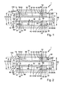
- Fig. 1 is a sectional view of an exemplary adjusting device according to the invention in a first position in a schematic representation
- FIG. 2 shows the design according to FIG. 1 in a second position
- Fig. 3 shows an exemplary adjusting device according to the invention, for example, the Adjusting device according to Figures 1 and 2 may be, in a schematic exploded view.
- Fig. 4 is an exemplary adjusting device according to the invention, for example, the Adjusting device according to FIGS. 1 and 2 and / or Fig. 3 may be, in a schematic three-dimensional View.
- Fig. 1 shows an exemplary design of an adjusting device according to the invention in cut view in a first position.
- Motor vehicle transmission adjusting device 1 has a first energy storage device 10 or a first elastic element 10 and a second energy storage device 12 and a second elastic element 12. Further, the motor vehicle transmission adjusting device 1 a threaded spindle 14, a nut 16 and a housing 18.
- the housing 18 has a third housing opening 20, on or in which a lid or a nozzle or a plug 22 is arranged, which for simplicity in the following as a lid 22 is designated, and in particular can be designed as a neck or plug.
- This cover 22 is adjustable. In the embodiment of FIG. 1, this cover 22 is detachable and detachable so that it can be completely removed from the rest of the housing 18. It can also be provided that this cover 22 in its dissolved or open position is still held on the housing 18.
- the lid 22 carries a thread 24 which is arranged with a housing 18 on Thread 26 is screwed.
- a thread 24 which is arranged with a housing 18 on Thread 26 is screwed.
- an adjustment device for adjusting the bias of the elastic members 10, 12 created.
- the lid 22 can serve for assembly or disassembly purposes.
- an adjustability of the bias of the elastic Elements 10, 12 can be achieved in other ways.
- can be provided be used to adjust the preload spacers that are in their Number can be varied to achieve different biases.
- Such Spacers may, for example, in the region of the respective elastic element 10, 12th be positioned.
- assembly or disassembly can - alternatively or additionally - be provided other configurations, such as a housing pitch or like.
- the thread 26 arranged on the housing 18 is in the third housing opening 20 provided internal thread.
- the worn by the cover 22 thread 24 is designed in FIG. 1 as an external thread and can be screwed to the internal thread 26 become.
- the recorded in the third housing opening 20 cover or nozzle 22 forms a Housing wall or a second housing wall portion 28 of the housing 18.
- the lid 22 is provided with an opening 30 which serves as a through hole or passage opening 30 is designed, and forms a second housing opening 30.
- This second housing opening 30th is in the embodiment of FIG. 1 substantially concentric with the thread 24 of the lid or socket 22, so that the second housing opening 30 in different Positions or screw positions of the lid 22 retains its radial position.
- a first housing opening 34 is provided, which serves as a passage opening or Through hole 34 is designed.
- first housing opening 34 is concentric with the opposite housing wall or in the lid 22 provided second housing opening 30 is arranged.
- the second 30 and the first housing opening 34 are each designed cylindrical and have the same inner diameter. But it can Also be provided different inner diameter.
- these openings 30, 34 also have other opening cross-sections and / or be designed stepped.
- a lid or a nozzle or a plug is provided, in which the first housing opening 34 is arranged.
- This one may be in terms of its design and arrangement, for example, as described with respect to the lid 22. It can therefore be provided that in the opposite housing wall sections 28, 32 each have a lid is provided which is provided with an opening and optionally is screwed in the housing 18.
- a first chamber 36 is arranged or is formed.
- This chamber 36 may be, for example, a substantially cylindrical interior.
- the Housing openings 30, 34 open into this chamber 36.
- the chamber 36 is in the design of FIG. 1 - apart from the housing openings 30, 34 - substantially closed.
- the housing 18 can also be designed differently be. It can be provided, for example, that the housing in the region of the chamber Has 36 axial limits, which are connected by axially extending webs.
- the threaded spindle 14 has a thread 38 which is designed as an external thread.
- the nut 16 has a thread 40 which is designed as an internal thread.
- the mother 16 For example, it may be designed to have a cylindrical portion 42 as well one or more radially projecting from this cylindrical portion 42 annular flanges 44, 46.
- the nut 16 may be configured to be cylindrical and having a substantially constant outer diameter, or otherwise.
- annular flanges 44, 46 are provided, which in Substantially disposed at the two axial ends 48, 50 of the cylindrical portion 42 are.
- These annular flanges 44, 46 have axial projections 52, 54.
- These axial projections 52, 54 extend from the respective annular flanges 44, 46 axially in the respective other annular flange 44, 46 facing away.
- the axial projections 52, 54 are radial outside the respective annular flange 44, 46 arranged.
- the axial projections 52, 54 can for example, be cylindrically shaped.
- the first axial projection 52 which is arranged on the first annular flange 44, adjoins a first recess 56 of the nut 16.
- the second axial projection 54, on the second annular flange 46 is adjacent to a second recess 58 of the nut 16.
- the depressions 54, 58 are cylindrical and over the provided with the thread 40 passage opening 59 of the mother 16 connected.
- the nut 16 may for example - in particular apart from the thread - rotationally symmetrical be designed.
- the mother can also be designed in a different form. It can also be provided that it has elements or grooves or the like, which, for example Part of an anti-rotation, which the housing 18 opposite the mother 16 secures against twisting.
- the mother 16 may, for example, apart of elements or grooves that are part of a rotation, and apart from Be designed thread rotationally symmetrical.
- the first elastic element 10 and the second elastic element 12 may be made of metal or plastic or other elastic material.
- the first energy storage or the first elastic element 10 and the second energy store or the second elastic Element 12 is shown in FIG. 1 as a spring or plate spring 60, 62 permitted. It can also be provided that energy storage or elastic elements 10, 12 are provided are, which are not disc springs, such as plastic blocks, coil springs or the like.
- the first plate spring 60 and the second plate spring 62 are each designed annular, so that they each have a passage opening 64 and 66, respectively.
- the threaded spindle 14 is rotatably mounted. For this purpose, suitable storage means be provided.
- the threaded spindle 14 is also mounted axially fixed. She can look after her Turn longitudinal axis or axis of rotation or be rotated, either in one or the opposite direction of rotation.
- the threaded spindle 14 can with the Output shaft of an electric motor be coupled to the threaded spindle 14 accordingly driving or driving can drive.
- an electronic control unit may be provided be that drives the electric motor.
- the threaded spindle 14 extends through the second through-opening 30 of the housing 18 and the lid 22 and through the first passage opening 34 in the lid 22nd opposite housing wall or housing wall portion 32 of the housing 18 is provided is.
- the threaded spindle 14 engages with its thread 38 in the thread 40 of the nut 16, so the threaded spindle 14 can drive the nut 16 in a driving manner.
- the nut 16 is movably arranged and can travel along the threaded spindle 14 is So relative to the threaded spindle 14 arranged relatively movable.
- the first elastic element 10 which in the Design as shown in FIG. 1 is designed as a plate spring 60, arranged so that the nut 16th the housing 18 in a first orientation of the axial direction, by the arrow 68 schematically is indicated, can load on the first elastic element 10 drivingly.
- first elastic element 10 or the Belleville spring 60 axially between a region of the nut 16, the - as shown in Fig. 1 - first annular flange 44 of the nut 16 may be or an end face of the nut 16, and a portion of the housing 18, which - as shown in Fig. 1 - the housing portion 32nd can be arranged.
- the first elastic element 10 or the one contacted Plate spring 60 in the unloaded rest position axially this area of this nut 16 and the first annular flange 44 of the nut 16 and this area of the housing 18 and the housing portion 32.
- the mother 16, the housing 18 is already driving over the first elastic element 10 and the plate spring 60 in the first orientation 64 of the axial direction load when the threaded spindle 14 starts from an unloaded rest position, driving the nut 16 in the direction of the arrow 68.
- the first plate spring 60 is received in the first recess 56 of the nut 16.
- the outer dimension or the outer diameter 70 of the first disc spring 60 is smaller than the outer diameter or the outer dimension 72 of the nut 16 and the first annular flange 44 of the nut 16.
- the first plate spring 60 is from the first annular flange Held 44 and supports with its radially outer region radially inward the first axial projection 52 from. It can also be secured there, for example clamped, be.
- first stop means 74 The deformation of the first elastic member 10 and the spring travel of the first Spring or first plate spring 60 is limited by a first stop means 74.
- the first spring or first plate spring 60 is arranged so that they are in the Operation is loaded on pressure or can be compressed or acts as a compression spring. there is the way or the amount to or to which this spring can be compressed limited.
- first surface area 76 of the Housing 18 in cooperation with a first surface portion 78 of the nut 16 as Slings act.
- This first surface area 76 of the housing 18 is on the inside of the housing on the first housing wall or the first housing wall section 32 arranged and the first surface portion 78 of the nut 16 is an end face 80 of the first axial projection 52.
- the second elastic element 12 is designed as a plate spring 62 in the design shown in FIG. 1, arranged so that the nut 16 the housing 18 in a second, the first opposite, orientation of the axial direction, which is indicated schematically by the arrow 82, via the second elastic element 12 can tax.
- second elastic element 12 or the Belleville spring 62 axially between a region of the nut 16, the -.
- second annular flange 46 of the nut 16 may be or an end face of the nut 16, and a portion of the housing 18 which, as shown in FIG. 1, may be the lid 22, is arranged.
- the second elastic element 12 or the one contacted Plate spring 62 in the unloaded rest position axially the area of this nut 16 and the second annular flange 46 of the nut 16 and this area of the housing 18 and the lid 22.
- the nut 16, the housing 18 is already driving on the second elastic Load element 12 or plate spring 62 in the second orientation 82 of the axial direction, when the threaded spindle 14 starts from an unloaded rest position, the nut 16 in the direction of arrow 82 impelling to load.
- the second plate spring 62 is received in the second recess 58 of the nut 16.
- the outer dimension or the outer diameter 84 of the second Plate spring 62 is smaller than the outer diameter or the outer dimension 86 of the nut sixteenth or the second annular flange 46 of the nut 16.
- the second plate spring 62 is of the second axial projection 54 is held or supported with its radially outer region radially inward from the second annular flange 46. It can also be secured there, for example be clamped.
- the deformation of the second elastic member 12 and the spring travel of the second spring or second plate spring 62 is limited by a second stop means 88 is.
- the second spring or second disk spring 62 is arranged in such a way that that it is subjected to pressure during operation or can be compressed or as Compression spring acts. In this case, the way or the measure is compressed or to which this spring can be limited.
- a second surface area 90 of the Housing 18 in cooperation with a second surface portion 92 of the nut 16th act as a stop means.
- This second surface area 90 of the housing 18 is on the Housing inside of the second housing wall and the second housing wall portion 28th and the lid 22 and the second surface portion 92 of the nut 16 is a End face 94 of the second axial projection 54th
- the housing 18 is arranged relative to the nut 16 movable relative. Furthermore, that is Housing 18 movably arranged.
- the nut 16 is guided on the housing 18. This is so that the first 44 as well as the second Ring flange 46 of the nut 16 and the first axial projection 52 and the second axial projection 54 are supported radially on the outside of the housing. It can also be provided that the axial clearance between the annular flanges 44, 46 is filled with material or the Nut 16 has a substantially constant outer diameter, and the mother 16th is supported on the housing 18 with this radially outer region. It can be radial There may also be some play between the nut 16 and the housing 18.
- the elastic elements 10 and 12 and the disc springs 60, 62 and the nut 16 are housed in the housing 18 and in the chamber 36 of the housing 18.
- the mother 16 is in Mother housing or housing 18 caught, in particular axially.
- the mother 16 is in Substantially disposed axially between the disc springs 60, 62.
- the elastic elements 10 and 12 and the disc springs 60, 62 are biased. These Bias is adjustable in the design of FIG. 1.
- By further screwing the cover 22 in the housing can be the bias of the elastic elements 10 and 12 or disc springs 60, 62 increase.
- the disc springs 60, 62 biased to a predetermined extent by the extent of the depth in which the lid or the plug 22 is inserted into the housing 18 or is screwed in.
- no bias voltage is generated or the elastic elements 10 and 12 or the disc springs 60, 62 optionally in the unloaded Hibernate with game are arranged. This can also be preferred by means of reach the lid 22.
- the stop positions the stop means 74 and / or 88 are adjustable.
- an adjustment be provided.
- This can for example also be such that the stop position is adjustable from the outside.
- a screw may be provided in each case from the outside in the first and second housing wall and the first and second housing wall portion 32, 28 and cover 22 is screwed in one place, on the end face 80 and 94 of the first and second axial projection 52, 54 is moved, so that this end face 80 or 94 or this projection instead of the inner surface of the first or the second housing wall or of the first or second housing wall section 32, 28 Cover 22 abuts against the screw shaft end of this screw, whose position can be changed by screwing.
- the axial Projections 52, 54 each in a corresponding annular groove in the lid 22 and in the first or second housing wall 32, immerse 28 and in this annular groove from the outside an adjustable Screw for setting the stop position opens. It can also be provided that only the first or only the second stop means with respect to their stop position are adjustable, or both.
- the values of the preload, the compression rate or spring rate and the mechanical Stops 74, 88 can also by the choice of different or different elastic Elements 10, 12 and disc springs 60, 62 are changed.
- the nut 16 opposite the housing 18 is secured by means of a rotation against relative rotation.
- the nut 16 radially outward or on the inside of the housing be provided in the axial direction extending groove, and on the other part a key or the like, so that the nut 16 and the housing 18 in the axial direction are arranged relatively movable, and are rotatably coupled with respect to their longitudinal axis.
- actuation or switching elasticity is not in all situations or under is desired in all conditions. It may be that no elasticity or actuation or Switching elasticity is desired when low forces are used or act. Corresponding it may be undesirable for a pronounced elastic movement to take place, when large loads or forces act.
- Fig. 1 a position is shown, which is given when low forces from the nut 16 on the housing 18 are transferred.
- the springs 60, 62 are biased.
- the spring 60 transmits the load or load from the nut 16 on the housing 18 without deforming or to deform significantly.
- the extent to which deform the first elastic member 10 and the plate spring 60 can or can be compressed or compressed can, is limited. This limitation takes place via the first stop means 74.
- FIG. 2 now shows this design in a fully compressed Position or in a fully compressed state, in which the first stop means 74 are in a stop position.
- the first surface area 78 of the nut 16 contacted - in the given in Fig. 2 accordingly the first surface portion 76 of the housing 18th
- the second elastic element 12 or second plate spring lies 62 here but no longer both on the nut 16, as well as on the housing 18 and the housing cover 22 on. But it can also be provided that spring elements used be, in which a concern would be given here or that the lid 22 accordingly further screwed into the housing 18.
- the plate spring 60 is in the stop position in Essentially completely absorbed in the recess 56 of the nut 16.
- the deformation or spring travel of the first elastic element 10 or the first Disk spring 60 is, as already mentioned, limited. This limit is such that the spring 60 can not be fully compressed, or can go to block, but before is limited by means of the aforementioned stop means the spring travel.
- the complete compressed position, which was addressed above, is thus, in which in one of the both possible load directions the spring is compressed to the maximum, which does not mean that the spring itself, if used in other applications, would not work would compress further.
- FIG. 3 shows an exemplary motor vehicle transmission adjusting device according to the invention in FIG schematic exploded view. This design can be in particular as it is based 1 and 2 has been described.
- FIG. 3 shows that the threaded spindle 14 has a connection region 120.
- This connection region 120 can be connected to a drive device become.
- a drive device is preferably an electric motor.
- the threaded spindle 14 rotatably on the connection area 120 is coupled to the motor output shaft of an electric motor. It can also be provided be that translation stages between such an engine output shaft and this Connection area 120 are provided.
- the threaded spindle 14 is the motor output shaft at the same time. It is specifically intended that a Such electric motor can drive the threaded spindle 14 in both directions of rotation, or optionally in one or the other. It can be provided, for example, that the electric motor can be switched accordingly.
- the threaded spindle 14 extends in the assembled state through the chamber 36 and by the housing 18. Parallel to the central axis 122 of the mounted threaded spindle 14 has the housing has a passage opening 124 arranged outside the chamber 36. These Through opening 124 is part of a rotation or a linear guide for the housing 18 and serves to receive a guide rod, the example in FIG. 4th is shown. Between the provided with this passage opening 124 housing portion 126 and the housing portion 128, in which the chamber 36 is arranged, is a housing portion 130 is provided, which has a toothing 132 and a rack 134.
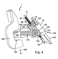
- FIG. 4 shows an exemplary design of a transmission actuating device according to the invention or adjusting device in a three-dimensional schematic view.
- the shown in Fig. 4 Adjusting device may for example also be designed as it is based on the Fig. 1 and Figure 2 and / or as explained with reference to Figure 3.
- This gear segment 152 is rotatably connected to a switching shaft 154, which in turn rotationally fixed to a shift finger 156 is arranged.
- the toothing 150 or the gear segment 152, in which or which the toothing 132 and the rack 134 engages, is provided directly on the shift finger 156.
- the housing 18 has an anti-rotation lock 158.
- This rotation lock 158 is like this substantially preventing the housing 18 from pivoting about the longitudinal axis 122 of FIG Spindle 14, or an axis parallel thereto, can be rotated.
- This rotation lock 158 has a through opening 124, already mentioned in FIG. 3, in which a Guide rod 160 is added.
- the guide rod 160 is preferably fixedly mounted, for example, on a housing that is different from the housing 18 and against which the housing 18 is movably arranged.
- the guide rod 160 is received in the in the through hole 124 of the housing 118.
- the passage opening 124 of the housing 18 and the housing 18 is axially movable on the guide rod 160 arranged.
- the guide rod 160 may also be in the through hole 124 of the housing 118 may be arranged that this arrangement alone a rotational mobility of the housing 118 would allow for the guide rod 160, but which thereby prevents housing 18 at a second location, in particular in the area of Chamber, also held.
- the guide rod 160 is substantially parallel to the Longitudinal axis 122 of the spindle 14 is arranged.
- the gear segment 152 is designed in a substantially quarter-circle, or a quarter-circular gear segment; this part can also be called a quadrant. But it can also cover a different angle range, such as a third circle or another segment part. But it can also be a gear.
- the shift finger 156 is arranged to be within an inner profile 164 or a passage opening given in the axial direction, the side is open, a shift rail 166 is arranged.
- the Shifting rail 166 axially or in the longitudinal direction of this shift finger 156, which by the arrow 186 schematically indicated, moved or loaded.
- This can, for example, a Synchronization ring or the synchronization of a transmission loaded or operated or switched to a gear in the transmission.
- Fig. 4 in a partial schematic view in particular a Getriebebetuschists- or gear shifting device shown. From Fig. 4 shows in particular how the Housing 18, the shift finger 156 and the shift rail 166 moves. In particular, there is also shown that in the housing 18, a rack is integrated, which is a quadrant or a provided with quadrant teeth or gear segment, a shift shaft and the shift finger 156 moves or pivots.
- the shift finger 156 pushes against an inner profile of the shift rail, or is the Shift finger 156 against an inner profile of the shift rail 156 is moved or pushed, and the shift finger 156 moves this shift rail 156 linearly.
- a plurality of shift rails or the like may be arranged.
- several such Shift rails be arranged substantially parallel, in such a way that in a neutral position a respective shift rail of the shift finger axially through the corresponding openings can be moved in the shift fingers.
- By selecting the appropriate position can be “selected”, which shift rail in a subsequent switching operation by means of a to be actuated in Fig. 4 adjusting device.
- a additional adjusting device is provided which this longitudinal displacement of the shift finger 156 in the direction of the switching shaft 154 can cause.
- This second adjusting device can also be designed in a different way than the inventive design of a control device. It can also be provided that such an additional adjusting device a Electric motor has. Such additional job direction can cause the Switching shaft 154 can be moved in its axial direction. It can also be designed that is moved, that the shift finger 156 are moved axially along the switching shaft 154 can.
Abstract
Description
Die Erfindung betrifft eine Kraftfahrzeuggetriebe-Stellvorrichtung zum Erzeugen von Stellbewegungen für Gangwechselvorgänge eines Kraftfahrzeuggetriebes, welche elastische Elemente aufweist, eine Verwendung einer solchen, sowie eine Kraftfahrzeuggetriebeeinrichtung mit einer solchen Kraftfahrzeuggetriebe-Stellvorrichtung.The invention relates to a motor vehicle transmission adjusting device for generating Actuating movements for gear change operations of a motor vehicle transmission, which elastic Has elements, a use of such, as well as a motor vehicle transmission device with such a motor vehicle transmission actuator.
Kraftfahrzeuggetriebe-Stellvorrichtungen bzw. Kraftfahrzeuggetriebe-Betätigungsvorrichtungen mit einer Stellvorrichtung, die ein elastisches Element aufweist, sind bereits aus den US-Patenten 6,003,395; 6,220,109 B1 sowie 6,003,649 bekannt. Dort werden insbesondere automatisierte Schaltgetriebe (ASG) mit einer derartigen Stellvorrichtung beschrieben. Das elastische Element kann Energie speichern. Aus diesen Druckschriften ist beispielsweise bekannt, dass ein elastisches Element in der Kraftübertragungsstrecke zwischen einem Betätigungs- bzw. Antriebselement und einem getriebeseitigen Schaltelement angeordnet wird. Ferner ist bekannt, dass ein solches elastisches Element voreinstellbar ist, d.h., dass seine Elastizität verändert werden kann, und vorgespannt ist (US 6,003,649). Weiter ist aus der US 6,003,649 bekannt, einen Anschlag vorzusehen, der die Verformung des elastischen Elements begrenzen kann.Motor vehicle transmission actuators or motor vehicle transmission actuators with an actuator having an elastic member are already off U.S. Patents 6,003,395; 6,220,109 B1 and 6,003,649 known. There will be in particular automated manual transmission (ASG) described with such a control device. The elastic element can store energy. From these documents, for example known that an elastic element in the power transmission path between an actuating or drive element and a transmission-side switching element is arranged. Furthermore, it is known that such an elastic element is presettable, that is, that its Elasticity can be changed, and is biased (US 6,003,649). Next is from the US 6,003,649 known to provide a stop, which is the deformation of the elastic element can limit.
Derartige Kraftfahrzeug-Stelleinrichtungen mit einem elastischen Element können auch als so genannte Schaltelastizitätseinheiten (Shift Elasticity Unit) bezeichnet werden.Such motor vehicle actuating devices with an elastic element can also be used as such referred to as switching elasticity units (Shift Elasticity Unit).
Die US 6,003,649 zeigt zu verschiedene Darstellungen von Gestaltungen, bei denen eine Elastizität bzw. ein elastisches Element vorgesehen ist. Ferner sind in den genannte Druckschriften verschiedene Kraft-Weg-Verläufe dargestellt, die das Verhalten bei Verwendung der jeweiligen elastischen Elemente abbilden (US 6,003,649, US 6,220,109). Die US 6,003,649 sowie die US 6,220,109 nennen verschiedene Arten und Materialien solcher elastischer Elemente. Insbesondere werden dort auch verschiedene Federarten genannt, die verwendet werden können um die Elastizität zu bewirken.US 6,003,649 shows various representations of designs in which a Elasticity or an elastic element is provided. Further, in the cited documents different force-displacement curves are shown, which show the behavior when using the Represent respective elastic elements (US 6,003,649, US 6,220,109). US 6,003,649 and US 6,220,109 mention various types and materials of such elastic elements. In particular, there are also called different types of springs that used can be to cause the elasticity.
In den Figuren der genannten Patentschriften sind ferner Gestaltungen gezeigt, die Vorschläge dafür beinhalten, wie solche Stellvorrichtungen bzw. Betätigungsvorrichtungen in einem Kraftfahrzeuggetriebe bzw. ein automatisiertes Schaltgetriebe gestaltet und angeordnet werden können. In the figures of said patents further designs are shown, the Suggestions include how such actuators or actuators in designed and arranged a motor vehicle transmission or an automated transmission can be.
Die dort gezeigten Gestaltungen sind besonders für automatisierte Schaltgetriebe geeignet.The designs shown there are particularly suitable for automated manual transmission.
Der Erfindung liegt die Aufgabe zugrunde, eine Kraftfahrzeuggetriebe-Stellvorrichtung zum Erzeugen von Stellbewegungen für Gangwechselvorgänge eines Kraftfahrzeuggetriebes zu schaffen, welche betriebssicher und kostengünstig herstellbar ist.The invention has for its object to provide a motor vehicle transmission actuator for Generating adjusting movements for gear change operations of a motor vehicle transmission to create, which is reliable and inexpensive to produce.
Gemäß einem besonderen Aspekt liegt der Erfindung die Aufgabe zugrunde, eine Kraftfahrzeuggetriebe-Stellvorrichtung zu schaffen, die sich für Erzeugen von Stellvorgängen im Rahmen von Gangwechselvorgängen in Parallelschaltgetrieben eignet.According to a particular aspect, the invention is based on the object, a To provide motor vehicle transmission actuating device, which is suitable for generating actuating operations in the context of gear changes in parallel transmissions suitable.
Erfindungsgemäß wird insbesondere eine Kraftfahrzeuggetriebe-Stellvorrichtung zum Erzeugen von Stellbewegungen vorgeschlagen, welche eine beweglich angeordnete Gewindespindel aufweist, die mit ihrem Gewinde in ein Gewinde einer beweglich angeordneten Mutter eingreift, so dass diese Gewindespindel diese Mutter belasten bzw. treibend belasten kann, und welche ferner ein beweglich sowie gegenüber der Mutter relativbeweglich angeordnetes Gehäuse aufweist, sowie zwei elastische Elemente, wobei ein erstes dieser elastischen Elemente so zwischen der Mutter und dem Gehäuse angeordnet ist, dass die Mutter das Gehäuse in einer ersten Orientierung ihrer Axialrichtung über dieses erste elastische Element belasten bzw. treibend belasten kann, und wobei das zweite dieser elastischen Elemente so zwischen der Mutter und dem Gehäuse angeordnet ist, dass die Mutter das Gehäuse über dieses zweite elastische Element in einer zweiten, der ersten entgegen gesetzten, Orientierung ihrer Axialrichtung belasten bzw. treibend belasten kann.According to the invention, in particular a motor vehicle transmission adjusting device for Generating adjusting movements proposed which a movably arranged threaded spindle having, with its thread in a thread of a movably arranged nut engages, so that this threaded spindle load this nut or impelling driving can, and which is also a movable and relative to the mother arranged relatively movable Housing, as well as two elastic elements, wherein a first of these elastic Elements arranged between the nut and the housing so that the nut is the housing load in a first orientation of its axial direction via this first elastic element or drivingly charged, and wherein the second of these elastic elements so between the mother and the housing is arranged, that the mother over the housing over this second elastic element in a second, the first opposite, orientation burden their axial direction or can impose a driving burden.
Vorzugsweise lassen sich mit der Kraftfahrzeuggetriebe-Stellvorrichtung Stellbewegungen für Gangwechselvorgänge eines Kraftfahrzeuggetriebes erzeugen.Preferably can be with the motor vehicle actuator actuating movements for Generate gear change operations of a motor vehicle transmission.
Es kann vorgesehen sein, dass zwischen der Kraftfahrzeuggetriebe-Stellvorrichtung und dem Getriebe weitere Bauelement vorgesehen sind.It can be provided that between the motor vehicle transmission adjusting device and the Transmission further component are provided.
Bevorzugt ist die Gewindespindel drehbeweglich angeordnet bzw. gelagert bzw. drehbeweglich und axialfest.Preferably, the threaded spindle is rotatably arranged or mounted or rotatably movable and axially resistant.
Bevorzugt ist vorgesehen, dass das erste bzw. zweite elastische Element jeweils so zwischen der Mutter und dem Gehäuse angeordnet ist, dass die Mutter das erste bzw. zweite elastische Element, abhängig von der Bewegungsrichtung der Mutter, sofort belastet, wenn die Mutter bewegt wird. Es kann allerdings auch vorgesehen sein, dass ein gewisses Spiel bzw. eine Art Leerhub vorgesehen ist, welcher bewirkt, dass die Mutter zunächst bewegt wird, ehe sie das jeweilige elastische Element belastet und über die Belastung dieses elastischen Elements wiederum das Gehäuse in der einen oder anderen Axialrichtung belastet wird.It is preferably provided that the first and second elastic element in each case so between the nut and the housing is arranged, that the mother the first and second elastic Element, depending on the direction of movement of the mother, immediately charged when the mother is moved. However, it can also be provided that a certain game or a kind Leerhub is provided, which causes the mother is first moved before they respective elastic element loaded and over the load of this elastic element in turn, the housing is loaded in one or the other axial direction.
Bevorzugt weist das Gehäuse in zwei gegenüberliegenden Gehäusewänden bzw. Gehäusewandabschnitten jeweils eine Öffnung, insbesondere Durchgangsöffnung, auf, wobei sich die Gewindespindel durch diese beiden Durchgangsöffnungen erstreckt. Solche Durchgangsöffnungen können beispielsweise in einer Gehäusewand- oder Gehäuseschale angeordnet sein. Bevorzugt ist ferner, dass solche Durchgangsöffnungen in einem Gehäusedeckel bzw. Stutzen bzw. Pfropfen angeordnet sind, der in das (verbleibende) Gehäuse eingesetzt oder eingeschraubt ist.Preferably, the housing in two opposite housing walls or Housing wall sections each have an opening, in particular through opening, on, wherein the threaded spindle extends through these two through holes. Such through holes For example, they can be arranged in a housing wall or housing shell be. It is further preferred that such passage openings in a housing cover or nozzles or plugs are arranged, which are inserted into the (remaining) housing or screwed in.
Ein solcher Deckel kann insbesondere auch als Stutzen bzw. Pfropfen gestattet sein. Zur Vereinfachung wird im folgenden von Deckel bzw. Gehäusedeckel gesprochen, wobei anzumerken ist, dass vorzugsweise ein solcher (Gehäuse)Deckel ein Stutzen bzw. Pfropfen ist, so dass der Begriff (Gehäuse)Deckel weit gefasst zu verstehen ist, und insbesondere einen Stutzen bzw. Pfropfen mit abdeckt.Such a lid may in particular also be permitted as a nozzle or plug. to Simplification is spoken in the following of the lid or housing cover, to be noted is that preferably such a (housing) cover is a nozzle or grafting, so that the term (housing) cover is to be understood broadly, and in particular a nozzle or grafting with covers.
Der angesprochene Deckel kann insbesondere ein lösbarer Deckel sein. Die Lösbarkeit kann insbesondere so sein, dass der Deckel eine Öffnung im Gehäuse verschließen bzw. teilweise verschließen kann oder freigeben kann.The addressed lid may in particular be a detachable lid. The solubility can in particular be such that the lid close an opening in the housing or partially can close or release.
In einer bevorzugten Gestaltung weist ein solcher Deckel auf seiner Außenmantelfläche ein Gewinde auf, mit dem es in eine Öffnung im Gehäuse geschraubt ist, die ebenfalls ein Gewinde aufweist. Es ist vorzugsweise vorgesehen sein, dass sich die Spindel an zwei Stellen aus dem Gehäuse raus erstreckt, wobei an diesen Stellen jeweils ein abnehmbarer bzw. lösbarer Deckel vorgesehen ist, der mit einer Durchgangsöffnung versehen ist, und in das Gehäuse geschraubt ist, oder auf andere Weise dort lösbar befestigt ist.In a preferred embodiment, such a cover on its outer circumferential surface Thread on, with which it is screwed into an opening in the housing, which is also a thread having. It is preferably provided that the spindle is in two places the housing extends out, in each case a removable or detachable at these locations Cover is provided, which is provided with a passage opening, and in the housing screwed, or otherwise releasably secured there.
Es kann aber auch vorgesehen sein, dass nur ein Deckel der genannten Art vorgesehen ist, und die Gewindespindel sich an einer anderen Stelle durch eine in einer festen Gehäusewand angeordnete Durchgangsöffnung des Gehäuses erstreckt. But it can also be provided that only a lid of the type mentioned is provided, and the threaded spindle at another location by one in a fixed housing wall arranged through opening of the housing extends.
Bevorzugt ist ferner, dass sich die Gewindespindel an zwei Stellen aus dem Gehäuse erstreckt, wobei an keiner dieser Stellen ein Gehäusedeckel der genannten Art vorgesehen ist.It is further preferred that the threaded spindle at two points out of the housing extends, provided at any of these locations a housing cover of the type mentioned is.
Vorzugsweise ist das Gehäuse mittels einer Verdrehsicherung gegen Verdrehung gesichert. Eine solche Verdrehsicherung kann beispielsweise eine Linearführung aufweisen. In einer bevorzugten Gestaltung ist eine derartige Linearführung so angeordnet, dass sie eine im Wesentlichen parallel zur Spindel angeordnete Führungsstange aufweist, die zur Spindel beabstandet ist und sich durch das Gehäuse erstreckt. Die Führungsstange erstreckt sich beispielsweise so durch das Gehäuse bzw. eine Gehäuseöffnung, dass sie ihren radialen Richtungen bzw. in radialer Richtung - gegebenenfalls mit geringem Spiel - am Gehäuse gehalten wird. Besonders bevorzugt stützt sich dabei die Gewindespindel - gegebenenfalls über die Mutter - so gegen das Gehäuse ab, dass das Gehäuse bzgl. der radialen Richtung bzw. den radialen Richtungen der Gewindespindel - gegebenenfalls mit geringem Spiels - an dieser gehalten wird. Es kann beispielsweise vorgesehen sein, dass zur Aufnahme dieser Führungsstange eine separate Durchgangsöffnung oder mehrere separate Durchgangsöffnungen im Gehäuse vorgesehen sind. Besonders bevorzugt sichert die Verdrehsicherung das Gehäuse gegen Verdrehung um die Spindelachse bzw. eine hierzu parallele Achse.Preferably, the housing is secured by means of a rotation against rotation. Such a rotation can, for example, have a linear guide. In a preferred Design is such a linear guide arranged so that it is a substantially parallel to the spindle arranged guide rod, which is the spindle is spaced and extends through the housing. The guide rod extends for example so through the housing or a housing opening that they are their radial directions or in the radial direction - optionally with little play - held on the housing becomes. Particularly preferably, the threaded spindle is supported - possibly via the Nut - so against the housing from that the housing with respect to the radial direction or the Radial directions of the threaded spindle - possibly with little play - on this is held. It can be provided, for example, that for receiving this guide rod a separate passage opening or a plurality of separate passage openings in Housing are provided. Particularly preferably, the anti-rotation device secures the housing against rotation about the spindle axis or an axis parallel thereto.
In einer bevorzugten Gestaltung ist das Gehäuse gegenüber der Mutter gegen Verdrehung gesichert. Eine solche Verdrehsicherung, mittels welcher die Mutter gegenüber dem Gehäuse gegen Verdrehung gesichert ist, kann beispielsweise so sein, dass diese Verdrehsicherung eine Längs- bzw. Axialverschiebung von Mutter gegenüber Gehäuse ermöglicht, allerdings ein Verdrehen im Wesentlichen verhindert. Beispielsweise kann eine Längsnut am Gehäuse vorgesehen sein, in welche eine an der Mutter angeordnete Passfeder eingreift, oder umgekehrt.In a preferred embodiment, the housing is against rotation with respect to the nut secured. Such a rotation, by means of which the nut relative to the housing secured against rotation, for example, be such that this rotation a longitudinal or axial displacement of mother to housing allows, however, a Twisting essentially prevented. For example, a longitudinal groove may be provided on the housing be, in which engages a arranged on the nut key, or vice versa.
In bevorzugter Gestaltung ist die Mutter in dem Gehäuse gefangen. Die Mutter kann beispielsweise axial gefangen sein. Sie kann auch radial gefangen sein. Besonders bevorzugt ist die Kombination dieser beiden Gestaltungen.In a preferred embodiment, the nut is trapped in the housing. The mother can for example, be caught axially. It can also be caught radially. Especially preferred is the combination of these two designs.
Bevorzugt ist das Gehäuse ein Gehäuse der Mutter bzw. eine die Mutter einschließendes oder fangendes Gehäuse.Preferably, the housing is a housing of the mother or a nut enclosing or catching housing.
In bevorzugter Gestaltung ist im Gehäuse eine Kammer vorgesehen, in welcher die beiden elastischen Elemente sowie die Mutter angeordnet sind. Besonders bevorzugt ist vorgesehen, dass in diese Kammer Durchgangsöffnungen des Gehäuses münden, durch welche sich die Gewindespindel erstreckt. Bevorzugt ist ferner, dass eine Führungsstange einer Verdrehsicherung für das Gehäuse sich durch das Gehäuse erstreckt, und zwar außerhalb einer Kammer der angesprochenen Art.In a preferred embodiment, a chamber is provided in the housing, in which the two elastic elements and the nut are arranged. Particularly preferred is provided that through openings of the housing open into this chamber, through which the Threaded spindle extends. It is further preferred that a guide rod an anti-rotation for the housing extends through the housing, outside a chamber of the kind addressed.
In einer bevorzugten Gestaltung ist das Gehäuse mit wenigstens einer Schaltwelle gekoppelt. Dies kann eine direkte oder eine indirekte Kopplung sein, also so gestaltet sein, dass das Gehäuse direkt, beispielsweise über eine Verzahnung oder dergleichen, in eine Schaltwelle bzw. eine dort angeordnete Verzahnung eingreift, oder so, dass Elemente zwischengeschaltet sind. Vorzugsweise ist vorgesehen, dass das Gehäuse eine solche Schaltwelle treibend belasten kann. Bevorzugt ist ferner, dass das Gehäuse mit wenigstens einem Schaltfinger gekoppelt ist, wobei auch hier die Kopplung direkt oder indirekt sein kann. Auch hier ist besonders bevorzugt, dass das Gehäuse den Schaltfinger treibend belasten kann. Das Gehäuse ist bevorzugt relativbeweglich gegenüber der Schaltwelle und / oder dem Schaltfinger angeordnet. Bevorzugt ist ferner, dass das Gehäuse fest mit der Schaltwelle und / oder dem Schaltfinger verbunden ist. Ein solcher Schaltfinger ist in besonders bevorzugter Gestaltung an einer Schaltwelle der genannten Art angeordnet. In einer bevorzugten Gestaltung ist der Schaltfinger drehfest mit der Schaltwelle verbunden. Dabei kann er beispielsweise mit der Schaltwelle axiaffest gekoppelt sein, oder axial beweglich an dieser angeordnet sein.In a preferred embodiment, the housing is coupled to at least one shift shaft. This can be a direct or indirect coupling, so be designed so that the housing directly, for example via a toothing or the like, in a switching shaft or a toothing arranged there engages, or so that elements are interposed. Preferably, it is provided that the housing load such a switching shaft drivingly can. It is further preferred that the housing is coupled to at least one shift finger is, where also the coupling can be direct or indirect. Again, it is particularly preferable that the housing can drive the shift finger driving. The housing is preferred arranged relatively movable relative to the shift shaft and / or the shift finger. Prefers is further that the housing fixedly connected to the shift shaft and / or the shift finger is. Such a shift finger is in a particularly preferred design of a shift shaft arranged the said type. In a preferred embodiment, the shift finger rotatably connected to the shift shaft. He can axiaffest example, with the shift shaft be coupled, or axially movable to be arranged on this.
Das Gehäuse ist vorzugsweise mit einer Verzahnung versehen, und war besonders bevorzugt mit einer an der Gehäuseaußenseite angeordneten Verzahnung. Eine solche Verzahnung kann beispielsweise eine Zahnstange bzw. ein zahnstangenähnliches Element sein. Vorzugsweise greift eine solche am Gehäuse angeordnete Verzahnung bzw. eine solche Zahnstange in ein Zahnrad oder ein Zahnradsegment ein, um dieses in Betrieb zu belasten bzw. treibend zu belasten. Besonders bevorzugt ist ein solches Zahnradsegment bzw. ein solches Zahnrad an einer Schaltwelle oder an einem Schaltfinger angeordnet.The housing is preferably provided with a toothing, and was particularly preferred with a toothing arranged on the outside of the housing. Such a gearing may for example be a rack or a rack-like element. Preferably engages such a housing arranged on the toothing or such Rack into a gear or gear segment to load it into operation or to be charged. Particularly preferred is such a gear segment or such Gear arranged on a shift shaft or on a shift finger.
Das erste elastische Element ist in bevorzugter Gestaltung eine Feder. Ferner ist bevorzugt, dass das zweite elastische Element eine Feder ist. Es kann vorgesehen sein, dass eine solche Feder jeweils so angeordnet ist, dass sei als Druckfeder wirkt.The first elastic element is in a preferred design a spring. It is further preferred that the second elastic element is a spring. It can be provided that such Spring is arranged in each case so that acts as a compression spring.
In besonders bevorzugter Gestaltung ist das erste elastische Element eine Tellerfeder. Besonders bevorzugt ist ferner, dass das zweite elastische Element eine Tellerfeder ist. Es kann aber auch vorgesehen sein, dass elastische Elemente anderer Art vorgesehen sind. Die elastischen Elemente wirken in besonders bevorzugter Gestaltung im Betrieb als Energiespeicher bzw. als Energiespeicher, der Antriebsenergie bzw. einen Teil der Antriebsenergie speichert.In a particularly preferred embodiment, the first elastic element is a plate spring. It is further preferred that the second elastic element is a plate spring. It but can also be provided that elastic elements of other types are provided. The elastic elements act in a particularly preferred design in operation as energy storage or as energy storage, the drive energy or a part of the drive energy stores.
In einer besonders bevorzugten Gestaltung ist vorgesehen, dass das Gehäuse eine Verzahnung bzw. Zahnstange trägt, und diese Zahnstange bzw. diese Verzahnung in ein Zahnrad bzw. ein Zahnradsegment eingreift, welche an dem Schaltfinger und / oder an der Schaltstange angeordnet ist, so dass der Schaltfinger und / oder die Schaltstange im Betrieb treibend belastet werden können. In einer besonders bevorzugten Gestaltung ist vorgesehen, dass bei Axialverschiebung des Gehäuses ein solches Zahnrad bzw. Zahnradsegment schwenkend oder drehend bewegt wird. Bevorzugt ist ferner, dass der Schaltfinger eine Schaltschiene belasten kann bzw. im Betrieb treibend belastet oder bei entsprechender Relativstellung treibend belastet. Besonders bevorzugt ist vorgesehen, dass der Schaltfinger in einer Schwenkbewegung im Betrieb ausführt und über diese Schwenkbewegung eine solche Schaltschiene translatorisch in eine erste Richtung oder in eine zweite Richtung bewegen kann bzw. bewegt, bzw. entsprechend belasten kann, um eine derartige Bewegung hervorzurufen.In a particularly preferred embodiment, it is provided that the housing has a Gearing or rack carries, and this rack or these teeth in a Gear or a gear segment engages which on the shift finger and / or on the Shift rod is arranged so that the shift finger and / or the shift rod in operation can be charged. In a particularly preferred embodiment is provided that at axial displacement of the housing such a gear or gear segment is moved pivoting or rotating. It is further preferred that the shift finger a Can burden shift rail or loaded driving in operation or with appropriate relative position driving burdened. It is particularly preferred that the shift finger in a Swivel movement during operation executes and about this pivoting movement such Shift rail translationally move in a first direction or in a second direction can or, respectively, load accordingly, to cause such a movement.
Vorzugsweise ist das erste und / oder das zweite elastische Element vorgespannt.Preferably, the first and / or the second elastic element is biased.
Besonders bevorzugt ist eine Einstelleinrichtung vorgesehen, mittels welcher eine solche Vorspannung des ersten und / oder des zweiten elastischen Elements einstellbar ist. Es kann vorgesehen sein, dass eine Einstelleinrichtung so gestaltet ist, dass von der Gehäuseaußenseite diese Vorspannung einstellbar ist. In bevorzugter Gestaltung ist eine solche Einstelleinrichtung ein Gehäusedeckel der genannten Art, also ein solcher Deckel, der im Gehäuse verschraubt ist, und durch welchen sich gegebenenfalls die Gewindespindel erstreckt.Particularly preferably, an adjusting device is provided, by means of which such Bias of the first and / or the second elastic element is adjustable. It can be provided that an adjustment is designed so that from the outside of the housing this bias is adjustable. In a preferred embodiment, such an adjustment a housing cover of the type mentioned, that is, such a lid which is screwed in the housing is, and through which optionally extends the threaded spindle.
In bevorzugter Weiterbildung der Erfindung ist eine solche Einstelleinrichtung so gestaltet, dass durch sie gleichzeitig das erste und das zweite elastische Element eingestellt werden kann, bzw. die Vorspannung dieser Elemente gleichzeitig bzw. simultan eingestellt werden kann.In a preferred embodiment of the invention, such an adjustment is designed so that at the same time the first and the second elastic element are adjusted by them can, or the bias of these elements are set simultaneously or simultaneously can.
Vorzugsweise ist wenigstens ein erstes Anschlagmittel vorgesehen, durch welches der Verformungs- bzw. Federweg des ersten elastischen Elements bzw. der ersten elastischen Feder begrenzt ist. Es kann beispielsweise auch vorgesehen sein, dass ein solches erstes Anschlagmittel einstellbar ist, so dass die Anschlagposition eingestellt werden kann. Das erste Anschlagmittel ist vorzugsweise so, dass eine Anschlagposition erreicht ist, bevor das erste elastische Element sich maximal verformt hat bzw. maximal komprimiert ist, bzw. - insbesondere bei als Feder gestalteten erstem elastischem Element - die Feder ihren maximalen Federweg bzw. die minimale Federlänge erreicht hat. Beispielsweise kann dies so sein, dass die Feder eine Kompressionsfeder ist und die Anschlagmittel anschlagen bzw. in eine Anschlagposition gehen, bevor diese Feder völlig komprimiert ist.Preferably, at least one first stop means is provided, through which the Deformation or spring travel of the first elastic element or the first elastic Spring is limited. It can also be provided, for example, that such a first Slip means is adjustable so that the stop position can be adjusted. The first Lifting means is preferably such that a stop position is reached before the first elastic element has deformed a maximum or is compressed to the maximum, or - in particular when designed as a spring first elastic element - the spring their maximum travel or has reached the minimum spring length. For example, this may be the case Spring is a compression spring and strike the stop means or in a stop position go before this spring is completely compressed.
In entsprechender Weise kann auch ein zweites Anschlagmittel vorgesehen sein, das in gleicher bzw. entsprechender Weise gestaltet und / oder angeordnet ist wie das erste elastische Element, und das für das zweite elastische Element bzw. die zweite Feder vorgesehen ist.In a corresponding manner, a second stop means may be provided which in the same or corresponding manner designed and / or arranged as the first elastic Element, and provided for the second elastic member and the second spring is.
In bevorzugter Gestaltung weist die Mutter eine erste Vertiefung auf, in welcher das erste elastische Element aufgenommen wird. Es kann auch vorgesehen sein, dass die Mutter ergänzend oder alternativ eine zweite Vertiefung aufweist, in welcher das zweite elastische Element aufgenommen wird. Besonders bevorzugt ist an den beiden axialen Enden der Mutter jeweils eine Vertiefung vorgesehen, von denen eine erste Vertiefung ist, die das erste elastische Element bzw. die erste Feder aufnimmt, und die andere eine zweite Vertiefung ist, die das zweite elastische Element bzw. die zweite Feder aufnimmt. In besonders bevorzugter Gestaltung wirkt ein (jeweiliger) Oberflächenbereich der Mutter, der an eine derartige Vertiefung angrenzt, im Zusammenwirken mit einem Oberflächenabschnitt des Gehäuses, und zwar insbesondere einem auf der Innenseite des Gehäuses gelegenen Oberflächenabschnitt des Gehäuses, als erstes bzw. zweites Anschlagmittel.In a preferred embodiment, the nut has a first recess, in which the first elastic element is absorbed. It may also be provided that the mother is supplementary or alternatively, a second recess, in which the second elastic element is recorded. Particularly preferred is at the two axial ends of the nut each provided with a recess, one of which is a first recess, which is the first elastic Receives element or the first spring, and the other is a second recess, the receives the second elastic element or the second spring. In particularly preferred Design affects a (respective) surface area of the mother, to such a recess adjacent, in cooperation with a surface portion of the housing, namely in particular a surface portion of the housing located on the inside of the housing Housing, as the first and second stop means.
Das erste und / oder das zweite Anschlagmittel ist vorzugsweise ein mechanisches Anschlagmittel.The first and / or the second stop means is preferably a mechanical one Slings.
In bevorzugter Gestaltung wird die Mutter in ihrem radial äußeren Bereich am Gehäuse geführt, und zwar insbesondere axial geführt. Die Mutter kontaktiert vorzugsweise im Wesentlichen das Gehäuse mit ihrem radial äußeren Bereich, wobei gegebenenfalls geringes Spiel gegeben ist.In a preferred embodiment, the nut is in its radially outer region on the housing guided, in particular axially guided. The mother preferably essentially contacts the housing with its radially outer region, where appropriate, low clearance given is.
Die Gewindespindel ist in besonders bevorzugter Gestaltung axial fest um ihre Längsachse drehbeweglich gelagert.The threaded spindle is in a particularly preferred design axially fixed about its longitudinal axis rotatably mounted.
Vorzugsweise ist eine Antriebseinrichtung, wie beispielsweise ein Elektromotor, zum Antreiben der Gewindespindel vorgesehen. Eine solche Antriebseinrichtung kann direkt oder über weitere zwischengeschaltete Elemente mit der Gewindespindel gekoppelt sein. Bevorzugt kann die Drehrichtung der Motorausgangswelle einer als Elektromotor gestalteten Antriebseinrichtung umgeschaltet werden.Preferably, a drive device, such as an electric motor, for Driving the threaded spindle provided. Such a drive device can directly or be coupled via further intermediate elements with the threaded spindle. Prefers can the direction of rotation of the motor output shaft designed as an electric motor drive device be switched.
Bevorzugt ist ferner, dass ein elektronisches Steuergerät vorgesehen ist, mittels welchem der Elektromotor gesteuert werden kann. Ein solches elektronisches Steuergerät kann beispielsweise ein elektronisches Getriebesteuergerät sein.It is further preferred that an electronic control device is provided, by means of which the Electric motor can be controlled. Such an electronic control unit can, for example be an electronic transmission control unit.
Die erfindungsgemäße Gestaltung einer Stellvorrichtung, die auch als Schalt- bzw. Betätigungselastizitätsbaugruppe oder Schalt- bzw. Betätigungselastizitätseinheit oder - konstruktion bezeichnet werden kann, weist vorzugsweise die Charakteristiken bzw. Eigenschaften und Vorteile auf, die in den US-Patenten 6,003,395; 6,220,109 B1 sowie 6,003,649 in Bezug auf den Einsatz der elastischen Elemente genannt sind. Die erfindungsgemäße Gestaltung einer Stellvorrichtung ermöglicht durch ihrer Gestaltung und / oder die Anordnung ihrer Bauteile, dass sie auch für Getriebe eingesetzt werden kann, bei denen die bekannten Gestaltungen - aus Bauraumgründen oder dergleichen - weniger geeignet sind. Dies bedeutet allerdings nicht, dass die erfindungsgemäße Gestaltung diese Vorteile in jeder Ausgestaltung aufweisen muss; es wird vielmehr die Möglichkeit durch die Erfindung geschafften, derartige vorteilhafte Gestaltungen zu verwirklichen.The inventive design of an adjusting device, which is also known as switching or Actuating elasticity assembly or switching elasticity unit or construction, preferably has the characteristics and advantages disclosed in U.S. Patents 6,003,395; 6,220.109 B1 and 6,003,649 in terms of the use of elastic elements are called. The inventive design an actuator allows by their design and / or the arrangement of their Components that they can also be used for transmissions in which the known designs - For reasons of space or the like - are less suitable. This means, however not that the inventive design have these advantages in each embodiment got to; Rather, the possibility is achieved by the invention, such advantageous To realize designs.
Die erfindungsgemäße Stellvorrichtung bzw. die erfindungsgemäße Schaltelastizitätskonstruktion ist vorzugsweise so, das elastische Elemente an jedem der beiden Enden einer mit Gewinde versehenen Mutter verwendet werden, die Elastizität zu einem anliegenden Muttergehäuse absorbieren können bzw. gewährleisten können.The adjusting device according to the invention or the inventive Schaltelastizitätskonstruktion is preferably so, the elastic elements at each of the two ends of a threaded provided mother, the elasticity to an adjacent mother housing can be able to absorb or guarantee.
Erfindungsgemäß wird ferner insbesondere eine Kraftfahrzeug-Getriebeeinrichtung mit einer Betätigungseinrichtung zum Steuern von Gangwechselvorgängen der Kraftfahrzeug-Getriebeeinrichtung vorgeschlagen, wobei mittels dieser Betätigungseinrichtung ein jeweiliger Gang gewählt werden kann, in einen jeweiligen Gang der Kraftfahrzeug-Getriebeeinrichtung geschaltet werden und die Kraftfahrzeug-Getriebeeinrichtung in Neutral geschaltet werden kann, wobei diese Betätigungseinrichtung eine erfindungsgemäße Kraftfahrzeuggetriebe-Stellvorrichtung aufweist.According to the invention, in particular, a motor vehicle transmission device with a Actuating device for controlling gear change operations of the motor vehicle transmission device proposed, wherein by means of this actuator a respective Gear can be selected in a respective gear of the motor vehicle transmission device be switched and the motor vehicle transmission device are switched to neutral can, this actuator is a motor vehicle transmission adjusting device according to the invention having.
Diese Kraftfahrzeug-Getriebeeinrichtung ist vorzugsweise als automatisiert betätigbare Kraftfahrzeug-Getriebeeinrichtung gestaltet. Sie kann beispielsweise als automatisiertes Schaltgetriebe geschaltet sein. This motor vehicle transmission device is preferably operated as an automated Motor vehicle transmission device designed. It can be automated, for example Be switched manual transmission.
In besonders bevorzugter Gestaltung ist diese Kraftfahrzeug-Getriebeeinrichtung als Parallelschaltgetriebe (PSG) gestaltet. Besonders bevorzugt ist die Kraftfahrzeug-Getriebeeinrichtung ein Inline-Parallelschaltgetriebe. Es kann auch vorgesehen sein, dass die Kraftfahrzeug-Getriebeeinrichtung als unterbrechungsfreies Schaltgetriebe (USG) gestaltet ist.In a particularly preferred embodiment, this motor vehicle transmission device as Parallel gearbox (PSG) designed. Particularly preferred is the motor vehicle transmission device an inline parallel gearbox. It can also be provided that the Motor vehicle transmission device designed as an uninterruptible transmission (USG).
Erfindungsgemäß wird ferner insbesondere vorgeschlagen, eine Kraftfahrzeuggetriebe-Stellvorrichtung der erfindungsgemäßen Art und / oder eine Betätigungsvorrichtung mit einer eine Kraftfahrzeuggetriebe-Stellvorrichtung der erfindungsgemäßen Art zum Betätigen einer Kraftfahrzeug-Getriebeeinrichtung zu verwenden. Besonders bevorzugt ist dabei, dass eine solche Stellvorrichtung bzw. Betätigungsvorrichtung zum Betätigen einer Kraftfahrzeug-Getriebeeinrichtung verwendet wird, die ein Parallelschaltgetriebe (PSG) ist. Bevorzugt ist erfindungsgemäß eine Verwendung der erfindungsgemäßen Stellvorrichtung in einer Betätigungsvorrichtung für ein Inline-Parallelschaltgetriebe eines Kraftfahrzeuges, welches in besonders bevorzugter Gestaltung dergestalt ist, wie es in der Britischen Patentanmeldung 0223531.5 beschrieben wird. In besonders bevorzugter Gestaltung ist vorgesehen, dass eine erfindungsgemäße Kraftfahrzeuggetriebe-Stellvorrichtung zum Schalten in Gänge der Kraftfahrzeug-Getriebeeinrichtung verwendet wird. Es kann beispielsweise vorgesehen sein, dass das Schalten in die Gänge mittels einer erfindungsgemäßen Stellvorrichtung durchgeführt wird. Alternativ oder ergänzend kann auch vorgesehen sein, dass das Schalten in Neutral bzw. das Rausnehmen der Gänge mittels einer erfindungsgemäßen Stellvorrichtung durchgeführt wird.According to the invention, it is further proposed, in particular, a motor vehicle transmission adjusting device The inventive type and / or an actuating device with a a motor vehicle transmission adjusting device of the type according to the invention for actuating a Motor vehicle transmission device to use. It is particularly preferred that a Such adjusting device or actuating device for actuating a motor vehicle transmission device used, which is a parallel shift transmission (PSG). Preferred according to the invention a use of the adjusting device according to the invention in an actuating device for an inline parallel shift transmission of a motor vehicle, which in particular Preferred design is such as in the British patent application 0223531.5 is described. In a particularly preferred embodiment, it is provided that a Motor vehicle transmission adjusting device according to the invention for shifting in gears of the motor vehicle transmission device is used. For example, it may be provided that the switching into the gears carried out by means of an adjusting device according to the invention becomes. Alternatively or additionally, it can also be provided that switching in neutral or the taking out of the gears carried out by means of an adjusting device according to the invention becomes.
Eine erfindungsgemäße Stellvorrichtung kann allerdings auch dazu verwendet werden, das so genannte "Wählen" bei einer Kraftfahrzeug-Getriebeeinrichtung zu bewirken bzw. zu steuern. Es kann auch vorgesehen sein, dass eine erfindungsgemäße Stellvorrichtung sowohl zum "Wählen", als auch zum "Schalten" in einem Kraftfahrzeuggetriebe verwendet wird.However, an adjusting device according to the invention can also be used to do so effecting or controlling said "dialing" in a motor vehicle transmission device. It can also be provided that an adjusting device according to the invention both for "Select", as well as for "switching" is used in a motor vehicle transmission.
Die erfindungsgemäße Stellvorrichtung wird bevorzugt für Getriebebetätigungs- bzw. Getriebeschaltmechanismus verwendet, bei dem eine Gewindespindel zum Betätigen bzw. Schalten verwendet wird.The adjusting device according to the invention is preferred for Getriebeebetätigungs- or Gear shift mechanism used in which a threaded spindle for actuating or Switching is used.
Im Folgenden werden anhand der Figuren beispielhafte Gestaltungen und Weiterbildungen der Erfindung erläutert, wodurch die Erfindung allerdings nicht beschränkt werden soll. Es zeigt: In the following, exemplary designs and developments are based on the figures However, the invention should not be limited. It shows:
Fig. 1 eine Schnittansicht einer beispielhaften erfindungsgemäßen Stellvorrichtung in einer ersten Stellung in schematischer Darstellung;Fig. 1 is a sectional view of an exemplary adjusting device according to the invention in a first position in a schematic representation;
Fig. 2 die Gestaltung gemäß Fig. 1 in einer zweiten Stellung;FIG. 2 shows the design according to FIG. 1 in a second position; FIG.
Fig. 3 eine beispielhafte erfindungsgemäße Stellvorrichtung, die beispielsweise auch die Stellvorrichtung gemäß Fig. 1 und 2 sein kann, in schematischer Explosionsansicht; undFig. 3 shows an exemplary adjusting device according to the invention, for example, the Adjusting device according to Figures 1 and 2 may be, in a schematic exploded view. and
Fig. 4 eine beispielhafte erfindungsgemäße Stellvorrichtung, die beispielsweise auch die Stellvorrichtung gemäß Fig. 1 und 2 und / oder Fig. 3 sein kann, in schematischer dreidimensionaler Ansicht.Fig. 4 is an exemplary adjusting device according to the invention, for example, the Adjusting device according to FIGS. 1 and 2 and / or Fig. 3 may be, in a schematic three-dimensional View.
Fig. 1 zeigt eine beispielhafte Gestaltung einer erfindungsgemäßen Stellvorrichtung in geschnittener Ansicht in einer ersten Stellung.Fig. 1 shows an exemplary design of an adjusting device according to the invention in cut view in a first position.
Die in Fig. 1 gezeigte Betätigungselastizitäts- bzw. Schaltelastizitätsbaugruppe bzw.
Kraftfahrzeuggetriebe-Stellvorrichtung 1 weist eine erste Energiespeichereinrichtung 10 bzw.
ein erstes elastisches Element 10 auf sowie eine zweite Energiespeichereinrichtung 12 bzw.
ein zweites elastisches Element 12. Ferner weist die Kraftfahrzeuggetriebe-Stellvorrichtung 1
eine Gewindespindel 14 auf, eine Mutter 16 sowie ein Gehäuse 18 auf.The Betätigungselastizitäts- or Schaltelastizitätsbaugruppe shown in Fig. 1 or
Motor vehicle
Das Gehäuse 18 weist eine dritte Gehäuseöffnung 20 auf, an bzw. in welcher ein Deckel bzw.
ein Stutzen bzw. ein Pfropfen 22 angeordnet ist, der zur Vereinfachung im folgenden als Deckel
22 bezeichnet wird, und insbesondere als Stutzten oder Pfropfen gestaltet sein kann.
Dieser Deckel 22 ist verstellbar. In der Gestaltung gemäß Fig. 1 ist dieser Deckel 22 lösbar
und so abnehmbar, dass er vollständig vom restlichen Gehäuse 18 entfernt werden kann. Es
kann auch vorgesehen sein, dass dieser Deckel 22 in seiner gelösten bzw. offenen Stellung
noch am Gehäuse 18 gehalten wird.The
Der Deckel 22 trägt ein Gewinde 24, das mit einem am Gehäuse 18 angeordneten
Gewinde 26 verschraubt ist. Hierdurch wird in der Gestaltung gemäß Fig. 1 eine Einstelleinrichtung
zum Einstellen der Vorspannung der elastischen Elemente 10, 12 geschaffen. Darüber
hinaus kann der Deckel 22 Montage- bzw. Demontagezwecken dienen. The
Es sei allerdings angemerkt, dass eine Einstellbarkeit der Vorspannung der elastischen
Elemente 10, 12 auch auf andere Art erreicht werden kann. Beispielsweise kann vorgesehen
sein, dass zur Einstellung der Vorspannung Abstandshalter verwendet werden, die in ihrer
Anzahl variiert werden können, um unterschiedliche Vorspannungen zur erreichen. Solche
Abstandshalter können beispielsweise im Bereich des jeweiligen elastischen Elements 10, 12
positioniert werden. Auch zur Montage bzw. Demontage können - alternativ oder ergänzend -
andere Gestaltungen vorgesehen sein, wie beispielsweise eine Gehäuselängsteilung oder
dergleichen.It should be noted, however, that an adjustability of the bias of the
In der Gestaltung gemäß Fig. 1 ist das am Gehäuse 18 angeordnete Gewinde 26 ein in der
dritten Gehäuseöffnung 20 vorgesehenes Innengewinde. Das vom Deckel 22 getragene Gewinde
24 ist in Fig. 1 als Außengewinde gestaltet und kann mit dem Innengewinde 26 verschraubt
werden.In the embodiment according to FIG. 1, the
Der in der dritten Gehäuseöffnung 20 aufgenommene Deckel bzw. Stutzen 22 bildet eine
Gehäusewand bzw. einen zweiten Gehäusewandabschnitt 28 des Gehäuses 18. Der Deckel
22 ist mit einer Öffnung 30 versehen, die als Durchgangsbohrung bzw. Durchgangsöffnung 30
gestaltet ist, und die eine zweite Gehäuseöffnung 30 bildet. Diese zweite Gehäuseöffnung 30
ist in der Gestaltung gemäß Fig. 1 im Wesentlichen konzentrisch zum Gewinde 24 des Deckels
bzw. Stutzens 22 angeordnet, so dass die zweite Gehäuseöffnung 30 in unterschiedlichen
Stellungen bzw. Schraubstellungen des Deckels 22 seine radiale Lage beibehält.The recorded in the
In einer der Gehäusewand mit dem zweiten Gehäusewandabschnitt 28 bzw. dem Deckel 22
gegenüberliegenden ersten Gehäusewand bzw. ersten Gehäusewandabschnitt 32 des Gehäuses
18 ist eine erste Gehäuseöffnung 34 vorgesehen, die als Durchgangsöffnung bzw.
Durchgangsbohrung 34 gestaltet ist.In one of the housing wall with the second
Diese im ersten Gehäusewandabschnitt 32 vorgesehene erste Gehäuseöffnung 34 ist
konzentrisch zur in der gegenüberliegenden Gehäusewand bzw. im Deckel 22 vorgesehenen
zweiten Gehäuseöffnung 30 angeordnet. Die zweite 30 und die erste Gehäuseöffnung 34 sind
jeweils zylindrisch gestaltet und weisen den gleichen Innendurchmesser auf. Es können aber
auch unterschiedliche Innendurchmesser vorgesehen sein. Ferner können diese Öffnungen
30, 34 auch andere Öffnungsquerschnitte aufweisen und / oder gestuft gestaltet sein.This provided in the first
Es kann auch vorgesehen sein, dass in dem zweiten Gehäusewandabschnitt 32 des
Gehäuses 18 ebenfalls ein Deckel bzw. ein Stutzen bzw. ein Pfropfen vorgesehen ist, in welchem
die erste Gehäuseöffnung 34 angeordnet ist. Dieser kann hinsichtlich seiner Gestaltung
und Anordnung beispielsweise so sein, wie es in Bezug auf den Deckel 22 beschreiben wurde.
Es kann also vorgesehen sein, dass in den gegenüberliegenden Gehäusewandabschnitten
28, 32 jeweils ein Deckel vorgesehen ist, der mit einer Öffnung versehen ist und gegebenenfalls
im Gehäuse 18 verschraubt ist.It can also be provided that in the second
In dem Gehäuse 18 ist eine erste Kammer 36 angeordnet bzw. wird eine solche gebildet.
Diese Kammer 36 kann beispielsweise ein im Wesentlichen zylindrischen Innenraum sein. Die
Gehäuseöffnungen 30, 34 münden in diese Kammer 36.In the
Die Kammer 36 ist in der Gestaltung gemäß Fig. 1 - abgesehen von den Gehäuseöffnungen
30, 34 - im Wesentlichen geschlossen. Das Gehäuse 18 kann allerdings auch anders gestaltet
sein. Es kann beispielsweise vorgesehen sein, dass das Gehäuse im Bereich der Kammer
36 axiale Begrenzungen aufweist, die über axial verlaufende Stege verbunden sind.The
Die Gewindespindel 14 weist ein Gewinde 38 auf, das als Außengewinde gestaltet ist.The threaded
Die Mutter 16 weist ein Gewinde 40 auf, das als Innengewinde gestaltet ist. Die Mutter 16
kann beispielsweise so gestaltet sein, dass sie einen zylindrischen Abschnitt 42 aufweist, sowie
einen oder mehrere radial von diesem zylindrischen Abschnitt 42 vorstehende Ringflansche
44, 46. Die Mutter 16 kann beispielsweise auch so gestaltet sein, dass sie zylindrisch ist
und einen im Wesentlichen konstanten Außendurchmesser aufweist, oder auf andere Weise.The
Beispielsweise sind, wie in Fig. 1 gezeigt, zwei Ringflansche 44, 46 vorgesehen, die im
Wesentlichen an den beiden axialen Enden 48, 50 des zylindrischen Abschnitts 42 angeordnet
sind. Diese Ringflansche 44, 46 weisen axiale Vorsprünge 52, 54. Diese axialen Vorsprünge
52, 54 erstrecken sich vom jeweiligen Ringflansche 44, 46 axial in der dem jeweils
anderen Ringflansch 44, 46 abgewandten Richtung. Die axialen Vorsprünge 52, 54 sind radial
außen am jeweiligen Ringflansch 44, 46 angeordnet. Die axialen Vorsprünge 52, 54 können
beispielsweise zylindrisch geformt sein.For example, as shown in Fig. 1, two
Der erste axiale Vorsprung 52, der am ersten Ringflansch 44 angeordnet ist, grenzt an eine
erste Vertiefung 56 der Mutter 16. Der zweite axiale Vorsprung 54, der am zweiten Ringflansch
46 angeordnet ist, grenzt an eine zweite Vertiefung 58 der Mutter 16. Die Vertiefungen
54, 58 sind zylindrisch gestaltet und über die mit dem Gewinde 40 versehene Durchgangsöffnung
59 der Mutter 16 verbunden. The first
Die Mutter 16 kann beispielsweise - insbesondere abgesehen vom Gewinde - rotationssymmetrisch
gestaltet sein. Die Mutter kann aber auch in anderer Form gestaltet sein. Es kann
auch vorgesehen sein, dass sie Elemente oder Nuten oder dergleichen aufweist, welche beispielsweise
Bestandteil einer Verdrehsicherung sein können, die das Gehäuse 18 gegenüber
der Mutter 16 gegen Verdrehung sichert. Die Mutter 16 kann beispielsweise auch abgesehen
von Elementen oder Nuten, die Bestandteil einer Verdrehsicherung sind, und abgesehen vom
Gewinde rotationssymmetrisch gestaltet sein.The
Das erste elastische Element 10 sowie das zweite elastische Element 12 können aus Metall
oder Kunststoff oder einem sonstigen elastischen Material sein. Der erste Energiespeicher
bzw. das erste elastische Element 10 sowie der zweite Energiespeicher bzw. das zweite elastische
Element 12 ist gemäß Fig. 1 als Feder bzw. als Tellerfeder 60, 62 gestattet. Es kann
auch vorgesehen sein, dass Energiespeicher bzw. elastische Elemente 10, 12 vorgesehen
sind, die keine Tellerfedern sind, wie beispielsweise Kunststoffblöcke, Spiralfedern oder dergleichen.The first
Die erste Tellerfeder 60 sowie die zweite Tellerfeder 62 sind jeweils ringförmig gestaltet, so
dass sie jeweils eine Durchgangsöffnung 64 bzw. 66 aufweisen.The
Die Gewindespindel 14 ist drehbeweglich gelagert. Hierzu können geeignete Lagermittel
vorgesehen sein. Die Gewindespindel 14 ist ferner axialfest gelagert. Sie kann sich um ihre
Längsachse bzw. Drehachse drehen bzw. gedreht werden, und zwar wahlweise in der einen
oder der entgegen gesetzten anderen Drehrichtung. Die Gewindespindel 14 kann mit der
Ausgangswelle eines Elektromotors gekoppelt sein, der die Gewindespindel 14 entsprechend
treibend belasten bzw. antreiben kann. Ferner kann ein elektronisches Steuergerät vorgesehen
sein, das den Elektromotor ansteuert.The threaded
Die Gewindespindel 14 erstreckt sich durch die zweite Durchgangsöffnung 30 des Gehäuses
18 bzw. des Deckels 22 sowie durch die erste Durchgangsöffnung 34, die in dem Deckel 22
gegenüberliegenden Gehäusewand bzw. Gehäusewandabschnitt 32 des Gehäuses 18 vorgesehen
ist.The threaded
Die Gewindespindel 14 greift mit ihrem Gewinde 38 in das Gewinde 40 der Mutter 16 ein, so
dass die Gewindespindel 14 die Mutter 16 treibend belasten kann, bzw. antreiben kann. The threaded
Die Mutter 16 ist beweglich angeordnet und kann entlang der Gewindespindel 14 wandern, ist
also gegenüber der Gewindespindel 14 relativbeweglich angeordnet.The
Zwischen der Mutter 16 und dem Gehäuse 18 ist das erste elastische Element 10, das in der
Gestaltung gemäß Fig. 1 als Tellerfeder 60 gestaltet ist, so angeordnet, dass die Mutter 16
das Gehäuse 18 in einer ersten Orientierung der Axialrichtung, die durch den Pfeil 68 schematisch
angedeutet ist, über das erste elastische Element 10 treibend belasten kann.Between the
Dies ist in der Gestaltung gemäß Fig. 1 so, dass das erste elastische Element 10 bzw. die
Tellerfeder 60 axial zwischen einem Bereich der Mutter 16, der - wie in Fig. 1 gezeigt - der
erste Ringflansch 44 der Mutter 16 sein kann oder eine endseitige Stirnfläche der Mutter 16,
und einem Bereich des Gehäuses 18, der - wie in Fig. 1 gezeigt - der Gehäuseabschnitt 32
sein kann, angeordnet ist.This is in the design according to FIG. 1 such that the first
In der Gestaltung gemäß Fig. 1 kontaktiert das erste elastische Element 10 bzw. die
Tellerfeder 60 in der unbelasteten Ruhelage axial diesen Bereich dieser Mutter 16 bzw. den
ersten Ringflansch 44 der Mutter 16 sowie diesen Bereich des Gehäuses 18 bzw. den Gehäuseabschnitt
32. Dabei kann die Mutter 16 das Gehäuse 18 bereits treibend über das erste
elastische Element 10 bzw. die Tellerfeder 60 in der ersten Orientierung 64 der Axialrichtung
belasten, wenn die Gewindespindel 14 ausgehend von einer unbelasteten Ruhelage beginnt,
die Mutter 16 in Richtung des Pfeils 68 treibend zu belasten. Es kann auch vorgesehen sein,
dass ein solcher Kontakt zur Mutter 16 und / oder zum Gehäuse 18 in der unbelasteten Ruhelage
nicht gegeben ist, so dass die Mutter das Gehäuse 18 erst treibend über das erste elastische
Element 10 bzw. die Tellerfeder 60 belasten kann, wenn im Betrieb ein gewisses Spiel
bzw. ein gewisser Leerhub überwunden wurde.In the embodiment according to FIG. 1, the first
Die erste Tellerfeder 60 wird in der ersten Vertiefung 56 der Mutter 16 aufgenommen. In der
Gestaltung gemäß Fig. 1 ist das Außenmaß bzw. der Außendurchmesser 70 der ersten Tellerfeder
60 kleiner ist als der Außendurchmesser bzw. das Außenmaß 72 der Mutter 16 bzw. des
ersten Ringflansches 44 der Mutter 16. Die erste Tellerfeder 60 wird von dem ersten Ringflansches
44 gehalten bzw. stützt sich mit ihrem radial außen gelegenen Bereich radial innen an
dem ersten axialen Vorsprung 52 ab. Sie kann dort auch gesichert, beispielsweise geklemmt,
sein.The
Der Verformungsweg des ersten elastischen Elements 10 bzw. der Federweg des der ersten
Feder bzw. ersten Tellerfeder 60 ist durch ein erstes Anschlagmittel 74 begrenzt. In der Gestaltung
gemäß Fig. 1 ist die erste Feder bzw. erste Tellerfeder 60 so angeordnet, dass sie im
Betrieb auf Druck belastet wird bzw. komprimiert werden kann bzw. als Druckfeder wirkt. Dabei
ist der Weg bzw. das Maß um bzw. auf den diese Feder komprimiert werden kann begrenzt.The deformation of the first
Dies ist in der Gestaltung gemäß Fig. 1 so, dass ein erster Oberflächenbereich 76 des
Gehäuses 18 im Zusammenwirken mit einem ersten Oberflächenbereich 78 der Mutter 16 als
Anschlagmittel wirken. Dieser erste Oberflächenbereich 76 des Gehäuses 18 ist auf der Gehäuseinnenseite
an der ersten Gehäusewand bzw. dem ersten Gehäusewandabschnitt 32
angeordnet und der erste Oberflächenbereich 78 der Mutter 16 ist eine Stirnfläche 80 des ersten
axialen Vorsprungs 52.This is in the design of FIG. 1 such that a first surface area 76 of the
Zwischen der Mutter 16 und dem Gehäuse 18 ist ferner das zweite elastische Element 12, das
in der Gestaltung gemäß Fig. 1 als Tellerfeder 62 gestaltet ist, so angeordnet, dass die Mutter
16 das Gehäuse 18 in einer zweiten, der ersten entgegen gesetzten, Orientierung der Axialrichtung,
die durch den Pfeil 82 schematisch angedeutet ist, über das zweite elastische Element
12 treibend belasten kann.Between the
Dies ist in der Gestaltung gemäß Fig. 1 so, dass das zweite elastische Element 12 bzw. die
Tellerfeder 62 axial zwischen einem Bereich der Mutter 16, der - wie in Fig. 1 gezeigt - der
zweite Ringflansch 46 der Mutter 16 sein kann oder eine endseitige Stirnfläche der Mutter 16,
und einem Bereich des Gehäuses 18, der - wie in Fig. 1 gezeigt - der Deckel 22 sein kann,
angeordnet ist.This is in the design according to FIG. 1 such that the second
In der Gestaltung gemäß Fig. 1 kontaktiert das zweite elastische Element 12 bzw. die
Tellerfeder 62 in der unbelasteten Ruhelage axial den Bereich dieser Mutter 16 bzw. den
zweiten Ringflansch 46 der Mutter 16 sowie diesen Bereich des Gehäuses 18 bzw. den Deckel
22. Dabei kann die Mutter 16 das Gehäuse 18 bereits treibend über das zweite elastische
Element 12 bzw. die Tellerfeder 62 in der zweiten Orientierung 82 der Axialrichtung belasten,
wenn die Gewindespindel 14 ausgehend von einer unbelasteten Ruhelage beginnt, die Mutter
16 in Richtung des Pfeils 82 treibend zu belasten. Es kann auch vorgesehen sein, dass ein
solcher Kontakt zur Mutter 16 und / oder zum Gehäuse 18 in der unbelasteten Ruhelage nicht
gegeben ist, so dass die Mutter das Gehäuse 18 erst treibend über das zweite elastische Element
12 bzw. die Tellerfeder 62 belasten kann, wenn im Betrieb ein gewisses Spiel bzw. ein
gewisser Leerhub überwunden wurde. In the embodiment according to FIG. 1, the second
Die zweite Tellerfeder 62 wird in der zweiten Vertiefung 58 der Mutter 16 aufgenommen. In
der Gestaltung gemäß Fig. 1 ist das Außenmaß bzw. der Außendurchmesser 84 der zweiten
Tellerfeder 62 kleiner ist als der Außendurchmesser bzw. das Außenmaß 86 der Mutter 16
bzw. des zweiten Ringflansches 46 der Mutter 16. Die zweite Tellerfeder 62 wird von dem
zweiten axialen Vorsprung 54 gehalten bzw. stützt sich mit ihrem radial außen gelegenen Bereich
radial innen an dem zweiten Ringflansch 46 ab. Sie kann dort auch gesichert, beispielsweise
geklemmt, sein.The
Der Verformungsweg des zweiten elastischen Elements 12 bzw. der Federweg des der
zweiten Feder bzw. zweiten Tellerfeder 62 ist durch ein zweites Anschlagmittel 88 begrenzt
ist. In der Gestaltung gemäß Fig. 1 ist die zweite Feder bzw. zweite Tellerfeder 62 so angeordnet,
dass sie im Betrieb auf Druck belastet wird bzw. komprimiert werden kann bzw. als
Druckfeder wirkt. Dabei ist der Weg bzw. das Maß um bzw. auf den diese Feder komprimiert
werden kann begrenzt.The deformation of the second
Dies ist in der Gestaltung gemäß Fig. 1 so, dass ein zweiter Oberflächenbereich 90 des
Gehäuses 18 im Zusammenwirken mit einem zweiten Oberflächenbereich 92 der Mutter 16
als Anschlagmittel wirken. Dieser zweite Oberflächenbereich 90 des Gehäuses 18 ist auf der
Gehäuseinnenseite der zweiten Gehäusewand bzw. des zweiten Gehäusewandabschnitts 28
bzw. des Deckels 22 angeordnet und der zweite Oberflächenbereich 92 der Mutter 16 ist eine
Stirnfläche 94 des zweiten axialen Vorsprungs 54.This is in the design according to FIG. 1 such that a
Das Gehäuse 18 ist relativbeweglich gegenüber der Mutter 16 angeordnet. Ferner ist das
Gehäuse 18 beweglich angeordnet.The
Die Mutter 16 wird am Gehäuse 18 geführt. Dies ist so, dass der erste 44 sowie der zweite
Ringflansch 46 der Mutter 16 bzw. der erste axiale Vorsprung 52 sowie der zweite axiale Vorsprung
54 sich radial außen am Gehäuse abstützen. Es kann auch vorgesehen sein, dass der
axiale Zwischenraum zwischen den Ringflanschen 44, 46 mit materialausgefüllt ist bzw. die
Mutter 16 einen im wesentlichen konstanten Außendurchmesser aufweist, und die Mutter 16
sich mit diesem radial außen gelegenen Bereich am Gehäuse 18 abstützt. Dabei kann radial
auch ein gewisses Spiel zwischen der Mutter 16 und dem Gehäuse 18 gegeben sein.The
Die elastischen Elemente 10 und 12 bzw. die Tellerfedern 60, 62 sowie die Mutter 16 werden
im Gehäuse 18 bzw. in der Kammer 36 des Gehäuses 18 aufgenommen. Die Mutter 16 ist im
Muttergehäuse bzw. Gehäuse 18 gefangen, und zwar insbesondere axial. Die Mutter 16 ist im
Wesentlichen axial zwischen den Tellerfedern 60, 62 angeordnet.The
Die elastischen Elemente 10 und 12 bzw. die Tellerfedern 60, 62 sind vorgespannt. Diese
Vorspannung ist in der Gestaltung gemäß Fig. 1 einstellbar. Hierzu ist eine Einstelleinrichtung
vorgesehen, die hier der in das Gehäuse 18 eingesetzte bzw. der im Gehäuse verschraubte
Pfropfen bzw. Deckel 22 ist bzw. dieser im Gehäuse verschraubte Pfropfen bzw. Deckel 22 im
Zusammenwirken mit dem im Gehäuse angeordneten Gewinde 34. Durch weiteres Einschrauben
des Deckels 22 in das Gehäuse lässt sich die Vorspannung der elastischen Elemente
10 und 12 bzw. Tellerfedern 60, 62 erhöhen. Insbesondere kann vorgesehen sein,
dass die Tellerfedern 60, 62 in einem vorbestimmten Maße durch das Maß der Tiefe vorgespannt
werden, in dem der Deckel bzw. der Pfropfen 22 in das Gehäuse 18 eingeführt bzw.
eingeschraubt wird. Es kann auch vorgesehen sein, dass keine Vorspannung erzeugt wird
oder die elastischen Elemente 10 und 12 bzw. die Tellerfedern 60, 62 gegebenenfalls im unbelasteten
Ruhezustand mit Spiel angeordnet sind. Bevorzugt lässt sich auch dieses mittels
des Deckels 22 erreichen.The
In der Gestaltung gemäß Fig. 1 lässt sich mittels des genau einen Deckels 22 sowohl die
Vorspannung des ersten elastischen Elements 10 bzw. der ersten Tellerfedern 60 als auch die
Vorspannung des zweiten elastischen Elements 12 bzw. der zweiten Tellerfedern 62 einstellen
bzw. erzeugen.In the embodiment according to FIG. 1, by means of the exactly one
Es kann auch vorgesehen sein, was in Fig. 1 nicht gezeigt ist - das die Anschlagpositionen
der Anschlagmittel 74 und / oder 88 einstellbar sind. Hierzu kann beispielsweise eine Einstelleinrichtung
vorgesehen sein. Dies kann beispielsweise auch so sein, dass die Anschlagsposition
von außen einstellbar ist. Beispielsweise kann jeweils eine Schraube vorgesehen sein,
die von außen in die erste bzw. zweite Gehäusewand bzw. den ersten bzw. zweiten Gehäusewandabschnitt
32, 28 bzw. Deckel 22 an einer Stelle eingeschraubt ist, auf die Stirnfläche
80 bzw. 94 des ersten bzw. zweiten axialen Vorsprungs 52, 54 zubewegt wird, so das
diese Stirnfläche 80 bzw. 94 bzw. dieser Vorsprung anstelle der Innenoberfläche der ersten
bzw. zweiten Gehäusewand bzw. des ersten bzw. zweiten Gehäusewandabschnitts 32, 28
bzw. Deckels 22 an das Schraubenschaftende dieser Schraube anschlägt, dessen Position
durch verschrauben verändert werden kann. Es kann auch vorgesehen sein, dass die axialen
Vorsprünge 52, 54 jeweils in einer entsprechenden Ringnut im Deckel 22 bzw. in der ersten
bzw. zweiten Gehäusewand 32, 28 eintauchen und in diese Ringnut von außen eine einstellbare
Schraube zur Einstellung der Anschlagposition mündet. Es kann auch vorgesehen sein,
dass nur die ersten oder nur die zweiten Anschlagmittel hinsichtlich ihrer Anschlagposition
einstellbar sind, oder beide.It can also be provided, which is not shown in Fig. 1 - that the stop positions
the stop means 74 and / or 88 are adjustable. For this purpose, for example, an adjustment
be provided. This can for example also be such that the stop position
is adjustable from the outside. For example, a screw may be provided in each case
from the outside in the first and second housing wall and the first and second
Die Werte der Vorspannung, der Kompressionsrate bzw. Federrate und des mechanischen
Anschlags 74, 88 können auch durch die Wahl unterschiedlicher bzw. verschiedener elastischer
Elemente 10 ,12 bzw. Tellerfedern 60, 62 verändert werden.The values of the preload, the compression rate or spring rate and the
Es kann auch vorgesehen sein - was in Fig. 1 nicht gezeigt ist - das die Mutter 16 gegenüber
dem Gehäuse 18 mittels einer Verdrehsicherung gegen Relativverdrehung gesichert ist. Beispielsweise
kann eine an der Mutter 16 radial außen angeordnete oder an der Gehäuseinnenseite
sich in Axialrichtung erstreckende Nut vorgesehen sein, und an dem jeweils anderen Teil
eine Passfeder oder dergleichen, so dass die Mutter 16 und das Gehäuse 18 in Axialrichtung
relativbeweglich angeordnet sind, und bezüglich ihrer Längsachse drehfest gekoppelt sind.It may also be provided - which is not shown in Fig. 1 - that the
Wenn sich die Gewindespindel 14 dreht bzw. Gewindespindel 14 rotiert, bewegt die
Schiebemutter bzw. Mutter 16 axial das Gehäuse 18 über die Tellerfeder 60 bzw. 62 bzw. ein
anders gestaltetes elastisches Element.When the threaded
Es kann sein, dass Betätigungs- bzw. Schaltelastizität nicht in allen Situationen bzw. unter allen Bedingungen gewünscht ist. Es kann sein, dass keine Elastizität bzw. Betätigungs- bzw. Schaltelastizität gewünscht ist, wenn geringe Kräfte verwendet werden bzw. wirken. Entsprechend kann es unerwünscht sein, dass eine ausgeprägte elastische Bewegung stattfindet, wenn große Lasten bzw. Kräfte wirken.It may be that actuation or switching elasticity is not in all situations or under is desired in all conditions. It may be that no elasticity or actuation or Switching elasticity is desired when low forces are used or act. Corresponding it may be undesirable for a pronounced elastic movement to take place, when large loads or forces act.
In Fig. 1 ist eine Stellung gezeigt, die gegeben ist, wenn geringe Kräfte von der Mutter 16 auf
das Gehäuse 18 übertragen werden. In dieser Gestaltung sind die Federn 60, 62 vorgespannt.
Bei den gemäß Fig. 1 wirkenden geringen Kräften überträgt die Feder 60 die Last
bzw. Belastung von der Mutter 16 auf das Gehäuse 18, ohne sich dabei zu verformen bzw.
nennenswert zu verformen.In Fig. 1, a position is shown, which is given when low forces from the
Wenn die Gewindespindel 14 in einer ersten Drehrichtung bzw. in einer ersten Orientierung
der Drehrichtung belastet bzw. angetrieben wird, was durch den Pfeil 96 schematisch angedeutet
ist, wird die Mutter 16 über die Gewindepaarung 38, 40 - zumindest auch - in einer ersten
Orientierung der Axialrichtung treibend belastet, wie durch den Pfeil 98 schematisch angedeutet
ist. Dabei wird die Mutter 16 in der ersten Orientierung 68 der Axialrichtung bewegt.
Über die erste Tellerfeder 60 bzw. das erste elastische Element 10 belastet bzw. bewegt die
Schiebemutter bzw. Mutter 16 das Gehäuse 18. Bei den Belastungsverhältnissen gemäß Fig.
1 ist die von der Mutter 16 auf das Gehäuse 18 übertragene Last bzw. Belastung verhältnismäßig
gering, was durch die - im Verhältnis zu Fig. 2 geringe - Breite des Pfeils 100 angedeutet
ist. Die übertragene Last ist - bei den Belastungsverhältnissen gemäß Fig. 1 - insbesondere
geringer als die der Vorspannung entsprechende Last bzw. geringe als die Vorlast. Das
erste elastische Element 10 bzw. die erste Tellerfeder 60 verformt sich bei den Belastungsverhältnissen
nicht bzw. nicht nennenswert.When the threaded
Wenn die Gewindespindel 14 in einer zweiten, der ersten entgegen gesetzten, Drehrichtung
bzw. in einer ersten Orientierung der Drehrichtung belastet bzw. angetrieben wird, wird in entsprechender
Weise die Mutter 16 und über das zweite elastische Element 12 bzw. die zweite
Tellerfeder 62 das Gehäuse 18 entsprechend entgegengesetzt belastet bzw. bewegt.When the threaded
Zwischen der Gewindespindel 14 und der Mutter 16 können Rechts- oder Linksgewinde
vorgesehen sein.Between the threaded
Wenn nun die übertragende Kraft, bzw. Last bzw. die Kraft die von der Mutter 16 auf das
Gehäuse 18 übertragen wird, erhöht wird und größer als die Vorlast bzw. die der Vorspannung
entsprechenden Kraft im ersten elastischen Element 10 bzw. der ersten Tellerfeder 60
wird, beginnt sich dies elastische Element 10 bzw. diese erste Tellerfeder 60 zu verformen.
Insbesondere ist dabei vorgesehen, dass sich die aktuelle Federlänge verändert, bzw. - bei
einer Druckfeder - verkürzt.Now if the transmitting force, or load or the force from the
Das Maß, um das sich das erste elastische Element 10 bzw. die Tellerfeder 60 verformen
kann bzw. zusammengedrückt werden kann bzw. auf das es zusammengedrückt werden
kann, ist begrenzt. Diese Begrenzung erfolgt über das erste Anschlagmittel 74.The extent to which deform the first
Bei einer Belastung in der Gegenrichtung ist dies entsprechend.When loaded in the opposite direction, this is corresponding.
Wenn eine sehr große Kraft aufgebracht wird bzw. von der Mutter 16 auf das erste
Federelement 10 bzw. die Tellerfeder 60 übertragen wird, wird die Tellerfeder 60 so weit zusammengedrückt,
bis die Schiebemutter bzw. Mutter 16 das Gehäuse 18 kontaktiert bzw. das
Gehäuse axial kontaktiert. When a very large force is applied or from the
Die Ansicht gemäß Fig. 2 zeigt nun diese Gestaltung in einer vollständig komprimierten Stellung bzw. in einem vollständig komprimierten Zustand, bei dem die ersten Anschlagmittel 74 in einer Anschlagposition sind.The view of FIG. 2 now shows this design in a fully compressed Position or in a fully compressed state, in which the first stop means 74 are in a stop position.
Der erste Oberflächenbereich 78 der Mutter 16 kontaktiert- bei den in Fig. 2 gegebenen
Belastungsverhältnissen- hierbei den ersten Oberflächenbereich 76 des Gehäuses 18.The
In der Gestaltung gemäß Fig. 2 liegt das zweite elastische Element 12 bzw. zweite Tellerfeder
62 hier aber nicht mehr sowohl an der Mutter 16, als auch an der Gehäuse 18 bzw. dem Gehäusedeckel
22 an. Es kann aber auch vorgesehen sein, dass Federelemente eingesetzt
werden, bei denen hier ein Anliegen noch gegeben wäre bzw. dass der Deckel 22 entsprechend
weiter in das Gehäuse 18 geschraubt ist.In the embodiment according to FIG. 2, the second
Wie Fig. 2 entnommen werden kann, wird die Tellerfeder 60 in der Anschlagposition im
Wesentlichen vollständig in der Vertiefung 56 der Mutter 16 aufgenommen.As can be seen from Fig. 2, the
Der Verformungs- bzw. Federweg des ersten elastischen Elements 10 bzw. der ersten
Tellerfeder 60 ist, wie bereits angesprochen, begrenzt. Diese Begrenzung ist so, dass die Feder
60 nicht vollständig komprimiert werden kann, bzw. auf Block gehen kann, sondern vorher
mittels der angesprochenen Anschlagmittel der Federweg begrenzt wird. Die vollständig
komprimierte Stellung, die oben angesprochen wurde, ist also die, bei der in der einen der
beiden möglichen Belastungsrichtungen die Feder maximal komprimiert ist, was nicht bedeutet,
dass die Feder selbst, wenn sie in anderen Anwendungen verwendet würde, sich nicht
weiter komprimieren lassen würde.The deformation or spring travel of the first
Durch die - vergleichsweise große - Breite des Pfeils 100 ist in Fig. 2 angedeutet, dass die
Last bzw. Belastung bzw. die Gegenkraft größer ist, als in der Gestaltung gemäß Fig. 1.By - comparatively large - width of the
Zur Fig. 2 sei ebenfalls angemerkt, dass bei Belastung der Welle in der Gegenrichtung das
zweite Anschlagmittel 88 in entsprechender Weise in eine Anschlagposition gebracht werden
kann bzw. die Belastung von der Gewindespindel 14 über die Mutter 16 und das zweite elastische
Element 10 bzw. die zweite Tellerfeder 62 auf das Gehäuse 18 übertragen wird. For Fig. 2 it should also be noted that when loading the shaft in the opposite direction the
second stop means 88 are brought in a corresponding manner in a stop position
can or the load of the threaded
Fig. 3 zeigt eine beispielhafte, erfindungsgemäße Kraftfahrzeuggetriebe-Stellvorrichtung in schematischer Explosionsansicht. Diese Gestaltung kann insbesondere so sein, wie es anhand der Fig. 1 und 2 beschrieben wurde.FIG. 3 shows an exemplary motor vehicle transmission adjusting device according to the invention in FIG schematic exploded view. This design can be in particular as it is based 1 and 2 has been described.
In Fig. 3 ist gezeigt, dass die Gewindespindel 14 einen Anschlussbereich 120 auf. Über
diesen Anschlussbereich 120 kann eine Verbindung zu einer Antriebseinrichtung hergestellt
werden. Eine solche Antriebseinrichtung ist vorzugsweise ein Elektromotor. Beispielsweise
kann vorgesehen sein, dass die Gewindespindel 14 über den Anschlussbereich 120 drehfest
mit der Motorausgangswelle eines Elektromotors gekoppelt ist. Es kann aber auch vorgesehen
sein, dass Übersetzungsstufen zwischen einer solchen Motorausgangswelle und diesem
Anschlussbereich 120 vorgesehen sind. Ferner kann vorgesehen sein, dass die Gewindespindel
14 gleichzeitig die Motorausgangswelle ist. Es ist insbesondere vorgesehen, dass ein
solcher Elektromotor die Gewindespindel 14 in beiden Drehrichtungen antreiben kann, bzw.
wahlweise in der einen oder der anderen. Dabei kann beispielsweise vorgesehen sein, dass
der Elektromotor entsprechend umgeschaltet werden kann.FIG. 3 shows that the threaded
Die Gewindespindel 14 erstreckt sich im montierten Zustand durch die Kammer 36 bzw. durch
das Gehäuse 18. Parallel zu der zentralen Achse 122 der montierten Gewindespindel 14 weist
das Gehäuse eine außerhalb der Kammer 36 angeordnete Durchgangsöffnung 124 auf. Diese
Durchgangsöffnung 124 ist Bestandteil einer Verdrehsicherung bzw. einer Linearführung für
das Gehäuse 18 und dient der Aufnahme einer Führungsstange, die beispielhaft in der Fig. 4
gezeigt ist. Zwischen dem mit dieser Durchgangsöffnung 124 versehenen Gehäuseabschnitt
126 und dem Gehäuseabschnitt 128, in welchem die Kammer 36 angeordnet ist, ist ein Gehäuseabschnitt
130 vorgesehen, der eine Verzahnung 132 bzw. eine Zahnstange 134 aufweist.The threaded
Fig. 4 zeigt eine beispielhafte Gestaltung einer erfindungsgemäßen Getriebebetätigungseinrichtung bzw. Stellvorrichtung in dreidimensionaler schematischer Ansicht. Die in Fig. 4 gezeigte Stellvorrichtung kann beispielsweise ferner so gestaltet sein, wie es anhand der Fig. 1 und 2 erläutert wurde, und / oder so, wie es anhand der Fig. 3 erläutert wurde.4 shows an exemplary design of a transmission actuating device according to the invention or adjusting device in a three-dimensional schematic view. The shown in Fig. 4 Adjusting device may for example also be designed as it is based on the Fig. 1 and Figure 2 and / or as explained with reference to Figure 3.
In Fig. 4 ist gezeigt, dass eine an dem Gehäuse 18 angeordnete Verzahnung 132 bzw.
angeordnete Zahnstange 134 in eine Verzahnung 150 bzw. ein Zahnradsegment 152 eingreift.
Dieses Zahnradsegment 152 ist drehfest mit einer Schaltwelle 154 verbunden, welche
wiederum drehfest an einem Schaltfinger 156 angeordnet ist. Es kann auch vorgesehen sein,
dass die Verzahnung 150 bzw. das Zahnradsegment 152, in welcher bzw. welches die Verzahnung
132 bzw. die Zahnstange 134 eingreift, direkt am Schaltfinger 156 vorgesehen ist.In Fig. 4 it is shown that a arranged on the
Das Gehäuse 18 weist eine Verdrehsicherung 158 auf. Diese Verdrehsicherung 158 ist so,
dass im Wesentlichen verhindert wird, dass das Gehäuse 18 um die Längsachse 122 der
Spindel 14, oder eine hierzu parallele Achse, gedreht werden kann. Diese Verdrehsicherung
158 weist eine bereits in Fig. 3 angesprochene Durchgangsöffnung 124 auf, in welcher eine
Führungsstange 160 aufgenommen wird. Die Führungsstange 160 ist vorzugsweise fest gelagert,
und zwar beispielsweise an einem Gehäuse, das von dem Gehäuse 18 verschieden ist
und gegenüber welchem das Gehäuse 18 beweglich angeordnet ist. Die Führungsstange 160
wird in der in der Durchgangsöffnung 124 des Gehäuses 118 aufgenommen. Die Durchgangsöffnung
124 des Gehäuses 18 bzw. das Gehäuse 18 ist axialbeweglich an der Führungsstange
160 angeordnet. Die Führungsstange 160 kann auch so in der Durchgangsöffnung
124 des Gehäuses 118 angeordnet sein, dass allein diese Anordnung eine Drehbeweglichkeit
des Gehäuses 118 um die Führungsstange 160 ermöglichen würde, welche aber dadurch
verhindert wird, dass Gehäuse 18 an einer zweiten Stelle, insbesondere im Bereich der
Kammer, ebenfalls gehalten wird. Die Führungsstange 160 ist im Wesentlichen parallel zur
Längsachse 122 der Spindel 14 angeordnet.The
Das Zahnradsegment 152 ist im Wesentlichen viertelkreisförmig gestaltet, bzw. ein
viertelkreisförmiges Zahnradsegment; dieses Teil kann auch als Quadrant bezeichnet werden.
Es kann aber auch einen anderen Winkelbereich abdecken, wie beispielsweise einen Drittelkreis
oder ein anderes Segmentteil. Es kann aber auch ein Zahnrad sein.The
Wenn nun die Gewindespindel 14 in der ersten Drehrichtung 96 angetrieben wird, wird, wie
bereits oben beschrieben, das Gehäuse 18 über die Mutter 16 und das erste elastische Element
10 axial in der ersten Orientierung 68 belastet bzw. bewegt. Die Verdrehsicherung 158
verhindert hierbei, dass sich das Gehäuse 18 nicht verdreht, sondern im wesentlich rein axial
bewegt wird.Now, if the threaded
Bei dieser axialen Bewegung verschiebt sich die Verzahnung 132 bzw. die Zahnstange 134,
die somit durch diese Verschiebung bewirkt, dass die Verzahnung 150 bzw. das Zahnradsegment
152 verdreht bzw. verschwenkt wird. Das fest mit der Schaltwelle 154 verbundene
Zahnradsegment 152 bewirkt somit, dass diese Schaltwelle 154 entsprechend verschwenkt
bzw. verdreht wird. Über die drehfeste Kopplung mit dem Schaltfinger 156 wird wiederum bewirkt,
dass auch dieser Schaltfinger 156 entsprechend verdreht bzw. verschwenkt wird, was
durch den Pfeil 162 schematisch angedeutet ist.In this axial movement, the
In der in Fig. 4 dargestellten Position ist der Schaltfinger 156 so angeordnet, dass er innerhalb
eines inneren Profils 164 bzw. einer in Axialrichtung gegebenen Durchgangsöffnung, die seitlich
offen ist, einer Schaltschiene 166 angeordnet ist. Wenn die Schaltschiene 166 durch Verdrehen
des Schaltfingers 156 in dieser Öffnung bzw. diesem Profil 164 belastet wird, wird die
Schaltschiene 166 axial bzw. in Längsrichtung dieses Schaltfingers 156, die durch den Pfeil
186 schematisch angedeutet ist, bewegt bzw. belastet. Hierdurch kann beispielsweise ein
Synchronisationsring bzw. die Synchronisation eines Getriebes belastet bzw. betätigt werden
bzw. in einen Gang im Getriebe geschaltet werden.In the position shown in FIG. 4, the
Wenn die Gewindespindel 14 in der Gegenrichtung angetrieben wird, drehen sich diese
Bewegungsverhältnisse um, so dass die Schaltschiene 166 der dem Pfeil 168 entgegen gesetzten
Richtung belastet bzw. bewegt wird.When the
Es ist also in Fig. 4 in teilweiser schematischer Ansicht insbesondere eine Getriebebetätigungs-
bzw. Getriebeschalteinrichtung gezeigt. Aus Fig. 4 geht insbesondere hervor, wie das
Gehäuse 18 den Schaltfinger 156 und die Schaltschiene 166 bewegt. Insbesondere ist dort
auch gezeigt, dass in das Gehäuse 18 eine Zahnstange integriert ist, die einen Quadranten
bzw. ein mit versehenen Quadranten Verzahnung bzw. Zahnradsegment, eine Schaltwelle
und den Schaltfinger 156 bewegt bzw. dreht bzw. schwenkt.It is therefore in Fig. 4 in a partial schematic view in particular a Getriebebetätigungs-
or gear shifting device shown. From Fig. 4 shows in particular how the
Der Schaltfinger 156 schiebt sich gegen ein inneres Profil der Schaltschiene, bzw. wird der
Schaltfinger 156 gegen ein inneres Profil der Schaltschiene 156 bewegt bzw. geschoben, und
der Schaltfinger 156 bewegt diese Schaltschiene 156 linear.The
In einer Betätigungsvorrichtung für ein Kraftfahrzeuggetriebe können mehrere Schaltschienen
oder dergleichen angeordnet sein. Um zwischen diesen Schaltschienen auswählen zu können
bzw. das so genannte "Wählen" von Gängen zu verwirklichen, können mehrere solcher
Schaltschienen im wesentlichen parallel angeordnet sein, und zwar so, dass in einer Neutralstellung
einer jeweiligen Schaltschiene der Schaltfinger axial durch die entsprechenden Öffnungen
in den Schaltfingern bewegt werden kann. Durch Wahl der entsprechenden Position
kann "gewählt" werden, welche Schaltschiene in einem folgenden Schaltvorgang mittels einer
in Fig. 4 gezeigten Stelleinrichtung betätigt werden soll. Es kann vorgesehen sein, dass eine
zusätzliche Stelleinrichtung vorgesehen ist, die diese Längsverschiebung des Schaltfingers
156 in Richtung der Schaltwelle 154 bewirken kann. Diese zweite Stelleinrichtung kann auch
auf andere Art und Weise gestaltet sein als die erfindungsgemäße Gestaltung einer Stelleinrichtung.
Es kann auch vorgesehen sein, dass eine solche zusätzliche Stelleinrichtung einen
Elektromotor aufweist. Eine solche zusätzliche Stellenrichtung kann bewirken, dass die
Schaltwelle 154 in ihrer Achsrichtung bewegt werden kann. Es kann auch so gestaltet sein,
dass bewegt wird, dass der Schaltfinger 156 entlang der Schaltwelle 154 axial bewegt werden
kann.In an actuating device for a motor vehicle transmission, a plurality of shift rails
or the like may be arranged. To be able to select between these shift rails
or to realize the so-called "choosing" of aisles, several such
Shift rails be arranged substantially parallel, in such a way that in a neutral position
a respective shift rail of the shift finger axially through the corresponding openings
can be moved in the shift fingers. By selecting the appropriate position
can be "selected", which shift rail in a subsequent switching operation by means of a
to be actuated in Fig. 4 adjusting device. It can be provided that a
additional adjusting device is provided which this longitudinal displacement of the
Insbesondere bei einer Kombination mit einer derartigen Einrichtung zur Verstellung der
axialen Position des Schaltfingers ist vorzugsweise vorgesehen, dass die Breite der
Zahnstange 134 bzw. Verzahnung 132 entsprechend an den axialen Verstellbereich des
Schaltfingers 156 angepasst ist In particular, in a combination with such a device for adjusting the
axial position of the shift finger is preferably provided that the width of the
- 11
- Kraftfahrzeuggetriebe-StellvorrichtungMotor vehicle transmission actuating device
- 1010
- erstes elastisches Elementfirst elastic element
- 1212
- zweites elastisches Elementsecond elastic element
- 1414
- Gewindespindelscrew
- 1616
- Muttermother
- 1818
- Gehäusecasing
- 2020
- dritte Gehäuseöffnungthird housing opening
- 2222
- Deckel bzw. StutzenLid or nozzle
- 2424
- (Außen)Gewinde an 22(Outside) thread on 22
- 2626
- (Innen)Gewinde an 18 in 20(Inside) thread at 18 in 20
- 2828
- zweiter Gehäusewandabschnittsecond housing wall section
- 3030
- Durchgangsöffnung in 22Through opening in 22
- 3232
- erste Gehäusewand bzw. erster Gehäusewandabschnitt von 18first housing wall or first housing wall section of FIG. 18
- 3434
- erste Gehäuseöffnungfirst housing opening
- 3636
- erste Kammerfirst chamber
- 3838
- Gewinde von 14Thread of 14
- 4040
- Gewinde von 16Thread of 16
- 4242
- zylindrischer Abschnitt von 16cylindrical section of 16
- 4444
- erster Ringflansch von 16first annular flange of 16
- 4646
- zweiter Ringflansch von 16second annular flange of 16
- 4848
- erstes axiales Ende von 42first axial end of 42
- 5050
- zweites axiales Ende von 42second axial end of 42
- 5252
- erster axialer Vorsprung an 44first axial projection on 44th
- 5454
- zweiter axialer Vorsprung an 44second axial projection on 44th
- 5656
- erste Vertiefung in 16first recess in 16
- 5858
- zweite Vertiefung in 16second recess in 16
- 5959
- Durchgangsöffnung in 16Passage opening in 16
- 6060
- erste Tellerfederfirst plate spring
- 6262
- zweite Tellerfeder second plate spring
- 6464
- Durchgangsöffnung in 60Passage opening in 60
- 6666
- Durchgangsöffnung in 62Through opening in 62
- 6868
- Pfeilarrow
- 7070
- Außenmaß bzw. Außendurchmesser von 60External dimension or outside diameter of 60
- 7272
- Außendurchmesser bzw. Außenmaß von 16 bzw. 44Outer diameter or external dimension of 16 or 44
- 7474
- erstes Anschlagmittelfirst stop means
- 7676
- erster Oberflächenbereich von 18first surface area of 18
- 7878
- erster Oberflächenbereich von 16first surface area of 16
- 8080
- Stirnfläche von 52Face of 52
- 8282
- Pfeil, zweite Orientierung der AxialrichtungArrow, second orientation of the axial direction
- 8484
-
Außenmaß bzw. Außendurchmesser 12 von 62External dimension or
outer diameter 12 of 62 - 8686
- Außendurchmesser bzw. Außenmaß von 16 bzw. 46Outer diameter or external dimension of 16 or 46
- 8888
- zweites Anschlagmittelsecond stop means
- 9090
- zweiter Oberflächenbereich von 18second surface area of 18
- 9292
- zweiter Oberflächenbereich von 16second surface area of 16
- 9494
- Stirnfläche von 54Face of 54
- 9696
- Pfeil, erste Drehrichtung bzw. erste Orientierung der Drehrichtung von 14Arrow, first direction of rotation or first orientation of the direction of rotation of 14
- 9898
- Pfeil, Belastung in erster Orientierung der AxialrichtungArrow, load in the first orientation of the axial direction
- 100100
- Pfeilarrow
- 120120
- Anschlussbereich von 14Connection area of 14
- 122122
- zentrale Achse von 14central axis of 14
- 124124
- Durchgangsöffnung in 18Through opening in 18
- 126126
- Gehäuseabschnitthousing section
- 128128
- Gehäuseabschnitthousing section
- 130130
- Gehäuseabschnitthousing section
- 132132
- Verzahnung an 18Toothing on 18
- 134134
- Zahnstange an 18Rack at 18
- 150150
- Verzahnunggearing
- 152152
- Zahnradsegmentgear segment
- 154154
- Schaltwelleshift shaft
- 156156
- Schaltfingershift finger
- 158158
- Verdrehsicherungtwist
- 160160
- Führungsstange guide rod
- 162162
- Pfeilarrow
- 164164
- inneres Profil bzw. Öffnung in 166inner profile or opening in 166
- 166166
- Schaltschieneshift rail
- 168168
- Pfeilarrow
Claims (36)
Applications Claiming Priority (2)
| Application Number | Priority Date | Filing Date | Title |
|---|---|---|---|
| DE10342829 | 2003-09-17 | ||
| DE10342829 | 2003-09-17 |
Publications (2)
| Publication Number | Publication Date |
|---|---|
| EP1517068A2 true EP1517068A2 (en) | 2005-03-23 |
| EP1517068A3 EP1517068A3 (en) | 2009-09-16 |
Family
ID=34177782
Family Applications (1)
| Application Number | Title | Priority Date | Filing Date |
|---|---|---|---|
| EP04021170A Withdrawn EP1517068A3 (en) | 2003-09-17 | 2004-09-07 | Actuator for a vehicle transmission |
Country Status (2)
| Country | Link |
|---|---|
| EP (1) | EP1517068A3 (en) |
| DE (1) | DE102004043116A1 (en) |
Cited By (3)
| Publication number | Priority date | Publication date | Assignee | Title |
|---|---|---|---|---|
| CN110513456A (en) * | 2019-09-24 | 2019-11-29 | 广州铭匠智能科技有限公司 | A kind of leading screw and nut mechanism |
| CN110566662A (en) * | 2018-06-06 | 2019-12-13 | 舍弗勒技术股份两合公司 | Gearshift and electric automobile |
| CN112987845A (en) * | 2019-12-13 | 2021-06-18 | 欧玛里斯特有限责任两合公司 | Adjusting drive |
Families Citing this family (3)
| Publication number | Priority date | Publication date | Assignee | Title |
|---|---|---|---|---|
| DE102008040207A1 (en) * | 2008-07-07 | 2010-01-14 | Zf Friedrichshafen Ag | Arrangement for selecting and shifting gears in a manual transmission of a vehicle |
| DE102009030010A1 (en) * | 2009-06-23 | 2010-12-30 | Magna Powertrain Ag & Co Kg | transducer means |
| WO2024063061A1 (en) * | 2022-09-22 | 2024-03-28 | 株式会社デンソー | Clutch device |
Citations (3)
| Publication number | Priority date | Publication date | Assignee | Title |
|---|---|---|---|---|
| GB223531A (en) | 1923-10-17 | 1924-12-11 | American Gasaccumulator Co | Improvements in flashlight apparatus |
| US6003395A (en) | 1996-08-06 | 1999-12-21 | Luk Getriebe-Systeme Gmbh | Actuating apparatus for automated constituents of power trains in motor vehicles |
| US6003649A (en) | 1996-04-03 | 1999-12-21 | Luk Getreibe-Systeme Gmbh | Method and apparatus for actuating a transmission |
Family Cites Families (3)
| Publication number | Priority date | Publication date | Assignee | Title |
|---|---|---|---|---|
| US4425814A (en) * | 1981-03-23 | 1984-01-17 | Dana Corporation | Torque limiting device |
| US4440035A (en) * | 1981-05-18 | 1984-04-03 | Dana Corporation | Slip clutch speed change mechanism |
| US4793458A (en) * | 1987-11-09 | 1988-12-27 | Dana Corporation | Shift motor assembly for a two-speed axle |
-
2004
- 2004-09-07 EP EP04021170A patent/EP1517068A3/en not_active Withdrawn
- 2004-09-07 DE DE102004043116A patent/DE102004043116A1/en not_active Withdrawn
Patent Citations (4)
| Publication number | Priority date | Publication date | Assignee | Title |
|---|---|---|---|---|
| GB223531A (en) | 1923-10-17 | 1924-12-11 | American Gasaccumulator Co | Improvements in flashlight apparatus |
| US6003649A (en) | 1996-04-03 | 1999-12-21 | Luk Getreibe-Systeme Gmbh | Method and apparatus for actuating a transmission |
| US6220109B1 (en) | 1996-04-03 | 2001-04-24 | Luk Getriebe-Systeme Gmbh | Method and apparatus for actuating a transmission |
| US6003395A (en) | 1996-08-06 | 1999-12-21 | Luk Getriebe-Systeme Gmbh | Actuating apparatus for automated constituents of power trains in motor vehicles |
Cited By (3)
| Publication number | Priority date | Publication date | Assignee | Title |
|---|---|---|---|---|
| CN110566662A (en) * | 2018-06-06 | 2019-12-13 | 舍弗勒技术股份两合公司 | Gearshift and electric automobile |
| CN110513456A (en) * | 2019-09-24 | 2019-11-29 | 广州铭匠智能科技有限公司 | A kind of leading screw and nut mechanism |
| CN112987845A (en) * | 2019-12-13 | 2021-06-18 | 欧玛里斯特有限责任两合公司 | Adjusting drive |
Also Published As
| Publication number | Publication date |
|---|---|
| DE102004043116A1 (en) | 2005-04-21 |
| EP1517068A3 (en) | 2009-09-16 |
Similar Documents
| Publication | Publication Date | Title |
|---|---|---|
| EP2823203B1 (en) | Locking unit, in particular for a parking lock of an automatic transmission | |
| EP2098743B1 (en) | Adjustment mechanism for inserting and extracting a separation coupling with rotating curve segment | |
| DE102010002285A1 (en) | Schraubradgetriebe for steering a motor vehicle | |
| EP3608557B1 (en) | Ball screw | |
| EP0666399B1 (en) | Driving device for a between end positions moving member of a vehicle | |
| DE112021000017T5 (en) | GEAR, MECHANICAL CAPSULE AND ROCKER ARMS | |
| EP3146166B1 (en) | Camshaft | |
| DE20311032U1 (en) | driving device | |
| DE102016214774B4 (en) | Rotary drive device with load-dependent brake | |
| EP1517068A2 (en) | Actuator for a vehicle transmission | |
| EP1898122B1 (en) | Actuator device for linear adjustment of an actuator | |
| EP1882120B1 (en) | Mechanism for reversibly locking a shifting device for a transmission | |
| EP1310702B1 (en) | Brake device for rotary drive unit | |
| DE19706214A1 (en) | Gear change actuating device, for actuating motor vehicle gearbox | |
| DE102020129285A1 (en) | Expansion valve | |
| EP3741934A1 (en) | Locking cylinder | |
| DE102020124871A1 (en) | Expansion valve | |
| DE19851466A1 (en) | Actuator for automatic transmission has biasing device for varying assistance spring force before operating force is produced by actuator drive | |
| EP1426641A1 (en) | Clutch actuator device | |
| DE10240552A1 (en) | Vehicle door lock has drive motor, drive shaft, reducing gear with gear stage, regulating elements, restoring element, worm and worm wheel | |
| DE102004049796B4 (en) | linear actuator | |
| DE10159862B4 (en) | Switching elasticity for an automated manual transmission | |
| DE10038524A1 (en) | Selector for automatic gears of vehicle, has auxiliary drive combining nut and spindle actuator with drive motor in concentric assembly | |
| DE102020129284A1 (en) | Expansion valve | |
| WO2023155949A1 (en) | Linear adjustment device and adjustment unit |
Legal Events
| Date | Code | Title | Description |
|---|---|---|---|
| PUAI | Public reference made under article 153(3) epc to a published international application that has entered the european phase |
Free format text: ORIGINAL CODE: 0009012 |
|
| AK | Designated contracting states |
Kind code of ref document: A2 Designated state(s): AT BE BG CH CY CZ DE DK EE ES FI FR GB GR HU IE IT LI LU MC NL PL PT RO SE SI SK TR |
|
| AX | Request for extension of the european patent |
Extension state: AL HR LT LV MK |
|
| PUAL | Search report despatched |
Free format text: ORIGINAL CODE: 0009013 |
|
| AK | Designated contracting states |
Kind code of ref document: A3 Designated state(s): AT BE BG CH CY CZ DE DK EE ES FI FR GB GR HU IE IT LI LU MC NL PL PT RO SE SI SK TR |
|
| AX | Request for extension of the european patent |
Extension state: AL HR LT LV MK |
|
| RIC1 | Information provided on ipc code assigned before grant |
Ipc: F16H 61/32 20060101ALI20090807BHEP Ipc: F16H 63/30 20060101ALI20090807BHEP Ipc: F16H 61/28 20060101AFI20041208BHEP |
|
| AKX | Designation fees paid | ||
| REG | Reference to a national code |
Ref country code: DE Ref legal event code: 8566 |
|
| STAA | Information on the status of an ep patent application or granted ep patent |
Free format text: STATUS: THE APPLICATION IS DEEMED TO BE WITHDRAWN |
|
| 18D | Application deemed to be withdrawn |
Effective date: 20100317 |
|
| P01 | Opt-out of the competence of the unified patent court (upc) registered |
Effective date: 20230522 |