EP1517061A1 - Hydrodynamischer Retarder oder hydrodynamische Kupplung - Google Patents
Hydrodynamischer Retarder oder hydrodynamische Kupplung Download PDFInfo
- Publication number
- EP1517061A1 EP1517061A1 EP04021271A EP04021271A EP1517061A1 EP 1517061 A1 EP1517061 A1 EP 1517061A1 EP 04021271 A EP04021271 A EP 04021271A EP 04021271 A EP04021271 A EP 04021271A EP 1517061 A1 EP1517061 A1 EP 1517061A1
- Authority
- EP
- European Patent Office
- Prior art keywords
- radial
- hydrodynamic
- blades
- blade
- coupling according
- Prior art date
- Legal status (The legal status is an assumption and is not a legal conclusion. Google has not performed a legal analysis and makes no representation as to the accuracy of the status listed.)
- Granted
Links
- 230000008878 coupling Effects 0.000 title claims description 21
- 238000010168 coupling process Methods 0.000 title claims description 21
- 238000005859 coupling reaction Methods 0.000 title claims description 21
- 239000012530 fluid Substances 0.000 claims description 15
- 238000010008 shearing Methods 0.000 claims description 2
- 238000007789 sealing Methods 0.000 description 9
- 238000004049 embossing Methods 0.000 description 5
- 230000035515 penetration Effects 0.000 description 5
- 230000005540 biological transmission Effects 0.000 description 4
- 238000010521 absorption reaction Methods 0.000 description 3
- 238000004519 manufacturing process Methods 0.000 description 3
- 230000015572 biosynthetic process Effects 0.000 description 2
- 238000005219 brazing Methods 0.000 description 2
- 238000005266 casting Methods 0.000 description 2
- 238000010276 construction Methods 0.000 description 2
- 238000005461 lubrication Methods 0.000 description 2
- 239000002184 metal Substances 0.000 description 2
- 229910052751 metal Inorganic materials 0.000 description 2
- 229910001060 Gray iron Inorganic materials 0.000 description 1
- 239000002131 composite material Substances 0.000 description 1
- 230000000694 effects Effects 0.000 description 1
- 239000013536 elastomeric material Substances 0.000 description 1
- 238000005516 engineering process Methods 0.000 description 1
- 238000003780 insertion Methods 0.000 description 1
- 230000037431 insertion Effects 0.000 description 1
- 238000009434 installation Methods 0.000 description 1
- 238000000034 method Methods 0.000 description 1
- 229910000679 solder Inorganic materials 0.000 description 1
- 210000002023 somite Anatomy 0.000 description 1
- 230000001960 triggered effect Effects 0.000 description 1
- 230000003313 weakening effect Effects 0.000 description 1
Images



Classifications
-
- F—MECHANICAL ENGINEERING; LIGHTING; HEATING; WEAPONS; BLASTING
- F16—ENGINEERING ELEMENTS AND UNITS; GENERAL MEASURES FOR PRODUCING AND MAINTAINING EFFECTIVE FUNCTIONING OF MACHINES OR INSTALLATIONS; THERMAL INSULATION IN GENERAL
- F16D—COUPLINGS FOR TRANSMITTING ROTATION; CLUTCHES; BRAKES
- F16D57/00—Liquid-resistance brakes; Brakes using the internal friction of fluids or fluid-like media, e.g. powders
- F16D57/005—Details of blades, e.g. shape
-
- F—MECHANICAL ENGINEERING; LIGHTING; HEATING; WEAPONS; BLASTING
- F16—ENGINEERING ELEMENTS AND UNITS; GENERAL MEASURES FOR PRODUCING AND MAINTAINING EFFECTIVE FUNCTIONING OF MACHINES OR INSTALLATIONS; THERMAL INSULATION IN GENERAL
- F16D—COUPLINGS FOR TRANSMITTING ROTATION; CLUTCHES; BRAKES
- F16D33/00—Rotary fluid couplings or clutches of the hydrokinetic type
- F16D33/18—Details
- F16D33/20—Shape of wheels, blades, or channels with respect to function
-
- F—MECHANICAL ENGINEERING; LIGHTING; HEATING; WEAPONS; BLASTING
- F16—ENGINEERING ELEMENTS AND UNITS; GENERAL MEASURES FOR PRODUCING AND MAINTAINING EFFECTIVE FUNCTIONING OF MACHINES OR INSTALLATIONS; THERMAL INSULATION IN GENERAL
- F16D—COUPLINGS FOR TRANSMITTING ROTATION; CLUTCHES; BRAKES
- F16D57/00—Liquid-resistance brakes; Brakes using the internal friction of fluids or fluid-like media, e.g. powders
- F16D57/04—Liquid-resistance brakes; Brakes using the internal friction of fluids or fluid-like media, e.g. powders with blades causing a directed flow, e.g. Föttinger type
Definitions
- the invention relates to a hydrodynamic retarder or a hydrodynamic Coupling according to the preamble of claim 1.
- Shovel flaps are provided essentially in the radially middle region of the blades. which is aligned with a predominant component in the axial direction are, and in appropriately positioned and aligned shots of each Intervene basic body.
- Such blades are called Axialschaufellappen referred to, the assigned recording as Axial technique.
- both the main body of the respective Paddle wheel and the blades are each made as a sheet, so Overall, a comparatively inexpensive and low-weight construction is created.
- the blades For connecting the blades with the main body in the manufacture of Paddle wheels are preferably the blade relative to the main body in such a way positioned one of its radial vanes, preferably the radial outer radial vanes, is inserted into the associated radial receptacle.
- Such a structural design may be for a hydrodynamic torque converter with radially dimensioned paddle wheels excellently suitable
- radially small paddle wheels with very small Distance between a radially outer and a radially inner radial vanes a blade with the procedure described above not with the needed trouble in the corresponding body can be used.
- hydrodynamic retarder in which the hydrodynamic circle between outer and inner diameter on rotor and Statorschaufelrad much smaller than the paddle wheels of a hydrodynamic Torque converter, either manufactured in one piece in casting technology, such as this is treated, for example, in DE-OS 26 06 430, or it will be a Mixed construction according to DE 195 44 188 C2 applied, in which of sheet metal existing blades are inserted into a cast base body.
- a casting process is complex and expensive.
- the invention is based on the object, a hydrodynamic retarder or a hydrodynamic coupling in such a way that even with very small radial Expansion of the hydrodynamic circuit in paddle wheels both their Body and the blades made of sheet metal and yet a problem-free Assemblability is guaranteed.
- the radially outer radial blades inserted into the associated radial receptacle and by a pivoting movement the blade with the radially outer radial lobes as a pivot point in the Moving body moved so first penetrates a radially further inside Axialschaufellappen in the associated axial absorption in the main body, while a further radially inwardly lying radial vanes due to a Formation of the radially inner radial absorption in the axial edge region of Basic body can be easily inserted from the open side.
- both the radially outer and the radially inner radial receptacle in the axial edge region of the base body at the other one Impeller wheel facing open side to penetrate, so that blades simply inserted for insertion into the body from its open side can be until the particular bucket with a body-side Bucket edge on the body come into abutment and the axial vane in the assigned Axialability has penetrated.
- the Radial vane rims not exclusively via a component in radial Direction, but it is enough that they are with one predominantly component in the radial direction.
- the Axialschaufellappen thus with a predominant component in Axial direction should be aligned.
- the blade lobes are the respective receptacles formed in the main body, so that the radial exposures over an extension with a predominant Component in the radial direction and the Axialaufsum over an extension with predominantly axial component in the main body.
- the blades according to the desired fluid dynamic conditions are arranged in the body, it is to avoid possible imbalances when turning the respective paddle wheel advantageous, at least a part the radial vane at least along part of its radial extent to the direction of extension of the blade at a predetermined angle to align ⁇ with the blade.
- the orientation is this Part of the radial vanes oriented on the course of the radial photographs, the to avoid said imbalances on the axis of the respective paddle wheel are aligned, and at an angle ⁇ .
- the blades are usually from the open side of the body in inserted the same and engage with their Axialschaufellappen angled in the associated Axial technique which, in order to make the production of the Main body no circumferential forces in the same, preferably straight are formed with alignment on the axis thereof.
- the axial recordings are, to allow the axial vane rims to penetrate easily, with side walls formed by the bottom of the Axialarea at a distance A are positioned to each other, the clear over a cross section L of Axialschaufellappens goes.
- the Axialschaufellappen despite its penetration into the associated Axial technique to allow a good support in the body are the Axialschaufellappen each at their side facing away from the main body side blade edge free Ends formed with stampings on at least one of the aforementioned side walls the Axial technique come into contact.
- this is the embossing designed to be the angle between the Axialschaufellappen and the axial absorption compensated.
- the blades themselves are formed with a shield toward the pressure side and thus have a higher deformation stability. Furthermore the blades at their fluid inlet-side edges via a respective embossing, which in cooperation with the above-mentioned inclined position of the blades in Basic body for increasing the shear area in conjunction with the respective other paddle wheel and thus ensures increased torque transferability. Because of this impression on the fluid drive side edge of the blades a Cross-sectional weakening of the blades is accompanied, but the same with high stability should be connected to the body, is still provided, the embossing to provide radially between two support portions of the blades, wherein these Support areas on connections between the blades and the main body are provided. The support areas are by touch-free zones of the fluid drive side Formed edge of the blades and thus serve as part of the blades, which ensures the full blade cross section at the fluid inlet side edge.
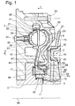
- Fig. 1 shows a hydrodynamic retarder.
- Gear housing rotatable retarder 1 is provided, which is also a rotatable support member 3 radially surrounds.
- the support member 3 is, with interposition a radial bearing 11, also enclosed, of one Clutch hub 5 of a coupling unit 7, which via a coupling housing.
- 9 has and in a manner not shown with a transmission input shaft, also not shown in a rotationally fixed connection. Because of this connection, the Coupling unit 7 and thus the clutch housing 9 at a rotational movement of the Transmission input shaft part.
- the rotor blade wheel 25 acts with a second paddle wheel in the form of a Statorschaufelrades 27th the retarder together, which also has a base body 29, which as Stator shell 31 is effective and for receiving a blading 33 with blades 35 serves.
- On the stator shell 31 are facing away from the rotor blade wheel 25 at its Side over the circumference threaded sleeves 39 provided in each of a fastening element 37 can be introduced, wherein by the fastening elements 37 in conjunction with the threaded sleeves 39, the Statorschaufelrad 27 am Retarder 1 is attached.
- the rotor blade wheel 25 forms a hydrodynamic together with the stator blade wheel 27 Circle 41, which is at least partially filled with viscous medium.
- the degree of filling of the hydrodynamic circuit 41 can be achieved by means of a fluid supply 43 are increased, while via a fluid outlet 45 viscous medium from the hydrodynamic circuit 41 can be withdrawn. In a known way can over the degree of filling of the hydrodynamic circuit 41 whose torque transferability and thus the braking effect triggered by the retarder can be adjusted.
- the fluid supply 43 thus serves in connection with the fluid outlet 45 for Regulation of the retarder.
- the sealing flange 51 has a substantially in the radially inner region of the Rotor blade wheel 25 trimmed, axially extending receiving projection 55th on which an annular spring seal 57 is provided. This engages with a first leg 59 a provided on the receiving projection 55 radial nose 63 and engages with a second leg 61, the radial opposite side of the receiving projection 55.
- annular spring seal 57 loaded with a bottom surface 65, the clutch hub 5.
- a sealing ring 67 is inserted, preferably as well as the groove 69 is of rectangular cross-section.
- the sealing ring 67 is preferably made of gray cast iron, but is alternatively also made of an elastomeric Material can be produced.
- the sealing ring is formed in the clutch hub 5, assigned to substantially radially extending lubrication hole 71.
- the retarder is centered with respect to an axis 90.
- This axis can also be seen in FIGS. 2 and 3, wherein in particular FIG. 2 for illustrating the blading 33 in the base body 29 of the stator blade wheel 27 serves. Since the rotor blade wheel 25 with respect to the attachment and arrangement its blading 21 in the base body 19 is formed identically as the Statorschaufelrad 27, the following description should refer to the Statorschaufelrad 27 restrict.
- FIG. 4 shows a blade 35 with two circumferentially juxtaposed blades 35 formed ring segment of Statorschaufelrads shown in Fig. 2 in its entirety 27.
- this has, as clearly shown in Fig. 5, a plurality of receptacles 73, 75, 77, of which a radially outer receptacle 73 and a radially inner receptacle 75 with respect to an inner body wall 30 with a predominant Extend component in the radial direction, which is why these two shots 73, 75 are referred to below as radial recordings.
- the radial receptacle 73 extends in this case, starting from the inner base body wall 30, radially outside, the radial receptacle 75, however, radially inward.
- the further receptacle 77 is provided which, starting from the inner body wall 30 extends with a predominant component in the axial direction, why this recording 77 is referred to below as Axialtext. These is, preferably by means of plastic deformation, deeply worked into the main body 29 and radially outwardly as well as radially inwardly bounded by the same.
- Axialtext 77 on its side facing away from the blade chamber 34 side bounded by a bottom 104 of the base body 29, here a closed Page 102 while facing the other wheel, axial opposite side is formed as an open side 86.
- the radial receivers 73, 75 have a significantly lower penetration depth into the base body 29, and are through this also only in the radial direction and in the direction of its closed side 102 limited.
- On the side of the open end 86 of the main body 29 is against both the radial receptacle 73 and the radial receptacle 75 each open, and penetrates thereby one of the open side 86 associated axial edge region 88. This is shown in dashed line in Fig. 5.
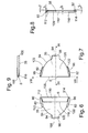
- Fig. 6 shows a blade 35 as a detail and in the position in which they in the main body 29 shown in Fig. 5 is to be used.
- the shovel 35 has paddles 80, 82 extending from a body-side Blade edge 94, with a predominant component in the radial direction extend and therefore hereinafter referred to as radial vanes.
- a further blade flap 84 is provided approximately in the radial blade center, which, starting from the main body side blade edge 94 with a predominant Axial component extends and therefore referred to as Axialschaufellappen 84 is.
- the Axialschaufellappen 84 is at its from the base body side Blade edge 94 pioneering free end 98 provided with an impression 106 which can also be seen in Fig. 9.
- the axial side of the blade 35 which is opposite the axial blade 84, serves as a fluid-inlet-side edge 108, on which an embossment 110 (see also FIG. Radially outside the embossment 110 there is a first support region 112, while a second support region 114 is provided radially within the embossment 110.
- These support regions 112, 114 are respectively provided radially adjacent to the radial vane lobes 80, 82 and, as shown in FIG. 8, extend substantially over the cross section of the vane 35.
- the imprint 110 radially in between, on the other hand, progressively reduces the vane cross section from a blade-inner edge 118 (FIG.
- b 1 indicates the cross section at the fluid inlet-side edge 108 and the cross-section in the support region 112 at the location with b 2 .
- the aim of these measures is that in the usual inclination of the blades 35 in the base body 29, as can be seen in Fig. 11, the shear surface S due to the embossing 110 and thus increases the torque transmission capacity relative to the other paddle wheel is increased while simultaneously due to the Supporting portions 112, 114 (Fig. 6, 8) has the blade 35 in the transverse direction due to the higher cross section of the desired stability.
- FIG. 7 shows the blade 35 from its rear side, without the embossings 106 and 110 is formed.
- the blade 35 is inserted into the main body 29, if abutment ends 122 on the radial vane lobes 80, 82 the respectively associated Have reached stop edges 120 in the body.
- the Axialschaufellappen 84 has then penetrated into the Axialability 77 and comes with its free end 98 both on the bottom 104 of the Axialability 77 and, because of its Anoniagung 106, on one of the side walls 100 (see Fig. 11) for installation.
- brazing solder shown in Fig. 11 by puncturing is, in the remaining space 124 of the Axialability 77 penetrated and cured, a composite has emerged, which is characterized by high stability.
- the radial vane lobes 80, 82 are respectively aligned with the axis 90, while, as auxiliary lines h 3 and h 4 show, the vanes 35 are positioned in the base body 29 are that they would miss the axis 90 in extension. While the orientation of the blades 35 in the body 29 results from fluid dynamic conditions, should be excluded by alignment of the radial vanes 80, 82 on the axis 90, any imbalance. As shown in FIG. 10, the radial blade flap 82 emanating from the base-body-side blade edge 94 is ⁇ with its free end 96 opposite the actual blade by the angle .beta ..
- the radial receptacle 75 is formed at an angle ⁇ relative to the inner base body wall 30 of the base body 29, wherein, although the radial receptacle 75 is aligned to the axis 90, the angle ⁇ the angle ⁇ essentially corresponds.
- the radial receptacle 75 has a bottom 92 which is angularly adapted to the free end 96 of the radial blade flap 82 and thus can support it.
- the blades 35 along their fluid inlet side Edges 108 are each formed with a shield 116, said shield 116 toward the pressure side to the durability of the blade to increase.
- This shield is shown in Fig. 11 in particular on the right To recognize a shovel.
Landscapes
- Engineering & Computer Science (AREA)
- General Engineering & Computer Science (AREA)
- Mechanical Engineering (AREA)
- Braking Arrangements (AREA)
Abstract
Description
- Fig. 1
- Die obere Hälfte eines Längsschnittes durch einen hydrodynamischen Retarder mit einem Rotor- und einem Statorschaufelrad;
- Fig. 2
- eine Draufsicht auf das herausgezeichnete Statorschaufelrad gemäß der Blickrichtung II-II in Fig. 1;
- Fig. 3
- einen Schnitt durch das Statorschaufelrad gemäß der Schnittlinie III-III in Fig. 2;
- Fig. 4
- einen Schnitt durch das Statorschaufelrad gemäß der Schnittlinie IV-IV in Fig. 2;
- Fig. 5
- wie Fig. 4, aber gemäß der Schnittlinie V-V und somit ohne Schaufeln;
- Fig. 6
- eine der in Fig. 4 erkennbaren Schaufeln als Einzelheit;
- Fig. 7
- die Schaufel nach Fig. 6, von der Gegenseite aus gesehen;
- Fig. 8
- die Schaufel mit Blickrichtung VIII-VIII in Fig. 7;
- Fig. 9
- die Schaufel gemäß einer Schnittlinie IX-IX in Fig. 7;
- Fig. 10
- eine detaillierte Herauszeichnung des Eindringens eines Axialschaufellappens der Schaufel in eine Radialaufnahme des Grundkörpers in Schnittdarstellung;
- Fig. 11
- eine detaillierte Herauszeichnung des Eindringens von Axialschaufellappen der Schaufeln in eine jeweils zugeordnete Axialaufnahme des Grundkörpers in Schnittdarstellung.
- 1.
- Retarderträger
- 3.
- Stützelement
- 5.
- Kupplungsnabe
- 7.
- Kupplungseinheit
- 9.
- Kupplungsgehäuse
- 11.
- Radiallagerung
- 13.
- Verzahnung
- 15.
- Rotornabe
- 17.
- Axiallagerung
- 19.
- Grundkörper
- 20.
- Rotorschale
- 21.
- Beschaufelung
- 23.
- Schaufeln
- 25.
- Rotorschaufelrad
- 27.
- Statorschaufelrad
- 29.
- Grundkörper
- 30.
- innere Grundköperwand
- 31.
- Statorschale
- 33.
- Beschaufelung
- 34.
- Schaufelraum
- 35.
- Schaufeln
- 37.
- Befestigungselement
- 39.
- Gewindehülse
- 41.
- hydrodynamischer Kreis
- 43.
- Fliudzufuhr
- 45.
- Fluidauslass
- 47.
- Druckausgleich
- 49.
- Ausgleichsraum
- 51.
- Dichtflansch
- 53.
- Befestigungselemente
- 55.
- Aufnahmevorsprung
- 57.
- Ringfederdichtung
- 59,61
- Schenkel
- 63.
- Radialnase
- 65.
- Bodenfläche
- 67.
- Dichtring
- 69.
- Nutung
- 71.
- Schmierbohrung
- 73,75
- Radialaufnahmen
- 77.
- Axialaufnahme
- 80,82
- Radialschaufellappen
- 84.
- Axialschaufellappen
- 86.
- offene Seite
- 88.
- axialer Randbereich
- 90.
- Achse
- 92.
- Boden
- 94.
- grundkörperseitiger Schaufelrand
- 96.
- freies Ende
- 98.
- freies Ende
- 100.
- Seitenwände
- 102.
- geschlossene Seite
- 104
- Boden
- 106.
- Anprägung
- 108.
- fluideintrittsseitige Kante
- 110.
- Anprägung
- 112,114
- Stützbereiche
- 116.
- Schirmung
- 118.
- schaufelinnere Kante
- 120.
- Anschlagkanten
- 122.
- Axialenden
- 124.
- Freiraum
- 126.
- Schaufelfläche
Claims (12)
- Hydrodynamischer Retarder oder hydrodynamische Kupplung mit einem ersten Schaufelrad und einem zweiten Schaufelrad, die gemeinsam einen hydrodynamischen Kreis bilden und von denen jedes Schaufelrad aus jeweils einem Grundkörper und einer an diesem festen Beschaufelung mit einer Mehrzahl von Schaufeln besteht, die jeweils über Schaufellappen mit Aufnahmen des Grundkörpers in Eingriff bringbar sind, wobei mindestens ein Teil der Schaufellappen sowie der zugeordneten Aufnahmen gegenüber dem jeweiligen Trägerteil, also Schaufel oder Grundkörper, mit einer überwiegenden Komponente in Radialrichtung ausgerichtet und somit als Radialschaufellappen oder Radialaufnahmen wirksam sind, und/oder mindestens ein Teil der Schaufellappen sowie der zugeordneten Aufnahmen gegenüber dem jeweiligen Trägerteil mit einer überwiegenden Komponente in Axialrichtung ausgerichtet sind und somit als Axialschaufellappen oder Axialaufnahmen dienen,
dadurch gekennzeichnet, dass
wenigstens ein Teil der Radialaufnahmen (73, 75) in den axialen Randbereich (88) des Grundkörpers (19, 29) eines Schaufelrades (25, 27) an dessen dem Grundkörper (19, 29) des jeweils anderen Schaufelrades (25, 27) zugewandter offener Seite (86) zumindest eindringen. - Hydrodynamischer Retarder oder hydrodynamische Kupplung nach Anspruch 1,
dadurch gekennzeichnet, dass
wenigstens ein Teil der Radialaufnahmen (73, 75) den axialen Randbereich (88) des Grundkörpers (19, 29) axial vollständig durchdringen und an der offenen Seite (86) desselben münden. - Hydrodynamischer Retarder oder hydrodynamische Kupplung nach Anspruch 1 oder 2 mit einem Rotor- und einem Statorschaufelrad, die gegenüber einer gemeinsamen Achse zentriert sind
dadurch gekennzeichnet, dass
wenigstens ein Teil der Radialaufnahmen (73, 75) jeweils unter einem Winkel (α) auf die Achse (90) des jeweiligen Schaufelrades (25, 27) ausgerichtet ist. - Hydrodynamischer Retarder oder hydrodynamische Kupplung nach einem der Ansprüche 1 bis 3,
dadurch gekennzeichnet, dass
bei wenigstens einem Teil der Radialaufnahmen (73, 75) jeweils ein Boden (92) winkelmäßig auf ein gegenüber einem vom grundkörperseitigen Schaufelrand (94) der Schaufel (23, 35) abgewandten freien Ende (96) des zugeordneten Radialschaufellappens (80, 82) ausgerichtet ist. - Hydrodynamischer Retarder oder hydrodynamische Kupplung nach einem der Ansprüche 1 bis 4,
dadurch gekennzeichnet, dass
wenigstens ein Teil der Radialschaufellappen (80, 82) zumindest entlang eines Teils ihrer Radialerstreckung gegenüber einer Schaufelfläche (126) der Schaufel (23, 25) unter einem vorbestimmten Winkel (β) gegenüber dieser ausgerichtet ist. - Hydrodynamischer Retarder oder hydrodynamische Kupplung nach Anspruch 5,
dadurch gekennzeichnet, dass
sich der vorbestimmte Winkel (β) für die Radialschaufellappen (80, 82) aus deren Ausrichtung auf die Achse (90) der Schaufelräder (25, 27) und der Erstreckungsrichtung der Schaufeln (23, 35) im Grundkörper (19, 29) ergibt. - Hydrodynamischer Retarder oder hydrodynamische Kupplung nach einem der Ansprüche 1 bis 6 mit Schaufeln, die unter einem vorbestimmten Winkel gegenüber einer geschlossenen Seite des Grundkörpers eingesetzt sind,
dadurch gekennzeichnet, dass
die Axialschaufellappen (84) jeweils mit ihren vom grundkörperseitigen Schaufelrand (94) abgewandten freien Enden (98) unter dem vorbestimmten Winkel (γ) in die zugeordnete Axialaufnahme (77) eingreifen. - Hydrodynamischer Retarder oder hydrodynamische Kupplung nach Anspruch 7,
dadurch gekennzeichnet, dass
die Axialaufnahmen (77) jeweils Seitenwände (100) aufweisen, die im Wesentlichen senkrecht zur geschlossenen Seite (102) des Grundkörpers (19, 29) verlaufen und über einen Boden (104) miteinander verbunden sind, der im Wesentlichen parallel zur geschlossenen Seite (102) des Grundkörpers (19, 29) ausgerichtet ist, wobei der Boden (104) die Seitenwände (100) auf einem Abstand (A) zueinander hält, der den Querschnitt (L) des Axialschaufellappens (84) übersteigt. - Hydrodynamischer Retarder oder hydrodynamische Kupplung nach Anspruch 7 oder 8,
dadurch gekennzeichnet, dass
die Axialschaufellappen (84) jeweils an ihren vom grundkörperseitigen Schaufelrand (94) abgewandten freien Enden (98) mit Anprägungen (106) ausgebildet sind, die an zumindest einer Seitenwand (100) der Axialaufnahme (77) in Anlage kommen. - Hydrodynamischer Retarder oder hydrodynamische Kupplung nach einem der Ansprüche 1 bis 9,
dadurch gekennzeichnet, dass
die Schaufeln (23, 35) der Schaufelräder (25, 27) in Richtung zur Druckseite mit einer Schirmung (116) ausgebildet sind. - Hydrodynamischer Retarder oder hydrodynamische Kupplung nach einem der Ansprüche 1 bis 9,
dadurch gekennzeichnet, dass
die Schaufeln (23, 35) der Schaufelräder (25, 27) an einer fluideintrittsseitigen Kante (108) mit einer die Scherfläche (S) der Schaufeln (23, 35) vergrößernden Anprägung (110) versehen sind. - Hydrodynamischer Retarder oder hydrodynamische Kupplung nach Anspruch 10 oder 11,
dadurch gekennzeichnet, dass
die Anprägung (110) radial zwischen Stützbereichen (112, 114) der Schaufeln (23, 25) vorgesehen sind, wobei die Stützbereiche (112, 114) als Verbindungen zwischen den Schaufeln (23, 35) und dem Grundkörper (19, 29) vorgesehen sind.
Applications Claiming Priority (2)
| Application Number | Priority Date | Filing Date | Title |
|---|---|---|---|
| DE10343425 | 2003-09-19 | ||
| DE2003143425 DE10343425A1 (de) | 2003-09-19 | 2003-09-19 | Hydrodynamischer Retarder oder hydrodynamische Kupplung |
Publications (2)
| Publication Number | Publication Date |
|---|---|
| EP1517061A1 true EP1517061A1 (de) | 2005-03-23 |
| EP1517061B1 EP1517061B1 (de) | 2008-08-27 |
Family
ID=34177839
Family Applications (1)
| Application Number | Title | Priority Date | Filing Date |
|---|---|---|---|
| EP20040021271 Expired - Lifetime EP1517061B1 (de) | 2003-09-19 | 2004-09-08 | Hydrodynamischer Retarder oder hydrodynamische Kupplung |
Country Status (2)
| Country | Link |
|---|---|
| EP (1) | EP1517061B1 (de) |
| DE (2) | DE10343425A1 (de) |
Cited By (3)
| Publication number | Priority date | Publication date | Assignee | Title |
|---|---|---|---|---|
| CN102168728A (zh) * | 2011-02-28 | 2011-08-31 | 中国北方车辆研究所 | 一种用于液力减速器的挡片装置 |
| CN102725556A (zh) * | 2010-01-29 | 2012-10-10 | 沃依特专利有限责任公司 | 液力机械、特别是液力减速器 |
| CN113586630A (zh) * | 2021-08-02 | 2021-11-02 | 山东泰鑫汽车科技有限公司 | 一种增强液力缓速器上的后定涡轮 |
Families Citing this family (4)
| Publication number | Priority date | Publication date | Assignee | Title |
|---|---|---|---|---|
| DE102007025675A1 (de) | 2007-06-01 | 2008-12-18 | Zf Friedrichshafen Ag | Hydrodynamischer Retarder |
| DE102007025676A1 (de) | 2007-06-01 | 2008-12-04 | Zf Friedrichshafen Ag | Hydrodynamischer Retarder |
| DE102011080643A1 (de) | 2011-08-09 | 2013-02-14 | Zf Friedrichshafen Ag | Hydrodynamischer Retarder |
| DE102014206753B4 (de) | 2014-04-08 | 2023-08-10 | Voith Patent Gmbh | Hydrodynamische Maschine |
Citations (4)
| Publication number | Priority date | Publication date | Assignee | Title |
|---|---|---|---|---|
| US2779292A (en) * | 1948-12-31 | 1957-01-29 | Borg Warner | Hydrodynamic coupling |
| US2785636A (en) * | 1953-12-28 | 1957-03-19 | Gen Motors Corp | Fluid coupling |
| DE4319469A1 (de) * | 1992-06-12 | 1993-12-16 | Nissan Motor | Schaufelrad und Gerät zu dessen Herstellung |
| DE10028229A1 (de) * | 1999-07-17 | 2001-01-25 | Mannesmann Sachs Ag | Schaufelrad für eine hydrodynamische Koppeleinrichtung |
-
2003
- 2003-09-19 DE DE2003143425 patent/DE10343425A1/de not_active Withdrawn
-
2004
- 2004-09-08 EP EP20040021271 patent/EP1517061B1/de not_active Expired - Lifetime
- 2004-09-08 DE DE200450007941 patent/DE502004007941D1/de not_active Expired - Lifetime
Patent Citations (4)
| Publication number | Priority date | Publication date | Assignee | Title |
|---|---|---|---|---|
| US2779292A (en) * | 1948-12-31 | 1957-01-29 | Borg Warner | Hydrodynamic coupling |
| US2785636A (en) * | 1953-12-28 | 1957-03-19 | Gen Motors Corp | Fluid coupling |
| DE4319469A1 (de) * | 1992-06-12 | 1993-12-16 | Nissan Motor | Schaufelrad und Gerät zu dessen Herstellung |
| DE10028229A1 (de) * | 1999-07-17 | 2001-01-25 | Mannesmann Sachs Ag | Schaufelrad für eine hydrodynamische Koppeleinrichtung |
Cited By (5)
| Publication number | Priority date | Publication date | Assignee | Title |
|---|---|---|---|---|
| CN102725556A (zh) * | 2010-01-29 | 2012-10-10 | 沃依特专利有限责任公司 | 液力机械、特别是液力减速器 |
| CN102725556B (zh) * | 2010-01-29 | 2015-07-08 | 福伊特专利有限公司 | 液力机械、特别是液力减速器 |
| CN102168728A (zh) * | 2011-02-28 | 2011-08-31 | 中国北方车辆研究所 | 一种用于液力减速器的挡片装置 |
| CN102168728B (zh) * | 2011-02-28 | 2013-05-01 | 中国北方车辆研究所 | 一种用于液力减速器的挡片装置 |
| CN113586630A (zh) * | 2021-08-02 | 2021-11-02 | 山东泰鑫汽车科技有限公司 | 一种增强液力缓速器上的后定涡轮 |
Also Published As
| Publication number | Publication date |
|---|---|
| DE10343425A1 (de) | 2005-04-14 |
| EP1517061B1 (de) | 2008-08-27 |
| DE502004007941D1 (de) | 2008-10-09 |
Similar Documents
| Publication | Publication Date | Title |
|---|---|---|
| EP1649197B1 (de) | Planetenträger für getriebe | |
| DE102009002481B4 (de) | Antriebssystem mit Drehmomentübertragungsanordnung und hydrodynamische Kopplungsanordnung | |
| DE60026062T2 (de) | Freilaufkupplungseinrichtung | |
| DE19981455B4 (de) | Hydrodynamischer Momentwandler, insbesondere für Kraftfahrzeuge | |
| DE3206068A1 (de) | Kupplungsscheibe | |
| DE10192763B3 (de) | Hydrodynamischer Momentwandler, insbesondere für Kraftfahrzeuge, mit verbesserten Mitteln zur Verbindung des Kolbens mit dem Deckel | |
| DE10317634B4 (de) | Drehmomentwandler | |
| EP1517061B1 (de) | Hydrodynamischer Retarder oder hydrodynamische Kupplung | |
| DE19880999B4 (de) | Hydrodynamischer Momentwandler mit verriegelbarer Kupplung für Kraftfahrzeuge | |
| DE102015102141B4 (de) | Transmitter für ein Schaltgetriebe für ein Kraftfahrzeug, Baugruppe mit Transmitter, Getriebewelle und Gangrad sowie Getriebe | |
| DE3517499C2 (de) | ||
| DE102008026428A1 (de) | Drehmomentwandler mit Schaufeln ohne Schweissnaht | |
| DE10011204B4 (de) | Hydrodynamische Kopplungseinrichtung | |
| DE19780552B4 (de) | Hydrodynamischer Momentwandler, insbesondere für Kraftfahrzeuge | |
| EP3959115B1 (de) | Längenverstellbare lenkwelle für ein kraftfahrzeug und profilhülse für eine lenkwelle | |
| EP1208313B1 (de) | Synchronkörper aus einem formteil aus blech | |
| EP1035349B1 (de) | Gummilager mit Axialanschlägen und Verfahren zur Herstellung eines Gummilagers mit integrierten Axialanschlägen | |
| EP3884183A1 (de) | Differentialgetriebe für ein kraftfahrzeug | |
| DE102011087076A1 (de) | Planetenradträger | |
| DE10213950B4 (de) | Hydrodynamische Kupplung, insbesondere Drehmomentwandler | |
| DE10257349A1 (de) | Hydrodynamischer Drehmomentwandler | |
| WO2019007901A1 (de) | Differentialgetriebegehäuse und differentialgetriebe | |
| DE10035264A1 (de) | Hydrodynamische Kopplungseinrichtung | |
| DE10213616B4 (de) | Hydrodynamische Kopplungseinrichtung | |
| DE102011076277A1 (de) | Planetenradträger |
Legal Events
| Date | Code | Title | Description |
|---|---|---|---|
| PUAI | Public reference made under article 153(3) epc to a published international application that has entered the european phase |
Free format text: ORIGINAL CODE: 0009012 |
|
| 17P | Request for examination filed |
Effective date: 20050114 |
|
| AK | Designated contracting states |
Kind code of ref document: A1 Designated state(s): AT BE BG CH CY CZ DE DK EE ES FI FR GB GR HU IE IT LI LU MC NL PL PT RO SE SI SK TR |
|
| AX | Request for extension of the european patent |
Extension state: AL HR LT LV MK |
|
| AKX | Designation fees paid |
Designated state(s): DE FR GB |
|
| 17Q | First examination report despatched |
Effective date: 20070416 |
|
| GRAP | Despatch of communication of intention to grant a patent |
Free format text: ORIGINAL CODE: EPIDOSNIGR1 |
|
| GRAS | Grant fee paid |
Free format text: ORIGINAL CODE: EPIDOSNIGR3 |
|
| GRAA | (expected) grant |
Free format text: ORIGINAL CODE: 0009210 |
|
| AK | Designated contracting states |
Kind code of ref document: B1 Designated state(s): DE FR GB |
|
| REG | Reference to a national code |
Ref country code: GB Ref legal event code: FG4D Free format text: NOT ENGLISH |
|
| REF | Corresponds to: |
Ref document number: 502004007941 Country of ref document: DE Date of ref document: 20081009 Kind code of ref document: P |
|
| PLBE | No opposition filed within time limit |
Free format text: ORIGINAL CODE: 0009261 |
|
| STAA | Information on the status of an ep patent application or granted ep patent |
Free format text: STATUS: NO OPPOSITION FILED WITHIN TIME LIMIT |
|
| 26N | No opposition filed |
Effective date: 20090528 |
|
| PGFP | Annual fee paid to national office [announced via postgrant information from national office to epo] |
Ref country code: GB Payment date: 20090902 Year of fee payment: 6 |
|
| GBPC | Gb: european patent ceased through non-payment of renewal fee |
Effective date: 20100908 |
|
| PG25 | Lapsed in a contracting state [announced via postgrant information from national office to epo] |
Ref country code: GB Free format text: LAPSE BECAUSE OF NON-PAYMENT OF DUE FEES Effective date: 20100908 |
|
| PGFP | Annual fee paid to national office [announced via postgrant information from national office to epo] |
Ref country code: FR Payment date: 20140906 Year of fee payment: 11 |
|
| REG | Reference to a national code |
Ref country code: FR Ref legal event code: ST Effective date: 20160531 |
|
| PG25 | Lapsed in a contracting state [announced via postgrant information from national office to epo] |
Ref country code: FR Free format text: LAPSE BECAUSE OF NON-PAYMENT OF DUE FEES Effective date: 20150930 |
|
| PGFP | Annual fee paid to national office [announced via postgrant information from national office to epo] |
Ref country code: DE Payment date: 20160831 Year of fee payment: 13 |
|
| REG | Reference to a national code |
Ref country code: DE Ref legal event code: R119 Ref document number: 502004007941 Country of ref document: DE |
|
| PG25 | Lapsed in a contracting state [announced via postgrant information from national office to epo] |
Ref country code: DE Free format text: LAPSE BECAUSE OF NON-PAYMENT OF DUE FEES Effective date: 20180404 |