EP1517043B1 - Package-type fluidic apparatus - Google Patents
Package-type fluidic apparatus Download PDFInfo
- Publication number
- EP1517043B1 EP1517043B1 EP04022200A EP04022200A EP1517043B1 EP 1517043 B1 EP1517043 B1 EP 1517043B1 EP 04022200 A EP04022200 A EP 04022200A EP 04022200 A EP04022200 A EP 04022200A EP 1517043 B1 EP1517043 B1 EP 1517043B1
- Authority
- EP
- European Patent Office
- Prior art keywords
- housings
- exhaust
- package
- chambers
- sucking
- Prior art date
- Legal status (The legal status is an assumption and is not a legal conclusion. Google has not performed a legal analysis and makes no representation as to the accuracy of the status listed.)
- Expired - Lifetime
Links
- 239000012530 fluid Substances 0.000 claims description 11
- 238000007689 inspection Methods 0.000 claims description 6
- 238000012423 maintenance Methods 0.000 claims description 5
- 238000001816 cooling Methods 0.000 claims 1
- 230000007423 decrease Effects 0.000 description 8
- 230000006835 compression Effects 0.000 description 4
- 238000007906 compression Methods 0.000 description 4
- 230000002411 adverse Effects 0.000 description 1
- 239000000498 cooling water Substances 0.000 description 1
- 230000006837 decompression Effects 0.000 description 1
- 230000000694 effects Effects 0.000 description 1
- 238000009434 installation Methods 0.000 description 1
- 238000012986 modification Methods 0.000 description 1
- 230000004048 modification Effects 0.000 description 1
- 230000001131 transforming effect Effects 0.000 description 1
Images



Classifications
-
- F—MECHANICAL ENGINEERING; LIGHTING; HEATING; WEAPONS; BLASTING
- F04—POSITIVE - DISPLACEMENT MACHINES FOR LIQUIDS; PUMPS FOR LIQUIDS OR ELASTIC FLUIDS
- F04B—POSITIVE-DISPLACEMENT MACHINES FOR LIQUIDS; PUMPS
- F04B23/00—Pumping installations or systems
- F04B23/04—Combinations of two or more pumps
-
- F—MECHANICAL ENGINEERING; LIGHTING; HEATING; WEAPONS; BLASTING
- F01—MACHINES OR ENGINES IN GENERAL; ENGINE PLANTS IN GENERAL; STEAM ENGINES
- F01C—ROTARY-PISTON OR OSCILLATING-PISTON MACHINES OR ENGINES
- F01C21/00—Component parts, details or accessories not provided for in groups F01C1/00 - F01C20/00
- F01C21/007—General arrangements of parts; Frames and supporting elements
-
- F—MECHANICAL ENGINEERING; LIGHTING; HEATING; WEAPONS; BLASTING
- F04—POSITIVE - DISPLACEMENT MACHINES FOR LIQUIDS; PUMPS FOR LIQUIDS OR ELASTIC FLUIDS
- F04C—ROTARY-PISTON, OR OSCILLATING-PISTON, POSITIVE-DISPLACEMENT MACHINES FOR LIQUIDS; ROTARY-PISTON, OR OSCILLATING-PISTON, POSITIVE-DISPLACEMENT PUMPS
- F04C23/00—Combinations of two or more pumps, each being of rotary-piston or oscillating-piston type, specially adapted for elastic fluids; Pumping installations specially adapted for elastic fluids; Multi-stage pumps specially adapted for elastic fluids
-
- F—MECHANICAL ENGINEERING; LIGHTING; HEATING; WEAPONS; BLASTING
- F04—POSITIVE - DISPLACEMENT MACHINES FOR LIQUIDS; PUMPS FOR LIQUIDS OR ELASTIC FLUIDS
- F04C—ROTARY-PISTON, OR OSCILLATING-PISTON, POSITIVE-DISPLACEMENT MACHINES FOR LIQUIDS; ROTARY-PISTON, OR OSCILLATING-PISTON, POSITIVE-DISPLACEMENT PUMPS
- F04C23/00—Combinations of two or more pumps, each being of rotary-piston or oscillating-piston type, specially adapted for elastic fluids; Pumping installations specially adapted for elastic fluids; Multi-stage pumps specially adapted for elastic fluids
- F04C23/001—Combinations of two or more pumps, each being of rotary-piston or oscillating-piston type, specially adapted for elastic fluids; Pumping installations specially adapted for elastic fluids; Multi-stage pumps specially adapted for elastic fluids of similar working principle
-
- F—MECHANICAL ENGINEERING; LIGHTING; HEATING; WEAPONS; BLASTING
- F04—POSITIVE - DISPLACEMENT MACHINES FOR LIQUIDS; PUMPS FOR LIQUIDS OR ELASTIC FLUIDS
- F04C—ROTARY-PISTON, OR OSCILLATING-PISTON, POSITIVE-DISPLACEMENT MACHINES FOR LIQUIDS; ROTARY-PISTON, OR OSCILLATING-PISTON, POSITIVE-DISPLACEMENT PUMPS
- F04C29/00—Component parts, details or accessories of pumps or pumping installations, not provided for in groups F04C18/00 - F04C28/00
- F04C29/04—Heating; Cooling; Heat insulation
Definitions
- the present invention relates to a package-type fluidic apparatus in which a fluid machine such as a scroll compressor, a vacuum pump, an expander or a blower is connected to a drive source.
- a fluid machine such as a scroll compressor, a vacuum pump, an expander or a blower is connected to a drive source.
- a single high-output compressor is included within the package, or a plurality of low-output compressors are piled up to form a high-output compressor in a package.
- a plurality of compressors such as four are piled up to constitute a single package compressor, an example of such a single package compressor is given in XP 007900119.
- XP 007900119 When it operates with about 100 % of compression air, all the four compressors operate.
- One of the four stops with about 70 % of air consumption; two stop with less than 50 %; three stop with further decrease; and all stop with further decrease.
- electric power consumption is corresponding to the compression air consumption.
- Electric power consumption decreases compared with a single high-output compressor. If the compressor stops owing to any cause, capability for producing compression air becomes null immediately in the single high-output compressor to result in stop of all machines in which compression air is used, thereby increasing damage in the factory.
- a plurality of compressors even if one stops, it will avoid the risk that operation completely stops, as the others continue to operate.
- a plurality of compressors may preferably be employed.
- a compressor and its drive source form a set of subsidiary unit.
- a required area increases to unable its location.
- a plurality of subsidiary units are vertically piled.
- JP 02-049458 discloses a cooling water supply device wherein two stacked units are placed on the opposite sides of a common duct-shaped path for the exhaust air flow.
- One embodiment of this document shows independent air inlets placed on the respective sides of the housings.
- Two housings 2,2 each of which has four chambers 1 piled up are disposed with a space which is a sucking path 3.
- the housings 2,2 have the same shape and size, and the four chambers 1 have the same shape and size.
- the sucking path 3 is closed by a removable inspection door 5 between front walls 4,4 over the housings 2,2.
- the upper part of the sucking path 3 is closed by an operation-display plate 5b.
- the rear end of the sucking path 3 opens, and external air is taken in through the rear opening.
- the side ends of the operation-display plate 5b are mounted with screws to the opposing ends of the housings 2,2, and the operation-display plate 5b can be removed, if required.
- the inspection door 5 is removable by pushing down a slide latch 5a with a finger to open, so that sucking filters of fluid machines 8 in the housings 2,2 are inspected for maintenance.
- a motor 7 and the fluid machine 8 such as a compressor or a decompression device behind the motor 7 are connected to pulleys 9,10 and a belt 11 to form a fluid machine unit 12.
- a sucking hole 14 is formed through the inner side wall 13 to allow each of the housings 2,2 to communicate with the sucking path 3.
- an exhaust hole 16 is formed in a rear wall 15.
- a tall exhaust duct 17 is provided along the four exhaust holes 16 vertically arranged behind the housing 2.
- An electric exhaust fan 18 is provided in the top wall of the exhaust duct 17.
- the motor 7 and fluid machine 8 in the chamber 1 are cooled with external air, thereby avoiding overheat generated with continuous long-time operation and preventing damage to sliding parts.
- the motor 7 and fluid machine 8 in the chamber 1 can be inspected and maintained by removing a closing plate at the rear end of the sucking path 3 and then removing the inner side wall 13 facing the sucking path.
Landscapes
- Engineering & Computer Science (AREA)
- Mechanical Engineering (AREA)
- General Engineering & Computer Science (AREA)
- Compressors, Vaccum Pumps And Other Relevant Systems (AREA)
- Applications Or Details Of Rotary Compressors (AREA)
- Structures Of Non-Positive Displacement Pumps (AREA)
- Details Of Reciprocating Pumps (AREA)
Description
- The present invention relates to a package-type fluidic apparatus in which a fluid machine such as a scroll compressor, a vacuum pump, an expander or a blower is connected to a drive source.
- To reduce noise from a compressor and a drive source for driving it, they are often disposed within a package. A single high-output compressor is included within the package, or a plurality of low-output compressors are piled up to form a high-output compressor in a package.
- In particular, when a compressor is used in a factory, in view of the maximum air consumption, a single high-output compressor for producing it is used within a package.
- However, when air produced by a high-output compressor is used in a factory, the rate of operation is about 100 % all day long, while it decreases to less than 50 % depending on time in a day. According to a season in a year, compressed air consumption is variable and power source for driving a compressor cannot frequently be switched on and off when a high-output compressor is used.
- In a medium-sized or large machine in which a large air tank is difficult to put, as frequency of starting and stopping increases, it becomes likely to generate heat during starting of a motor, to decrease life of an electromagnetic switch and to cause mechanical problem of a compressor, and a motor starting current of a compressor becomes five to six times as that of rated operation to involve decrease in power source. In a large machine, voltage of power source decreases owing to the starting current and adverse effects to transforming and distribution installation so as not to enable on/off of the power source frequently.
- To solve such problems, for example, when output of the compressor is 15 kW, four compressors having output of 3.7 kW are included in a package. The compressors start with staggered time and the first, second, third and fourth compressors start in order to avoid the problem.
- Depending on air consumption, it is possible to determine the optimum number of operation. Specifically, a plurality of compressors such as four are piled up to constitute a single package compressor, an example of such a single package compressor is given in XP 007900119. When it operates with about 100 % of compression air, all the four compressors operate. One of the four stops with about 70 % of air consumption; two stop with less than 50 %; three stop with further decrease; and all stop with further decrease.
- Thus, electric power consumption is corresponding to the compression air consumption. Electric power consumption decreases compared with a single high-output compressor. If the compressor stops owing to any cause, capability for producing compression air becomes null immediately in the single high-output compressor to result in stop of all machines in which compression air is used, thereby increasing damage in the factory.
- On the contrary, in a plurality of compressors, even if one stops, it will avoid the risk that operation completely stops, as the others continue to operate. A plurality of compressors may preferably be employed.
- In a plurality of compressors, a compressor and its drive source form a set of subsidiary unit. However, when a plurality of the subsidiary units are disposed horizontally or stepwise, a required area increases to unable its location. To decrease the area, a plurality of subsidiary units are vertically piled.
- It is possible to pile them up, but is limited by height of a room and by how to transport. For maintenance of the taller compressor, a ladder must be used thereby increasing work of maintenance and involving danger.
- It is already known on the market the Powerex system of the SE series which is a package-type fluidic machine consisting of three stacked units of scroll compressors placed in a single housing. A vertical exhaust duct is also provided.
-
JP 02-049458 - In view of the disadvantages, it is an object of the invention to provide a package-type fluidic apparatus that can be maintained without ladders or without increase in area thereby facilitating inspection and maintenance of the fluid machine, for example, in case of a scroll compressor, enabling a fixed scroll to be disassembled, tip seals of fixed and orbiting scrolls to be replaced, a bearing to be greased up and a subsidiary unit to be exchanged easily.
- The above and other features and advantages of the invention will become more apparent from the following description with respect to an embodiment as shown in appended drawings wherein:
-
Fig. 1 is a front perspective view of a best-mode embodiment of a package-type fluidic apparatus according to the present invention; -
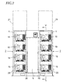
Fig. 2 is a front elevational view ofFig. 1 , removing right and left front closing plates of a housing, electric wires to a motor and conduits to the fluid machine; -
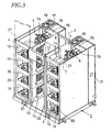
Fig. 3 is a front upper perspective view ofFig. 1 , removing a top plate, the closing plates and an inspection door; -
Fig. 4 is a top plan view in which the top plate is removed; and -
Fig. 5 is a vertical sectional view taken along the line V-V inFig. 2 . - Two
housings chambers 1 piled up are disposed with a space which is a suckingpath 3. Thehousings chambers 1 have the same shape and size. - The sucking
path 3 is closed by aremovable inspection door 5 betweenfront walls housings path 3 is closed by an operation-display plate 5b. The rear end of the suckingpath 3 opens, and external air is taken in through the rear opening. - The side ends of the operation-display plate 5b are mounted with screws to the opposing ends of the
housings inspection door 5 is removable by pushing down a slide latch 5a with a finger to open, so that sucking filters offluid machines 8 in thehousings - On a
bottom plate 6 of each of thechambers 1, amotor 7 and thefluid machine 8 such as a compressor or a decompression device behind themotor 7 are connected topulleys belt 11 to form afluid machine unit 12. - In the
chamber 1 of each of thehousings sucking hole 14 is formed through theinner side wall 13 to allow each of thehousings path 3. In thechamber 1 of each of thehousings exhaust hole 16 is formed in arear wall 15. Atall exhaust duct 17 is provided along the fourexhaust holes 16 vertically arranged behind thehousing 2. Anelectric exhaust fan 18 is provided in the top wall of theexhaust duct 17. - By driving the
exhaust fans fluid machine units 12 positioned depending on gas volume to be pressurized or depressurized, a place where the gas is utilized and reaching time to a predetermined pressure, external air flows into thechamber 1 through the suckingpath 3 and the sucking opening 14 and moves rearward. The air is discharged from theexhaust fan 18 through theexhaust duct 17. - Thus, the
motor 7 andfluid machine 8 in thechamber 1 are cooled with external air, thereby avoiding overheat generated with continuous long-time operation and preventing damage to sliding parts. - The
motor 7 andfluid machine 8 in thechamber 1 can be inspected and maintained by removing a closing plate at the rear end of the suckingpath 3 and then removing theinner side wall 13 facing the sucking path. - The foregoing merely relates to an embodiment of the invention. Various changes and modifications may be made by a person skilled in the art without departing from the scope of claims.
Claims (3)
- A package-type fluidic apparatus comprising two housings (2, 2) each comprising a plurality of chambers (1) piled up therein, an exhaust duct (17) being provided at a rear wall of each of the housings (2, 2), each of said chambers (1) having an exhaust hole (16) and a fluid-machine unit in which a fluid machine is connected to a drive source, the exhaust duct (17) being connected to the exhaust holes (16) of said chambers (1), and a sucking path (3) between the two housings (2, 2), characterized in that:each of said chambers (1) has a sucking hole (14) formed in an inner side wall, the sucking path (3) opening at a rear end between the housings (2, 2) and allowing lateral access to the fluid machines on either side for the purpose of maintenance and inspection, each of said exhaust ducts (17) having an exhaust fan (18) to allow air in each of said chambers (1) sucked via the sucking path (3) and the sucking hole (14) to be discharged to outside via the exhaust holes (16) and the exhaust ducts (17) thereby increasing cooling efficiency to the fluid-machine unit.
- A package-type fluidic apparatus as claimed in claim 1, wherein the two housings (2, 2) have substantially the same shape and size.
- A package-type fluidic apparatus as claimed in claim 1, wherein a front end of the sucking path (3) is closed by an operation display plate (5b) and a removable inspection door (5) between the housings (2, 2).
Applications Claiming Priority (2)
| Application Number | Priority Date | Filing Date | Title |
|---|---|---|---|
| JP2003330494 | 2003-09-22 | ||
| JP2003330494A JP3946678B2 (en) | 2003-09-22 | 2003-09-22 | Package type fluid machinery |
Publications (3)
| Publication Number | Publication Date |
|---|---|
| EP1517043A2 EP1517043A2 (en) | 2005-03-23 |
| EP1517043A3 EP1517043A3 (en) | 2006-05-03 |
| EP1517043B1 true EP1517043B1 (en) | 2008-11-26 |
Family
ID=34191432
Family Applications (1)
| Application Number | Title | Priority Date | Filing Date |
|---|---|---|---|
| EP04022200A Expired - Lifetime EP1517043B1 (en) | 2003-09-22 | 2004-09-17 | Package-type fluidic apparatus |
Country Status (6)
| Country | Link |
|---|---|
| US (1) | US20050063844A1 (en) |
| EP (1) | EP1517043B1 (en) |
| JP (1) | JP3946678B2 (en) |
| KR (1) | KR100584653B1 (en) |
| CN (1) | CN100371594C (en) |
| DE (1) | DE602004017945D1 (en) |
Cited By (1)
| Publication number | Priority date | Publication date | Assignee | Title |
|---|---|---|---|---|
| WO2023047095A1 (en) * | 2021-09-21 | 2023-03-30 | Scantech Offshore Limited | Air compressor |
Families Citing this family (18)
| Publication number | Priority date | Publication date | Assignee | Title |
|---|---|---|---|---|
| JP5119558B2 (en) * | 2005-10-03 | 2013-01-16 | オリオン機械株式会社 | Pneumatic equipment station and storage box for pneumatic equipment |
| JP5041849B2 (en) * | 2007-04-02 | 2012-10-03 | オリオン機械株式会社 | Exhaust temperature control system for pneumatic equipment station |
| JP4864798B2 (en) * | 2007-04-02 | 2012-02-01 | オリオン機械株式会社 | Shelf structure and pneumatic device storage box |
| CN101776060A (en) * | 2010-01-20 | 2010-07-14 | 常州亿晶光电科技有限公司 | Vacuum pump cooling device of automatic solar cell welding machine |
| JP5707280B2 (en) * | 2011-08-24 | 2015-04-22 | 株式会社日立産機システム | Package type compressor. |
| JP5899150B2 (en) | 2013-04-19 | 2016-04-06 | 株式会社日立産機システム | Package type fluid machinery |
| JP5728738B2 (en) * | 2014-01-08 | 2015-06-03 | オリオン機械株式会社 | Package type rotary pump unit |
| US10072673B2 (en) * | 2014-08-04 | 2018-09-11 | Powerex-Iwata Air Technology, Inc. | Compressor system |
| JP2016145557A (en) * | 2015-02-09 | 2016-08-12 | アネスト岩田株式会社 | Package type fluid machinery |
| JP6812343B2 (en) * | 2015-05-29 | 2021-01-13 | ナブテスコ株式会社 | Air compressor |
| JP6571422B2 (en) * | 2015-07-03 | 2019-09-04 | 株式会社神戸製鋼所 | Packaged air-cooled screw compressor |
| US10704552B2 (en) * | 2016-02-02 | 2020-07-07 | Powerex/Iwata Air Technology Inc. | Vacuum system |
| KR102283382B1 (en) * | 2017-06-26 | 2021-07-29 | 세메스 주식회사 | Vehicle maintenance lift |
| USD899463S1 (en) * | 2018-09-12 | 2020-10-20 | Sulzer Management Ag | Compressor |
| EP3851673B1 (en) * | 2018-09-13 | 2023-11-22 | Hitachi Industrial Equipment Systems Co., Ltd. | Package type fluid machine |
| JP1689745S (en) * | 2020-11-25 | 2021-07-12 | ||
| USD1081728S1 (en) * | 2022-03-30 | 2025-07-01 | Atlas Copco Airpower, Naamloze Vennootschap | Compressor |
| US20260201802A1 (en) * | 2025-01-16 | 2026-07-16 | Powerex-Iwata Air Technology Inc. | Multi-Vacuum Enclosure |
Family Cites Families (15)
| Publication number | Priority date | Publication date | Assignee | Title |
|---|---|---|---|---|
| FR1078545A (en) * | 1953-03-30 | 1954-11-18 | Fabrications Ind Pour Le Chauf | Fan device intended in particular for the air conditioning of premises and heating installation made using this device |
| US3242686A (en) * | 1964-10-20 | 1966-03-29 | Clark Equipment Co | Unitary machine room |
| US4007874A (en) * | 1975-08-14 | 1977-02-15 | Wilbert Laudner | Heating system |
| JPH0249458A (en) * | 1988-08-11 | 1990-02-19 | Hitachi Ltd | Cooling water supply device for lsi |
| JPH07113359B2 (en) * | 1989-08-19 | 1995-12-06 | トキコ株式会社 | Compressor |
| US5688169A (en) * | 1996-03-06 | 1997-11-18 | Lucent Technologies Inc. | Electrical equipment cabinet cooling |
| US6000623A (en) * | 1998-01-15 | 1999-12-14 | International Business Machines Corporation | System packaging for high performance computer applications |
| JP4077921B2 (en) | 1998-02-19 | 2008-04-23 | 株式会社日立製作所 | air compressor |
| JP2002291919A (en) * | 2001-03-30 | 2002-10-08 | Nec Corp | Fire protection for electronic devices |
| JP4014128B2 (en) | 2001-07-26 | 2007-11-28 | デンヨー株式会社 | air compressor |
| US6672955B2 (en) * | 2001-09-07 | 2004-01-06 | International Business Machines Corporation | Air flow management system for an internet data center |
| US6594148B1 (en) * | 2002-01-16 | 2003-07-15 | Cisco Technology, Inc. | Airflow system |
| KR100508140B1 (en) * | 2002-06-28 | 2005-08-10 | 가부시끼가이샤 히다치 세이사꾸쇼 | Packaged compressor |
| US6611428B1 (en) * | 2002-08-12 | 2003-08-26 | Motorola, Inc. | Cabinet for cooling electronic modules |
| US20060172685A1 (en) * | 2004-08-26 | 2006-08-03 | O'brien Paul | Internal environmental control system and uses thereof |
-
2003
- 2003-09-22 JP JP2003330494A patent/JP3946678B2/en not_active Expired - Fee Related
-
2004
- 2004-09-15 US US10/941,574 patent/US20050063844A1/en not_active Abandoned
- 2004-09-17 EP EP04022200A patent/EP1517043B1/en not_active Expired - Lifetime
- 2004-09-17 DE DE602004017945T patent/DE602004017945D1/en not_active Expired - Fee Related
- 2004-09-17 CN CNB2004100744963A patent/CN100371594C/en not_active Expired - Fee Related
- 2004-09-20 KR KR1020040075002A patent/KR100584653B1/en not_active Expired - Lifetime
Cited By (2)
| Publication number | Priority date | Publication date | Assignee | Title |
|---|---|---|---|---|
| WO2023047095A1 (en) * | 2021-09-21 | 2023-03-30 | Scantech Offshore Limited | Air compressor |
| AU2022349846B2 (en) * | 2021-09-21 | 2025-10-09 | Scantech Offshore Limited | Air compressor |
Also Published As
| Publication number | Publication date |
|---|---|
| EP1517043A3 (en) | 2006-05-03 |
| JP3946678B2 (en) | 2007-07-18 |
| JP2005098147A (en) | 2005-04-14 |
| DE602004017945D1 (en) | 2009-01-08 |
| CN100371594C (en) | 2008-02-27 |
| EP1517043A2 (en) | 2005-03-23 |
| CN1601082A (en) | 2005-03-30 |
| KR20050029691A (en) | 2005-03-28 |
| US20050063844A1 (en) | 2005-03-24 |
| KR100584653B1 (en) | 2006-05-30 |
Similar Documents
| Publication | Publication Date | Title |
|---|---|---|
| EP1517043A2 (en) | Package-type fluidic apparatus | |
| CN104110364B (en) | Box fluid machinery | |
| US11473582B2 (en) | Package-type compressor | |
| JP5205041B2 (en) | air compressor | |
| CN111727321A (en) | fluid machinery | |
| EP3258110A1 (en) | Package-type fluid machine | |
| KR100837143B1 (en) | Packaged compressor | |
| JP4255765B2 (en) | Package type compressor | |
| CN218062612U (en) | Gas Compression Components | |
| KR102592232B1 (en) | Air cooling system for fluidic machine | |
| JP4996142B2 (en) | Package type compressor | |
| JP5345719B2 (en) | Package type compressor with air dryer | |
| EP3851672A1 (en) | Package-type fluid machine | |
| JP2008111417A (en) | Air compressor | |
| JPWO2019077979A1 (en) | Compressor | |
| JP6986638B2 (en) | Package type fluid machine | |
| CN102052285A (en) | Pressurization compressor | |
| KR20230066824A (en) | Turbo blower package | |
| JP5668093B2 (en) | Booster compressor | |
| JPH06241501A (en) | Outdoor unit for air conditioner | |
| JP2006063858A (en) | Cooling means for scroll fluid machine |
Legal Events
| Date | Code | Title | Description |
|---|---|---|---|
| PUAI | Public reference made under article 153(3) epc to a published international application that has entered the european phase |
Free format text: ORIGINAL CODE: 0009012 |
|
| 17P | Request for examination filed |
Effective date: 20040917 |
|
| AK | Designated contracting states |
Kind code of ref document: A2 Designated state(s): AT BE BG CH CY CZ DE DK EE ES FI FR GB GR HU IE IT LI LU MC NL PL PT RO SE SI SK TR |
|
| AX | Request for extension of the european patent |
Extension state: AL HR LT LV MK |
|
| PUAL | Search report despatched |
Free format text: ORIGINAL CODE: 0009013 |
|
| AK | Designated contracting states |
Kind code of ref document: A3 Designated state(s): AT BE BG CH CY CZ DE DK EE ES FI FR GB GR HU IE IT LI LU MC NL PL PT RO SE SI SK TR |
|
| AX | Request for extension of the european patent |
Extension state: AL HR LT LV MK |
|
| AKX | Designation fees paid |
Designated state(s): BE DE FR IT |
|
| 17Q | First examination report despatched |
Effective date: 20070323 |
|
| GRAP | Despatch of communication of intention to grant a patent |
Free format text: ORIGINAL CODE: EPIDOSNIGR1 |
|
| GRAS | Grant fee paid |
Free format text: ORIGINAL CODE: EPIDOSNIGR3 |
|
| GRAA | (expected) grant |
Free format text: ORIGINAL CODE: 0009210 |
|
| AK | Designated contracting states |
Kind code of ref document: B1 Designated state(s): BE DE FR IT |
|
| REF | Corresponds to: |
Ref document number: 602004017945 Country of ref document: DE Date of ref document: 20090108 Kind code of ref document: P |
|
| PLBE | No opposition filed within time limit |
Free format text: ORIGINAL CODE: 0009261 |
|
| STAA | Information on the status of an ep patent application or granted ep patent |
Free format text: STATUS: NO OPPOSITION FILED WITHIN TIME LIMIT |
|
| 26N | No opposition filed |
Effective date: 20090827 |
|
| REG | Reference to a national code |
Ref country code: FR Ref legal event code: ST Effective date: 20100531 |
|
| PG25 | Lapsed in a contracting state [announced via postgrant information from national office to epo] |
Ref country code: FR Free format text: LAPSE BECAUSE OF NON-PAYMENT OF DUE FEES Effective date: 20090930 Ref country code: DE Free format text: LAPSE BECAUSE OF NON-PAYMENT OF DUE FEES Effective date: 20100401 |
|
| PG25 | Lapsed in a contracting state [announced via postgrant information from national office to epo] |
Ref country code: IT Free format text: LAPSE BECAUSE OF NON-PAYMENT OF DUE FEES Effective date: 20090917 |
|
| PGFP | Annual fee paid to national office [announced via postgrant information from national office to epo] |
Ref country code: BE Payment date: 20170921 Year of fee payment: 14 |
|
| REG | Reference to a national code |
Ref country code: BE Ref legal event code: MM Effective date: 20180930 |
|
| PG25 | Lapsed in a contracting state [announced via postgrant information from national office to epo] |
Ref country code: BE Free format text: LAPSE BECAUSE OF NON-PAYMENT OF DUE FEES Effective date: 20180930 |