EP1516833A1 - Conveyor device and method for transporting and/or sorting, especially food - Google Patents

Conveyor device and method for transporting and/or sorting, especially food Download PDF

Info

Publication number
EP1516833A1
EP1516833A1 EP03021263A EP03021263A EP1516833A1 EP 1516833 A1 EP1516833 A1 EP 1516833A1 EP 03021263 A EP03021263 A EP 03021263A EP 03021263 A EP03021263 A EP 03021263A EP 1516833 A1 EP1516833 A1 EP 1516833A1
Authority
EP
European Patent Office
Prior art keywords
conveying means
conveyor device
tensing
guide rollers
conveying
Prior art date
Legal status (The legal status is an assumption and is not a legal conclusion. Google has not performed a legal analysis and makes no representation as to the accuracy of the status listed.)
Withdrawn
Application number
EP03021263A
Other languages
German (de)
French (fr)
Inventor
Paolo Salvoni
Current Assignee (The listed assignees may be inaccurate. Google has not performed a legal analysis and makes no representation or warranty as to the accuracy of the list.)
GEA Food Solutions Italy SRL
Original Assignee
CFS Palazzolo SpA
Priority date (The priority date is an assumption and is not a legal conclusion. Google has not performed a legal analysis and makes no representation as to the accuracy of the date listed.)
Filing date
Publication date
Application filed by CFS Palazzolo SpA filed Critical CFS Palazzolo SpA
Priority to EP03021263A priority Critical patent/EP1516833A1/en
Priority to PCT/EP2004/010472 priority patent/WO2005028343A1/en
Publication of EP1516833A1 publication Critical patent/EP1516833A1/en
Withdrawn legal-status Critical Current

Links

Images

Classifications

    • BPERFORMING OPERATIONS; TRANSPORTING
    • B65CONVEYING; PACKING; STORING; HANDLING THIN OR FILAMENTARY MATERIAL
    • B65GTRANSPORT OR STORAGE DEVICES, e.g. CONVEYORS FOR LOADING OR TIPPING, SHOP CONVEYOR SYSTEMS OR PNEUMATIC TUBE CONVEYORS
    • B65G23/00Driving gear for endless conveyors; Belt- or chain-tensioning arrangements
    • B65G23/38Driving gear for endless conveyors; Belt- or chain-tensioning arrangements for effecting intermittent movement of belts or chains
    • BPERFORMING OPERATIONS; TRANSPORTING
    • B65CONVEYING; PACKING; STORING; HANDLING THIN OR FILAMENTARY MATERIAL
    • B65GTRANSPORT OR STORAGE DEVICES, e.g. CONVEYORS FOR LOADING OR TIPPING, SHOP CONVEYOR SYSTEMS OR PNEUMATIC TUBE CONVEYORS
    • B65G23/00Driving gear for endless conveyors; Belt- or chain-tensioning arrangements
    • B65G23/02Belt- or chain-engaging elements
    • B65G23/04Drums, rollers, or wheels
    • B65G23/12Arrangements of co-operating drums or rollers to augment tractive effort applied to the belts
    • BPERFORMING OPERATIONS; TRANSPORTING
    • B65CONVEYING; PACKING; STORING; HANDLING THIN OR FILAMENTARY MATERIAL
    • B65GTRANSPORT OR STORAGE DEVICES, e.g. CONVEYORS FOR LOADING OR TIPPING, SHOP CONVEYOR SYSTEMS OR PNEUMATIC TUBE CONVEYORS
    • B65G47/00Article or material-handling devices associated with conveyors; Methods employing such devices
    • B65G47/74Feeding, transfer, or discharging devices of particular kinds or types
    • B65G47/76Fixed or adjustable ploughs or transverse scrapers
    • B65G47/763Fixed ploughs or transverse scrapers

Definitions

  • the present invention relates to a conveyor device and a method for transporting and/or sorting.
  • a supplying station provides the goods to be transported to a receiving station where at the receiving station a further processing step is applied to the goods.
  • GB 896,425 discloses an apparatus delivering articles from a source of supply to a receiver whereas the apparatus comprises an endless conveying member from which articles are diverted onto another conveying member.
  • the conveying members at least partially act as storage means to store temporarily articles and thereby adapt the supply capacity of the source to the receiving capacity of the receiver.
  • the known apparatus is comparably complex and bulky, and therefore it requires considerable investments in terms of space and in terms of costs. Furthermore, the known apparatus works in an inflexible manner as it can not interact reliably with more than one supply source of articles when these supply sources provide the articles in a non-continuous manner.
  • a conveyor device particularly for transporting and/or sorting food or other transport goods, comprising a first part and a second part, the first part comprising a first conveying means and the second part comprising a second conveying means, the conveying means being arranged at least partially in parallel, the conveyor device further comprising a driving means, wherein the first part comprises tensing means, the tensing means being provided such that the first conveying means is driven while being tensed and the tensing means being provided such that the first conveying means is not driven while not being tensed.
  • the a.m. conveyor device is constructed in a very small, robust and simple way and nevertheless allows to transport and/or to sort food or other transport goods in an extremely flexible and versatile manner.
  • the first conveying means can be driven and can be stopped very easily and very rapidly only by tensing the first conveying means. Therefore, the conveyor device has a high throughput and more than one sources of supply can be connected to the device and be handled in a very flexible manner.
  • At least the first or the second conveying means is provided as a conveyor belt.
  • the conveying means is advantageous as the items or articles can be placed on a comparatively large surface without being damaged, e.g. through a contact with other parts of the device. Furthermore, the passing over of the articles or items from one of the conveying means to the other can be facilitated.
  • the conveying means it is obviously also possible to provide the conveying means as an endless string or, preferably, a multitude of endless and adjacent strings being moved in a common manner.
  • the tensing means comprise at least an actuator, especially a linear actuator and preferably a pneumatic actuator.
  • a linear actuator allows to provide the tensing means relatively easily and therefore render the device simple, compact and cost effective.
  • a pneumatically driven actuator is provided, but other kinds of actuators, e.g. electrical, mechanical, magnetic, thermal or being based on other principles, are also possible.
  • the first part of the device comprise a guiding means.
  • This allows to transfer the transported items or articles from one of the conveyor means, especially the first conveyor means, to another conveyor means, especially the second conveyor means.
  • Still further preferred is an embodiment of the invention with guiding means that traverses the first conveying means almost completely.
  • Such a guiding means is advantageous because it is simple and cost effective and provides a complete transfer of the transported articles or items in a very reliable manner.
  • the conveyor device comprises stop means. This allows the device to securely stop the first conveying means in the case where it is not tensed and even though the drive means are driving the second conveying means.
  • the conveyor device comprises first guide rollers, second guide rollers, third guide rollers and fourth guide rollers whereas the first part of the device comprises the first and the second guide rollers and whereas the second part of the device comprises the third and the fourth guide rollers and whereas at least either the first and third guide rollers or the second and fourth guide rollers rotate about a common axis.
  • the driving means commonly drive at least either the first and third guide rollers or the second and fourth guide rollers.
  • common driving means drive both conveyor means and therefore, the device can be built lightweight, cost effective and compactly.
  • the device transports the goods or the articles to or from a tray-sealer.
  • the device is especially part of a packaging machine ensemble with different working stations, one of which is a tray-sealing machine.
  • Such tray-sealing machines normally have a high throughput and therefore can handle the combined output of a plurality of other working stations, e.g. filling stations.
  • the device according to the invention allows therefore to combine the multitude of flows of articles supplied by, e.g., filling stations and to convey the articles or goods to the tray-sealing station.
  • Another subject matter of the present invention is a method for transporting and/or sorting, especially food or other transport goods, wherein a conveyor device comprises a first part and a second part, a driving means and tensing means whereas transported goods are transferred from the first part to the second part by means of guiding means when the tensing means are activated.
  • the first conveying means can be driven and stopped very easily and very rapidly and the items or articles can be moved or transferred from the first conveying means to the second very rapidly and reliably. Therefore, the forces applied to the goods when transferred from one conveying means to the other are rather small and the articles or goods are not damaged.
  • both parts 2, 3 comprise conveying means, i.e. the first part 2 comprises a first conveying means 20 and the second part 3 comprises a second conveying means 30.
  • the conveying means 20, 30 shown in Figure 1 are both of the belt-type, but other embodiments of the conveying means 20, 30 are possible, especially conveying means 20, 30 of the "string-type".
  • the direction of movement of the conveying means 20, 30 is denoted: both conveying means 20, 30 (when driven) are transporting goods or articles or items in the same direction.
  • the conveying means 20, 30 i.e.
  • the first and second parts 2, 3 of the device 1) are depicted as being arranged parallel and adjacent along their complete length.
  • the first conveying means 20 extend between a first guide roller 21 and a second guide roller 22 and the second conveying means 30 extend between a third guide roller 31 and a fourth guide roller 32.
  • the first and third guide rollers 21, 31 are provided rotatable about a first axis 11 and the second and fourth guide rollers 22, 32 are provided rotatable about a second axis 12.
  • at least one of the common axes 11, 12 are driven by a common driving means, especially an electrical driving means.
  • Other driving means such as mechanical, thermal, magnetic or being based on other principles, are also possible according to the invention.
  • the driving means are not depicted in the figures.
  • first and second parts 2, 3 such that they have different length and that they are arranged only partly adjacent (but still being parallel to each other). Furthermore, it is possible to provide only two of the rollers 21, 22, 31, 32 rotatable about a common axis 11, 12. Furthermore, it is also possible to provide two or more driving means to drive the rollers and therefore the conveying means 20, 30.
  • a side view of the conveyor device 1 according to the invention is schematically shown.
  • the first and second guide rollers 21, 22 of the first part 2 (or of the first conveying means 20) are provided such that the conveying means 20 are not tensed.
  • a tensing means comprising an actuator 24 and a tensing device 23, is arranged such that by an activation of the actuator from a "stop"-position (represented in Figure 2 by a continuous line) towards a "drive"-position (represented in Figure 2 by a dashed line), the first conveying means 20 is tensed such that enough friction is applied between the first conveying means 20 and the guide roller(s) 21, 22 driven by the driving means.
  • the tensing device 23 thereby transmits a sufficient force to the conveying means 20 in order to maintain enough friction in the conveying means 20.
  • This force is generally generated and maintained by the actuator 24.
  • the tensing device 23 comprises a roller which is driven by the conveying means 20 while in its "drive"-position.
  • different geometric arrangements of the tensing means 23, 24 relative to the first conveying means 20 are also possible, an example of which is depicted in Figure 3 .
  • FIG 3 a side view of an alternative embodiment of the conveyor device 1 according to the invention is schematically shown.
  • the tensing means 23, 24 are arranged differently, thereby providing another geometric arrangement of the tensing means 23, 24 relative to the first conveying means 20.
  • the force applied by the actuator 24 is directed in a direction almost parallel to the useful surface 2a of the first part 2.
  • the "drive"-position of the actuator 24 is represented by a dashed line and the "stop"-position is represented by a continuous line.
  • the alternative embodiment of the device 1 comprises a first auxiliary roller 25a and a second auxiliary roller 25b cooperating with the first and second guide rollers 21, 22.
  • the device 1 comprises stop means 27 that prevent the first conveying means 20 from moving in a situation where the tensing means 23, 24 are in their "stop"-position.
  • the stop means 27 are provided as jaws approaching one another in order to stop the first conveying means 20 and departing from one another in order to release the first conveying means 20 (so that the tensing means 23, 24 are allowed to take their "drive"-position).
  • FIG 4 a top view of the device 1 according to the invention is schematically shown.
  • the first part 2 and the second part 3 of the device 1 are shown arranged parallel and adjacent to one another.
  • the guide rollers 21, 22, 31, 32 and the directions 29, 39 of flow of the first and second conveying means 20, 30 are denoted in Figure 4 .
  • a guiding means 26 is shown which is arranged on the top of the useful surface of the first conveying means 20.
  • the guiding means 26 traverses the first conveying means 20 almost completely.
  • the guiding means 26 is provided at a height above the first conveying means 20 in order to "push" transported items or articles (not shown) from the first conveying means 20 towards the second conveying means 30.
  • the articles move along the guiding means 26 in a direction perpendicular to the direction of transport 29 of the first conveying means 20.
  • the guiding means 26 can be realised as a straight bar traversing the first conveying means almost completely.
  • the guiding means 26, according to the invention is provided as an easy to handle and easy to manufacture system.
  • the guiding means 26 can be provided pivotably mounted and the angle (not shown) that the guiding means 26 forms with the direction of transport 29 of the first conveying means 20 can therefore be provided variable.
  • an actuator (not shown) can be provided.
  • further tensing means could be provided at the second part 3 in order to tense or not to tense the second conveying means 30 thereby inducing the second conveying means 30 either to be driven or not, just in the same manner a with the first conveying means 20 and the tensing means 23, 24.

Abstract

The present invention relates to a conveyor device (1), particularly for transporting and/or sorting food or other transport goods, comprising a first part (2) and a second part (3), the first part (2) comprising a first conveying means (20) and the second part (3) comprising a second conveying means (30), the conveying means (20,30) being arranged at least partially in parallel, the conveyor device (1) further comprising a driving means, whereas the first part (2) comprises tensing means (23,24), the tensing means being provided such that the first conveying means (20) is driven while being tensed and the tensing means (23,24) being further provided such that the first conveying means (20) is not driven while not being tensed.

Description

The present invention relates to a conveyor device and a method for transporting and/or sorting.
It is known to transport goods, especially foodstuff, to and from different working stations by means of endless conveyors of the belt-type or of the string-type. Typically, a supplying station provides the goods to be transported to a receiving station where at the receiving station a further processing step is applied to the goods.
GB 896,425 discloses an apparatus delivering articles from a source of supply to a receiver whereas the apparatus comprises an endless conveying member from which articles are diverted onto another conveying member. The conveying members at least partially act as storage means to store temporarily articles and thereby adapt the supply capacity of the source to the receiving capacity of the receiver.
The known apparatus is comparably complex and bulky, and therefore it requires considerable investments in terms of space and in terms of costs. Furthermore, the known apparatus works in an inflexible manner as it can not interact reliably with more than one supply source of articles when these supply sources provide the articles in a non-continuous manner.
It was therefore the problem of the present invention to provide a conveyor device and a method for transporting and/or sorting that overcomes the above mentioned disadvantages.
The problem is solved with a conveyor device, particularly for transporting and/or sorting food or other transport goods, comprising a first part and a second part, the first part comprising a first conveying means and the second part comprising a second conveying means, the conveying means being arranged at least partially in parallel, the conveyor device further comprising a driving means, wherein the first part comprises tensing means, the tensing means being provided such that the first conveying means is driven while being tensed and the tensing means being provided such that the first conveying means is not driven while not being tensed.
It was totally surprising and could not have been expected by a person skilled in the art that the a.m. conveyor device is constructed in a very small, robust and simple way and nevertheless allows to transport and/or to sort food or other transport goods in an extremely flexible and versatile manner. According to the invention, the first conveying means can be driven and can be stopped very easily and very rapidly only by tensing the first conveying means. Therefore, the conveyor device has a high throughput and more than one sources of supply can be connected to the device and be handled in a very flexible manner.
Preferably, at least the first or the second conveying means is provided as a conveyor belt. This is advantageous as the items or articles can be placed on a comparatively large surface without being damaged, e.g. through a contact with other parts of the device. Furthermore, the passing over of the articles or items from one of the conveying means to the other can be facilitated. In an alternative embodiment of the invention, it is obviously also possible to provide the conveying means as an endless string or, preferably, a multitude of endless and adjacent strings being moved in a common manner.
In a preferred embodiment of the present invention, the tensing means comprise at least an actuator, especially a linear actuator and preferably a pneumatic actuator. A linear actuator allows to provide the tensing means relatively easily and therefore render the device simple, compact and cost effective. Especially, a pneumatically driven actuator is provided, but other kinds of actuators, e.g. electrical, mechanical, magnetic, thermal or being based on other principles, are also possible.
Preferably, the first part of the device comprise a guiding means. This allows to transfer the transported items or articles from one of the conveyor means, especially the first conveyor means, to another conveyor means, especially the second conveyor means. Still further preferred is an embodiment of the invention with guiding means that traverses the first conveying means almost completely. Such a guiding means is advantageous because it is simple and cost effective and provides a complete transfer of the transported articles or items in a very reliable manner.
Preferably, the conveyor device comprises stop means. This allows the device to securely stop the first conveying means in the case where it is not tensed and even though the drive means are driving the second conveying means.
In a preferred embodiment of the present invention, the conveyor device comprises first guide rollers, second guide rollers, third guide rollers and fourth guide rollers whereas the first part of the device comprises the first and the second guide rollers and whereas the second part of the device comprises the third and the fourth guide rollers and whereas at least either the first and third guide rollers or the second and fourth guide rollers rotate about a common axis. By providing a common axis for two of the guide rollers, the device can be built in a very compact manner and very cost effectively.
Preferably, the driving means commonly drive at least either the first and third guide rollers or the second and fourth guide rollers. By this provision, common driving means drive both conveyor means and therefore, the device can be built lightweight, cost effective and compactly.
In an especially preferred embodiment, the device transports the goods or the articles to or from a tray-sealer. In this embodiment, the device is especially part of a packaging machine ensemble with different working stations, one of which is a tray-sealing machine. Such tray-sealing machines normally have a high throughput and therefore can handle the combined output of a plurality of other working stations, e.g. filling stations. The device according to the invention allows therefore to combine the multitude of flows of articles supplied by, e.g., filling stations and to convey the articles or goods to the tray-sealing station.
Another subject matter of the present invention is a method for transporting and/or sorting, especially food or other transport goods, wherein a conveyor device comprises a first part and a second part, a driving means and tensing means whereas transported goods are transferred from the first part to the second part by means of guiding means when the tensing means are activated.
According to the invention, the first conveying means can be driven and stopped very easily and very rapidly and the items or articles can be moved or transferred from the first conveying means to the second very rapidly and reliably. Therefore, the forces applied to the goods when transferred from one conveying means to the other are rather small and the articles or goods are not damaged.
The conveyor device of the invention will be described in greater detail hereinafter in connection with the drawings which illustrate exemplary embodiments.
Figure 1
shows schematically a perspective view on a first part and a second part of a device according to the invention.
Figure 2
shows schematically a side view of the device according to the invention.
Figure 3
shows schematically a side view of an alternative embodiment of the device according to the invention.
Figure 4
shows schematically a top view of the device according to the invention.
In Figur 1, a perspective view on a first part 2 and a second part 3 of a conveyor device 1 according to the invention is schematically shown. Both parts 2, 3 comprise conveying means, i.e. the first part 2 comprises a first conveying means 20 and the second part 3 comprises a second conveying means 30. The conveying means 20, 30 shown in Figure 1 are both of the belt-type, but other embodiments of the conveying means 20, 30 are possible, especially conveying means 20, 30 of the "string-type". By arrows 29, 39, the direction of movement of the conveying means 20, 30 is denoted: both conveying means 20, 30 (when driven) are transporting goods or articles or items in the same direction. The conveying means 20, 30 (i.e. the first and second parts 2, 3 of the device 1) are depicted as being arranged parallel and adjacent along their complete length. The first conveying means 20 extend between a first guide roller 21 and a second guide roller 22 and the second conveying means 30 extend between a third guide roller 31 and a fourth guide roller 32. Thereby, the first and third guide rollers 21, 31 are provided rotatable about a first axis 11 and the second and fourth guide rollers 22, 32 are provided rotatable about a second axis 12. According to the invention, at least one of the common axes 11, 12 are driven by a common driving means, especially an electrical driving means. Other driving means, such as mechanical, thermal, magnetic or being based on other principles, are also possible according to the invention. The driving means are not depicted in the figures.
However, it is possible to provide the first and second parts 2, 3 such that they have different length and that they are arranged only partly adjacent (but still being parallel to each other). Furthermore, it is possible to provide only two of the rollers 21, 22, 31, 32 rotatable about a common axis 11, 12. Furthermore, it is also possible to provide two or more driving means to drive the rollers and therefore the conveying means 20, 30.
In Figure 2, a side view of the conveyor device 1 according to the invention is schematically shown. The first and second guide rollers 21, 22 of the first part 2 (or of the first conveying means 20) are provided such that the conveying means 20 are not tensed. According to the invention, a tensing means, comprising an actuator 24 and a tensing device 23, is arranged such that by an activation of the actuator from a "stop"-position (represented in Figure 2 by a continuous line) towards a "drive"-position (represented in Figure 2 by a dashed line), the first conveying means 20 is tensed such that enough friction is applied between the first conveying means 20 and the guide roller(s) 21, 22 driven by the driving means. The tensing device 23 thereby transmits a sufficient force to the conveying means 20 in order to maintain enough friction in the conveying means 20. This force is generally generated and maintained by the actuator 24. Preferably, the tensing device 23 comprises a roller which is driven by the conveying means 20 while in its "drive"-position. According to the invention, different geometric arrangements of the tensing means 23, 24 relative to the first conveying means 20 are also possible, an example of which is depicted in Figure 3.
In Figure 3, a side view of an alternative embodiment of the conveyor device 1 according to the invention is schematically shown. In the alternative embodiment of the device 1, the tensing means 23, 24 are arranged differently, thereby providing another geometric arrangement of the tensing means 23, 24 relative to the first conveying means 20. The force applied by the actuator 24 is directed in a direction almost parallel to the useful surface 2a of the first part 2. Again the "drive"-position of the actuator 24 is represented by a dashed line and the "stop"-position is represented by a continuous line. Furthermore, the alternative embodiment of the device 1 comprises a first auxiliary roller 25a and a second auxiliary roller 25b cooperating with the first and second guide rollers 21, 22.
In a preferred embodiment of the invention, the device 1 comprises stop means 27 that prevent the first conveying means 20 from moving in a situation where the tensing means 23, 24 are in their "stop"-position. For example, the stop means 27 are provided as jaws approaching one another in order to stop the first conveying means 20 and departing from one another in order to release the first conveying means 20 (so that the tensing means 23, 24 are allowed to take their "drive"-position).
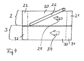
In Figure 4, a top view of the device 1 according to the invention is schematically shown. Again, the first part 2 and the second part 3 of the device 1 are shown arranged parallel and adjacent to one another. Furthermore, the guide rollers 21, 22, 31, 32 and the directions 29, 39 of flow of the first and second conveying means 20, 30 are denoted in Figure 4. Besides, a guiding means 26 is shown which is arranged on the top of the useful surface of the first conveying means 20. The guiding means 26 traverses the first conveying means 20 almost completely. The guiding means 26 is provided at a height above the first conveying means 20 in order to "push" transported items or articles (not shown) from the first conveying means 20 towards the second conveying means 30. Relatively to the (moving) first conveying means 20, the articles move along the guiding means 26 in a direction perpendicular to the direction of transport 29 of the first conveying means 20. The guiding means 26 can be realised as a straight bar traversing the first conveying means almost completely. Thereby, the guiding means 26, according to the invention, is provided as an easy to handle and easy to manufacture system. For example, the guiding means 26 can be provided pivotably mounted and the angle (not shown) that the guiding means 26 forms with the direction of transport 29 of the first conveying means 20 can therefore be provided variable. To pivot the guiding means 26, an actuator (not shown) can be provided. By this, an easy system of transfer of articles from one of the conveying means to the other of the conveying means is possible.
According to alternative embodiments (not shown) of the invention, further tensing means (not shown) could be provided at the second part 3 in order to tense or not to tense the second conveying means 30 thereby inducing the second conveying means 30 either to be driven or not, just in the same manner a with the first conveying means 20 and the tensing means 23, 24.
Reference numbers
1
device
2
first part
2a
useful surface of the first part
3
second part
11
first axis
12
second axis
20
first conveying means
21
first guide roller
22
second guide roller
23, 24
tensing means
25a
first auxiliary roller
25b
second auxiliary roller
26
guiding means
27
stop means
29
direction of movement of the first conveying means
30
second conveying means
31
third guide roller
32
fourth guide roller
39
direction of movement of the first conveying means

Claims (9)

  1. Conveyor device (1), particularly for transporting and/or sorting food or other transport goods, comprising a first part (2) and a second part (3), the first part (2) comprising a first conveying means (20) and the second part (3) comprising a second conveying means (30), the conveying means (20, 30) being arranged at least partially in parallel, the conveyor device (1) further comprising a driving means, characterised in that the first part (2) comprises tensing means (23, 24), the tensing means (23, 24) being provided such that the first conveying means (20) is driven while being tensed and the tensing means (23, 24) being further provided such that the first conveying means (20) is not driven while not being tensed.
  2. Conveyor device (1) according to claim 1, characterised in that at least the first or the second conveying means (20, 30) is provided as a conveyor belt.
  3. Conveyor device (1) according to any of the preceding claims, characterised in that the first tensing means (23, 24) comprise at least an actuator (24), especially a linear actuator and preferably a pneumatic actuator.
  4. Conveyor device (1) according to any of the preceding claims, characterised in that at least the first part (2) comprises a guiding means (26).
  5. Conveyor device (1) according to any of the preceding claims, characterised in that the guiding means (26) traverses the first conveying means (20) almost completely.
  6. Conveyor device (1) according to any of the preceding claims, characterised in that the conveyor device (1) comprises stop means (27).
  7. Conveyor device (1) according to any of the preceding claims, characterised in that the conveyor device (1) comprises first, second, third and fourth guide rollers (21, 22, 31, 32) whereas the first part (2) comprises the first and the second guide rollers (21, 22) and whereas the second part (3) comprises the third and the fourth guide rollers (31, 32) and whereas at least the first and the third guide rollers (21, 31) or the second and the fourth guide rollers (22, 32) rotate about a common axis (11, 12).
  8. Conveyor device (1) according to any of the preceding claims, characterised in that the driving means commonly drive at least either the first and the third guide rollers (21, 31) or the second and the fourth guide rollers (22, 32).
  9. Method for transporting and/or sorting, especially food or other transport goods, characterised in that a conveyor device (1) comprises a first part (2) and a second part (3), a driving means and tensing means (23, 24) whereas transported goods are transferred from the first part (2) to the second part (3) by means of guiding means (26) when the tensing means (23, 24) are activated.
EP03021263A 2003-09-19 2003-09-19 Conveyor device and method for transporting and/or sorting, especially food Withdrawn EP1516833A1 (en)

Priority Applications (2)

Application Number Priority Date Filing Date Title
EP03021263A EP1516833A1 (en) 2003-09-19 2003-09-19 Conveyor device and method for transporting and/or sorting, especially food
PCT/EP2004/010472 WO2005028343A1 (en) 2003-09-19 2004-09-17 Conveyor device and method for transporting and/or sorting, especially food

Applications Claiming Priority (1)

Application Number Priority Date Filing Date Title
EP03021263A EP1516833A1 (en) 2003-09-19 2003-09-19 Conveyor device and method for transporting and/or sorting, especially food

Publications (1)

Publication Number Publication Date
EP1516833A1 true EP1516833A1 (en) 2005-03-23

Family

ID=34178447

Family Applications (1)

Application Number Title Priority Date Filing Date
EP03021263A Withdrawn EP1516833A1 (en) 2003-09-19 2003-09-19 Conveyor device and method for transporting and/or sorting, especially food

Country Status (2)

Country Link
EP (1) EP1516833A1 (en)
WO (1) WO2005028343A1 (en)

Cited By (2)

* Cited by examiner, † Cited by third party
Publication number Priority date Publication date Assignee Title
DE102010017821A1 (en) 2010-04-20 2011-10-20 Bizerba Gmbh & Co Kg conveyor
DE102010015839A1 (en) 2010-04-20 2011-10-20 Bizerba Gmbh & Co. Kg Control procedure for a line unifier

Citations (3)

* Cited by examiner, † Cited by third party
Publication number Priority date Publication date Assignee Title
DE1107149B (en) * 1959-12-28 1961-05-18 Holstein & Kappert Maschf Device for transferring bottles and similar vessels from several conveyor tracks running parallel to one another onto one of these tracks
GB896425A (en) 1959-08-12 1962-05-16 Meyer Geo J Mfg Co Improvements in or relating to the delivery of articles from a supply to a receiver
DE4300271A1 (en) * 1993-01-08 1994-07-14 Klaus Ketterer Conveyor belt with cornering facility

Patent Citations (3)

* Cited by examiner, † Cited by third party
Publication number Priority date Publication date Assignee Title
GB896425A (en) 1959-08-12 1962-05-16 Meyer Geo J Mfg Co Improvements in or relating to the delivery of articles from a supply to a receiver
DE1107149B (en) * 1959-12-28 1961-05-18 Holstein & Kappert Maschf Device for transferring bottles and similar vessels from several conveyor tracks running parallel to one another onto one of these tracks
DE4300271A1 (en) * 1993-01-08 1994-07-14 Klaus Ketterer Conveyor belt with cornering facility

Cited By (4)

* Cited by examiner, † Cited by third party
Publication number Priority date Publication date Assignee Title
DE102010017821A1 (en) 2010-04-20 2011-10-20 Bizerba Gmbh & Co Kg conveyor
DE102010015839A1 (en) 2010-04-20 2011-10-20 Bizerba Gmbh & Co. Kg Control procedure for a line unifier
EP2380830A1 (en) 2010-04-20 2011-10-26 Bizerba GmbH & Co. KG Control method for a line connector
WO2011131312A1 (en) 2010-04-20 2011-10-27 Bizerba Gmbh & Co. Kg Conveyor device

Also Published As

Publication number Publication date
WO2005028343A1 (en) 2005-03-31

Similar Documents

Publication Publication Date Title
KR101335779B1 (en) Sorter belt conveyor
US3690435A (en) Article conveyor system
CA2437268C (en) Vertical diverter assembly
KR20180014679A (en) Conveyor Having Apparatus For Converting The Direction
KR20140064773A (en) Method and linear device for handling articles
KR20170036303A (en) Apparatus For Converting The Direction Of Conveyor
US20120055757A1 (en) Conveyor System
KR101380231B1 (en) Round belt conveyer apparatus
KR101968096B1 (en) Apparatus For Converting The Direction Of Conveyor
US6854586B1 (en) Unstable article conveying device with diverter having curved path
EP1516833A1 (en) Conveyor device and method for transporting and/or sorting, especially food
US6883659B2 (en) Conveyor transfer assembly
JP5797501B2 (en) Article sorting equipment
JP3160362B2 (en) Transfer device
JP3526619B2 (en) Article transfer device
JP4983314B2 (en) Conveyor equipment
JP5018562B2 (en) Transport equipment
JP5424449B2 (en) Article conveying device
JP5784952B2 (en) Article sorting equipment
JP4569202B2 (en) Sorting equipment
JP4984833B2 (en) Transport equipment
JPS59194918A (en) Conveyor device
JP4888892B2 (en) Sorting device
JP5843587B2 (en) Article sorting equipment
JPH0641934Y2 (en) Sorting device

Legal Events

Date Code Title Description
PUAI Public reference made under article 153(3) epc to a published international application that has entered the european phase

Free format text: ORIGINAL CODE: 0009012

AK Designated contracting states

Kind code of ref document: A1

Designated state(s): AT BE BG CH CY CZ DE DK EE ES FI FR GB GR HU IE IT LI LU MC NL PT RO SE SI SK TR

AX Request for extension of the european patent

Extension state: AL LT LV MK

17P Request for examination filed

Effective date: 20050923

AKX Designation fees paid

Designated state(s): AT BE BG CH CY CZ DE DK EE ES FI FR GB GR HU IE IT LI LU MC NL PT RO SE SI SK TR

STAA Information on the status of an ep patent application or granted ep patent

Free format text: STATUS: THE APPLICATION IS DEEMED TO BE WITHDRAWN

18D Application deemed to be withdrawn

Effective date: 20060706