EP1516661A1 - Mischkneter und Verfahren zur Herstellung von Rohteig zur Teigwarenherstellung - Google Patents
Mischkneter und Verfahren zur Herstellung von Rohteig zur Teigwarenherstellung Download PDFInfo
- Publication number
- EP1516661A1 EP1516661A1 EP04104181A EP04104181A EP1516661A1 EP 1516661 A1 EP1516661 A1 EP 1516661A1 EP 04104181 A EP04104181 A EP 04104181A EP 04104181 A EP04104181 A EP 04104181A EP 1516661 A1 EP1516661 A1 EP 1516661A1
- Authority
- EP
- European Patent Office
- Prior art keywords
- dough
- mixing kneader
- mixing
- cavity
- axial
- Prior art date
- Legal status (The legal status is an assumption and is not a legal conclusion. Google has not performed a legal analysis and makes no representation as to the accuracy of the status listed.)
- Granted
Links
Images



Classifications
-
- A—HUMAN NECESSITIES
- A21—BAKING; EDIBLE DOUGHS
- A21C—MACHINES OR EQUIPMENT FOR MAKING OR PROCESSING DOUGHS; HANDLING BAKED ARTICLES MADE FROM DOUGH
- A21C1/00—Mixing or kneading machines for the preparation of dough
- A21C1/06—Mixing or kneading machines for the preparation of dough with horizontally-mounted mixing or kneading tools; Worm or screw mixers
- A21C1/065—Worm or screw mixers, e.g. with consecutive mixing receptacles
-
- B—PERFORMING OPERATIONS; TRANSPORTING
- B01—PHYSICAL OR CHEMICAL PROCESSES OR APPARATUS IN GENERAL
- B01F—MIXING, e.g. DISSOLVING, EMULSIFYING OR DISPERSING
- B01F27/00—Mixers with rotary stirring devices in fixed receptacles; Kneaders
- B01F27/60—Mixers with rotary stirring devices in fixed receptacles; Kneaders with stirrers rotating about a horizontal or inclined axis
- B01F27/72—Mixers with rotary stirring devices in fixed receptacles; Kneaders with stirrers rotating about a horizontal or inclined axis with helices or sections of helices
- B01F27/721—Mixers with rotary stirring devices in fixed receptacles; Kneaders with stirrers rotating about a horizontal or inclined axis with helices or sections of helices with two or more helices in the same receptacle
- B01F27/722—Mixers with rotary stirring devices in fixed receptacles; Kneaders with stirrers rotating about a horizontal or inclined axis with helices or sections of helices with two or more helices in the same receptacle the helices closely surrounded by a casing
-
- B—PERFORMING OPERATIONS; TRANSPORTING
- B01—PHYSICAL OR CHEMICAL PROCESSES OR APPARATUS IN GENERAL
- B01F—MIXING, e.g. DISSOLVING, EMULSIFYING OR DISPERSING
- B01F2215/00—Auxiliary or complementary information in relation with mixing
- B01F2215/04—Technical information in relation with mixing
- B01F2215/0413—Numerical information
- B01F2215/0436—Operational information
- B01F2215/0463—Numerical power values
-
- B—PERFORMING OPERATIONS; TRANSPORTING
- B01—PHYSICAL OR CHEMICAL PROCESSES OR APPARATUS IN GENERAL
- B01F—MIXING, e.g. DISSOLVING, EMULSIFYING OR DISPERSING
- B01F2215/00—Auxiliary or complementary information in relation with mixing
- B01F2215/04—Technical information in relation with mixing
- B01F2215/0413—Numerical information
- B01F2215/0436—Operational information
- B01F2215/0468—Numerical pressure values
-
- B—PERFORMING OPERATIONS; TRANSPORTING
- B01—PHYSICAL OR CHEMICAL PROCESSES OR APPARATUS IN GENERAL
- B01F—MIXING, e.g. DISSOLVING, EMULSIFYING OR DISPERSING
- B01F2215/00—Auxiliary or complementary information in relation with mixing
- B01F2215/04—Technical information in relation with mixing
- B01F2215/0413—Numerical information
- B01F2215/0436—Operational information
- B01F2215/0472—Numerical temperature values
-
- B—PERFORMING OPERATIONS; TRANSPORTING
- B01—PHYSICAL OR CHEMICAL PROCESSES OR APPARATUS IN GENERAL
- B01F—MIXING, e.g. DISSOLVING, EMULSIFYING OR DISPERSING
- B01F27/00—Mixers with rotary stirring devices in fixed receptacles; Kneaders
- B01F27/05—Stirrers
- B01F27/11—Stirrers characterised by the configuration of the stirrers
- B01F27/114—Helically shaped stirrers, i.e. stirrers comprising a helically shaped band or helically shaped band sections
- B01F27/1143—Helically shaped stirrers, i.e. stirrers comprising a helically shaped band or helically shaped band sections screw-shaped, e.g. worms
-
- B—PERFORMING OPERATIONS; TRANSPORTING
- B01—PHYSICAL OR CHEMICAL PROCESSES OR APPARATUS IN GENERAL
- B01F—MIXING, e.g. DISSOLVING, EMULSIFYING OR DISPERSING
- B01F27/00—Mixers with rotary stirring devices in fixed receptacles; Kneaders
- B01F27/05—Stirrers
- B01F27/11—Stirrers characterised by the configuration of the stirrers
- B01F27/117—Stirrers provided with conical-shaped elements, e.g. funnel-shaped
-
- B—PERFORMING OPERATIONS; TRANSPORTING
- B01—PHYSICAL OR CHEMICAL PROCESSES OR APPARATUS IN GENERAL
- B01F—MIXING, e.g. DISSOLVING, EMULSIFYING OR DISPERSING
- B01F27/00—Mixers with rotary stirring devices in fixed receptacles; Kneaders
- B01F27/05—Stirrers
- B01F27/11—Stirrers characterised by the configuration of the stirrers
- B01F27/19—Stirrers with two or more mixing elements mounted in sequence on the same axis
- B01F27/192—Stirrers with two or more mixing elements mounted in sequence on the same axis with dissimilar elements
Definitions
- the invention relates to a mixing kneader and a method for producing Raw dough or dough for pasta production.
- This protein scaffold represents a reticular, spatial concatenation of protein cells that form a matrix in the largely intact starch granules (crystalline starch) are included.
- the protein backbone can e.g. however, they can be changed and rebuilt as often as desired by mixing and kneading only as long as there is enough water on the one hand, and that on the other water insoluble protein (gluten, Gluten) not denatured by higher temperatures or coagulated.
- the starch is gelatinized with the starch present in the raw dough Water content ("excess water”) at temperatures in the range of 68 ° C to 75 ° C.
- the denaturation or coagulation of the protein already starts at about 55 ° C.
- the protein Due to the denaturing or coagulation of the protein, the protein becomes irreversible changes and loses at least part of its glue function. Therefore must be taken in the mixing kneader that these temperatures at any location be achieved within the mixing kneader.
- the viscoelastic raw dough produced in the mixing kneader is then first degassed and then by means of a single-screw screw press at pressures of e.g. 80 to 120 bar pressed by a mold, if necessary cut to a desired length and dried.
- the critical process for dough quality is mixing and kneading the mixing kneader. On the one hand, there must be enough mechanical energy in form be entered by mixing and kneading in the raw dough, so that a widely branched Protein scaffold is formed. On the other hand, however, no thermal Damage to the protein.
- the invention is therefore based on the object, a mixing kneader and a method for the production of raw dough for pasta production of the type mentioned which has both excellent pasta quality and improved Economic feasibility of dough production.
- raw dough is used for the mixture processed in the mixing kneader used from raw materials and water.
- the term “dough” will degass for the and in the single-screw screw press to "finished dough” further processed raw dough used.
- “Pasta” is the specially shaped dough (long product, Short goods).
- the inventive mixing kneader for the production of raw dough in particular from starch and gluten-containing raw materials such as flour, semolina or haze, has this a housing, a raw material supply section, a raw dough discharge section and at least two cooperating with each other, from the raw material supply section to the raw dough discharge section within the housing in one Conveying direction or axial direction extending working shafts at which mixing and Kneading elements and positively-conveying elements are arranged.
- the mixing kneader cavity has upstream of its raw dough discharge section a peristaltic dough kneading area, each at least one narrowing axial cavity region in which the perpendicular to the axial Direction measured free cross-sectional area of the cavity between the surface the working shafts and the inner wall of the housing of a larger area free cross-sectional area to a region with small free cross-sectional area along the axial direction decreases.
- the mixing kneader cavity has in its Area for peristaltic dough kneading also at least one each expanding axial cavity area, which is downstream of the narrowing axial cavity area adjoins and in which the perpendicular to the axial Direction measured free cross-sectional area of the cavity between the surface the working shafts and the inner wall of the housing of an area with smaller free Cross-sectional area to a region with a large free cross-sectional area along the axial direction increases.
- the mixing kneader cavity has in its area to the peristaltic Dough kneading between the narrowing axial cavity area and the expanding axial cavity area an axial bottleneck area, in which is the perpendicular to the axial direction measured free cross-sectional area of Cavity between the surface of the working shafts and the inner wall of the housing along the axial direction has a minimum value.
- This one about one axial portion of the housing extending bottleneck area is still increasing for the degassing vacuum necessary sealing effect of the dough.
- the mixing kneader cavity has in its area to the peristaltic Dough kneading at least one, preferably two to six, axially consecutive Cavity constrictions, each consisting of a narrowing axial cavity area and an expanding axial cavity area exist and the serve peristaltic dough-kneading. If several narrowing axial cavity areas and a plurality of expanding axial cavity regions follow one another, results for the positively promoted raw dough a rhythmic interplay of one hand a stretching and pressing the raw dough in the narrowing axial Cavity areas and on the other hand, a relaxation and remixing of the Raw doughs in the expanding axial cavity areas. This will be a special ensures intensive peristaltic kneading.
- the mixing kneader cavity has in its area to the peristaltic Dough kneading at least one, preferably two to six, axially consecutive Cavity constrictions, each consisting of a narrowing axial cavity area, an axial bottleneck area and an expanding axial cavity area exist and serve for peristaltic dough-kneading. If several narrowing axial cavity regions and multiple flared axial cavity regions with a respective additional axial bottleneck area follow each other, If the intensity of the peristaltic kneading remains the same, another Improved the sealing effect of positively conveyed Rohierees achieved.
- the axial regions of the working waves increase along the axial direction or decreasing wave cross-sectional area can be e.g. in the form of separate elements present, which are attached rotatably to the working shafts.
- the narrowing axial cavity areas the mixing kneader through axial portions of the housing in its end portion formed upstream of the raw dough discharge section, in which the perpendicular to the axial direction measured free cross-sectional area of the housing interior decreases along the axial direction.
- the axial areas of the housing increase along the axial direction or decreasing cross-sectional area of the housing interior may be e.g. in shape separate elements are present, which are used rotatably as sockets in the housing are.
- the area for peristaltic dough kneading can also be achieved both by the attachment elements formed for the working shafts as well as by the insert elements for the housing become.
- the mixing kneader's peristaltic kneading range can be quickly rebuilt and turned on different requirements are adjusted.
- the working shafts at their respective end portion of the conveyor side of formed the Rohberry discharge section rotationally symmetrical.
- Portions of the housing inner wall at the end portion of the housing upstream are formed by the Rohier discharge section rotationally symmetrical.
- the running through the axis of rotation and symmetry of the working waves Longitudinal section of the working shafts at their respective end section on the conveyor side of the raw dough discharge section a profile with sections alternately straight Have rising and straight sloping areas, preferably the Longitudinal profile of the working shafts between the rectilinear rising and the has straight-line sloping areas stepless areas.
- the running through the axis of rotation and symmetry of the working shafts longitudinal section the working shafts at their respective end portion upstream of the raw dough discharge section can also have a wavy profile.
- a profile with sections have alternately rectilinearly rising and rectilinear sloping areas, wherein also here preferably the longitudinal section profile of the housing interior between the rectilinear rising and the straight sloping areas without gradient Has areas.
- the longitudinal section profile of the housing interior at its end section on the conveyor side from the raw dough discharge section may also be a profile with wavy course exhibit.
- the stepless areas support the tea homogenization and bear beneficial for sealing the vacuum in a degassing area following the mixing kneader at.
- the wavelike geometry creates a particularly intense peristaltic dough kneading.
- the plurality of consecutive void constrictions may be multiple along the axial direction successive cross-sectional extensions of the working waves be formed, between each of which is an unexpanded axial region the working waves is located.
- the several consecutive cavity constrictions can a plurality of consecutive cross-sectional constrictions along the axial direction be formed of the housing interior.
- the cross-sectional extensions described above can be axial be arranged so that at adjacent working shafts, the cross-sectional extensions a working shaft at an axial location, where the non-extended axial areas of the adjacent working shaft are located.
- This staggered axial arrangement of the cross-sectional extensions of the working waves causes, if necessary in addition to the squeezing and stretching, a meandering movement of the force-fed Roh annoyings through the peristaltic kneading of the mixing kneader, causing the Peristaltic kneading is intensified.
- the axial offset of the cross-sectional extensions of adjacent working shafts can be adjusted continuously. Especially with axially regular or with an axial Period P periodically arranged cross-sectional extensions of the working waves between an offset of 0% (phase equality or phase shift 0) and an offset of 100% (phase contra-movement or phase shift P / 2) one striking change in the kneading conditions in the peristaltic kneading possible.
- the axial distance of successive cavity narrowings decreases gradually increasing along the axial direction.
- the forced-promoted one Raw dough along the conveying direction in the axial regions between the cavity constrictions more and more space available, causing a compression of gases in the mixing kneader cavity, which leads to a reduction in the sealing effect of the raw dough in the constrictions could be counteracted.
- the mixing kneader according to the invention has upflow from his range for peristaltic dough kneading an area for dough mixing and Dough conveying, in which successive on the working waves along the conveying direction axial sections with screw conveyors and axial sections with mixing blocks are arranged.
- This will be necessary for the peristaltic kneading of the raw dough Forced delivery and a pre-mixing of raw dough guaranteed.
- the screw conveyor takes place mainly a rolling kneading, as the raw dough on the surface of the preferably made of stainless steel screw conveyors sticks and curls.
- these screw conveyor areas and mixing block areas alternately arranged successively on the working shafts, being particularly is advantageous if the axial distance of successive mixing block areas or the axial length of the intermediate respective screw conveyor section increases along the conveying direction.
- this area has to Teigmischung and dough conveying two to four screw conveyor sections and two to four mixing block sections.
- the mixing kneader has an upstream side from its area for peristaltic dough kneading an area for walking or
- the forcibly conveyed raw dough is here on the one hand along the flights and on the other hand along the passages in the screw flights of a helical flight transported to the next flight.
- the raw dough is thus divided and reunited.
- This walking or working the raw dough also affects extremely positive for the distribution of dough components starch and glue. Training of the glue framework and thus also the above-mentioned aspects of the pasta quality will be improved.
- These walking or working represents an imitation the "finger-kneading", at the closing of the hand (fist) the dough is first parted. Then, when the divided dough forms again taken in the hand and the hand is closed again, there is first a union and then again a division of the dough.
- the passages on the one hand can be arranged like a ridge on the crest of the screw flights or they can be window-like between the core and the crest of the Be arranged screw flights.
- the passages may be arranged in the manner of a ridge or window.
- the passages in the screw flights along the circumferential direction the Schneckenstege be arranged evenly spaced, or the Passages are in the screw flights along the circumferential direction of the screw flights increasingly spaced apart along the conveying direction.
- At least one passage preferably Two to six passages, per helical turn on the screw flights to arrange.
- the mixing kneader according to the invention can have several, in particular two, co-rotating ones Working waves have. He then acts as a pump with poor efficiency, wherein a large part of the total provided mechanical energy entered in the raw dough and contributes to the formation of the glue framework.
- a mixing kneader in which several, in particular two, working waves are present, of which in each case adjacent working waves are in opposite directions.
- the mixing kneader according to the invention in its area to the peristaltic Dough kneading the surface of the working waves and / or the inner wall of the housing with an anti-adhesive layer, preferably made of Teflon, coated.
- an anti-adhesive layer preferably made of Teflon
- the mixing kneader is followed by a unit that accomplishes this.
- the mixing kneader is via its raw dough discharge section with the raw dough supply section a gear pump, a pair of rollers or a single-screw extruder connected.
- a single-screw screw press is connected, this is preferably also equipped with a peristaltic dough mixing area.
- the single-screw screw press preferably has a housing, a raw dough feed section, a dough discharge section and one of the raw dough supply section to the dough discharge section within the housing in a conveying direction or axial direction extending working shaft, at the positively-conveying elements are arranged.
- the invention then has the cavity of the single-screw extruder conveyor upstream from their dough discharge section, a peristaltic dough-kneading section.
- the peristaltic kneading range of the single-screw extruder can be analogous to the peristaltic kneading range be formed of the mixing kneader.
- a shaping unit for forming the leaking dough.
- the shaping unit has a Heating unit for short-term heating of the dough passing through it.
- the heating unit is a cooling unit for immediate cooling in the Heating unit heated dough downstream in the Teig basiccardi.
- the dough moving through the nozzle can be cooled down immediately after heating which causes the gelatinization of starch on the surface of itself forming dough-shaped (dough strand, dough sheet, etc.) limit.
- a step occurs before the step of peristaltic kneading (step f) for walking or working the raw dough within a flexing or kneading section of the Mixing kneader.
- the temperature of the raw material mixture, the raw dough or the dough is during always kept below 50 ° C, preferably ensuring that the maximum temperature during the process is less than 40 ° C, preferably is less than 38 ° C °, the risk of denaturation or coagulation of the adhesive whitening excluded.
- the specific mechanical energy input in the mixing kneader (power of the mixing kneader / wet mass mass flow rate) less than 25 kJ / kg, preferably less than 20 kJ / kg and on most preferably less than 15 kJ / kg.
- step e By during the steps of wetting (step d) and / or mixing If necessary, additional steaming of the raw materials (step e) may be performed targeted gelatinization of the starch in the raw materials are effected. This gelatinized starch portion is then used in the following steps of peristaltic kneading and if necessary.
- the Walkens or working the Roh annoyinges processed and contributes similar to the glue skeleton to improve the at the end of the inventive Method achieved pasta quality.
- the degassing of the raw dough takes place at a pressure of less than 200 mbar. It is expedient to work at a pressure of less than 150 mbar, preferably less than 100 mbar. At such low pressures can be particularly be effectively degassed.
- the process according to the invention can also be used in a modified form for the production from dough, in particular pasta dough, from starchy, gluten-free Raw materials, such as flour, semolina or haze, using an inventive Insert mixing kneader.
- step i it is done between the step of compressing the raw dough and building of pressure inside the raw dough (step i) and the step of forming the thus obtained dough (step j), a step for briefly heating the dough a temperature above its gelatinization temperature, in particular to a Temperature in the range of 68 ° C to 75 ° C.
- Step j a step of briefly heating the dough to a temperature above its gelatinization temperature, in particular to a temperature in the range from 68 ° C to 75 ° C.
- the shaped dough in particular the shaped long goods or the shaped short goods, only on its surface to a temperature above the gelatinization temperature, in particular to a temperature in the range of 68 ° C to 75 ° C, is heated.
- the surface of the dough can be sealed by gelatinized starch, whereby in particular, the cooking resistance improved even without a closed gluten framework becomes.
- step f The walking or working of the raw dough (step f) is preferably carried out by dicing and then combining the raw dough flow in the flexing and working section of the mixing kneader. This imitates a "finger-kneading".
- step f it is particularly advantageous if the walking or working of the raw dough (step f) is particularly advantageous. by repeatedly successively alternating dividing and unifying the Raw dough flow takes place in the flexing and working section of the mixing kneader.
- the peristaltic kneading of the raw dough is preferably carried out by stretching and pressing and then relaxing and remixing the raw dough flow in the peristaltic mixing area of the mixing kneader. This is a "handball kneading" imitated.
- Step g peristaltic kneading of the raw dough (Step g) by successive alternating stretching and pressing several times and then relaxing and remixing the raw dough flow in the Peristaltic mixing area of the mixing kneader takes place.
- the mixing kneader according to the invention, the single-screw extruder, the one between them arranged degassing and the shaping unit form an attachment to Production of (fresh) pasta.
- pasta can then be dried by means of a pasta dryer or by subsequent cooling or freezing by means of a Pasta cooler or pasta freezer be preserved.
- Fig. 1 is a schematic plan view of a portion of an inventive Mixing kneader 1 with cut housing 2. Extend within the housing 2 in the cavity 6 two mutually parallel working shafts 3, 4, the determine a conveying direction F for raw dough in the mixing kneader 1. To the mixing kneader 1 adjoins a single-shaft screw press 20 on the delivery side. Of the Mixing kneader 1 is only the outboard end area shown, while for the Single-screw extruder 20 only the conveyor-side end portion is shown.
- the raw dough discharge section 7 with the two kneading mushrooms 3a, 4a on the working shafts 3, 4 at the downstream end of the mixing kneader 1 opens into the single-screw extruder 20, in the housing 22, a single working shaft 23 with positively-conveying elements 25 in the form of screw conveyors along the conveying direction F extends.
- Raw material such as e.g. Flour, semolina and water
- Raw material is introduced into the mixing kneader 1, takes place in the region 10, a dough mixture and dough conveying by means of the screw conveyors 5 and by means of mixing blocks (not shown).
- screw conveyors 5 alternate in the axial direction starting with mixing blocks. This will force-feed and mix the raw material mixture guaranteed to a raw dough.
- a walking or working of the raw dough takes place by means of the walking and kneading screws 9a.
- the walking and kneading screws 9a transported raw dough passes through the Passages 9b in the Walk and kneading screws through and passes over this "Short circuit" from one to the next turn of the worm gear.
- This will the raw dough divided into several partial streams through the passages 9b and then reunited in the helix.
- This alternate splitting and unifying of the dough is repeated several times and represents an imitation of the "finger-kneading" represents.
- a peristaltic kneading takes place of the raw dough between those formed by the cross-sectional extensions 3a, 4a Knetpilzen the working shafts 3, 4 and the inner wall of the housing 2. Due to the by the screw conveyors 5 in the area 10 mediated forced funding is the Raw dough pressed through the area 8, passing the two consecutive cavity narrowings 11 must happen, which are formed by the Knetpilze 3a, 4a.
- peristaltic kneading area 8 Another advantage of the peristaltic kneading area 8 is that the through the cavity constrictions 11 pressed raw dough, especially in the axial Bottleneck areas 8b act as a seal, which helps maintain a vacuum in a (not shown) degassing between the mixing kneader 1 and the Single shaft screw press 20 contributes.
- Fig. 2 is a schematic side view of a first variant of a portion of a The single-screw screw press 20 associated with the mixing kneader 1 according to the invention.
- a single working shaft 23 In the cavity 26 of the housing 22 of the single-screw extruder 20 extends in along the conveying direction F, a single working shaft 23, at the positively conveying Elements in the form of screw conveyors 25 are mounted. Further downstream closes at the area with the augers 25 a peristaltic area 28 Dough kneading on.
- each of these cavity constrictions 21 is composed of a narrowing axial cavity area 28a, an axial bottleneck area 28b and an expanding axial cavity portion 28c.
- a peristaltic region 28 takes place in the region 28 Kneading the dough between the formed by the cross-sectional extensions 23a Knetpilzen the working shaft 23 and the inner wall of the housing 22. Due the conveyance conveyed by the screw conveyors 25, the dough is through pressed the area 28, passing the two consecutive cavity narrowings 21 must happen, which are formed by the kneading fungi 23a. This will the dough is stretched and pressed in the narrowing axial cavity areas 28a and relaxed in the expanding axial cavity regions 28c and back-mixed. This alternating stretching and pressing as well as relaxing and Remixing of the dough takes place here several times and provides one Imitation of "handball kneading" dar.
- FIG. 3 is a schematic side view of a second variant of a portion of FIG The single-screw screw press 20 associated with the mixing kneader 1 according to the invention. All elements which correspond to those in Fig. 2, have the same reference numerals as in FIG. 2.
- the variant of FIG. 3 differs from the variant of FIG. 2 in that in that an insert 29 is arranged in the delivery-side end region of the housing 22 is to be generated by the cross-sectional constrictions 26 a of the cavity 26.
- both the cross-sectional extensions 23a carry the working shaft 23 as well the cross-sectional constrictions 26a of the insert 29 to form the region 29 to peristaltic dough kneading at.
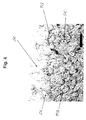
- FIG. 4 shows a micrograph of a conventional pasta product. These Picture was taken by irradiating a ca. 12 ⁇ m thick section of a Pasta product created. By staining, the protein scaffold PG and that of Starch grains SK included in the protein scaffold are made visibly different. The darker reticulated areas represent the protein scaffold PG while the lighter areas represent the starch grains SK. The upper edge of the pictured Dough structure represents the surface of the pasta product. It can be seen that the individual cells of the protein scaffold PG both inside the product and on its surface are not closed.
- FIG. 5 shows a micrograph of a pasta product produced according to the invention.
- the preparation was carried out by using a starch and Klebeerei Stamms Anlagenn Raw material in the mixing kneader according to the invention with flexing and kneading screws as well as Teflon-coated kneading mushrooms.
- the mixing kneader was at a performance powered by 9.5 kW with a throughput of 1600 kg / h. This corresponds to a specific one mechanical energy input in the mixing kneader of just under 22 kJ / kg. Between the mixing kneader and the single-screw extruder was pressed with a pressure of approx. 100 mbar degassed.
Landscapes
- Chemical & Material Sciences (AREA)
- Chemical Kinetics & Catalysis (AREA)
- Life Sciences & Earth Sciences (AREA)
- Engineering & Computer Science (AREA)
- Food Science & Technology (AREA)
- Noodles (AREA)
- Manufacturing And Processing Devices For Dough (AREA)
Abstract
Description

- Fig. 1
- eine schematische Draufsicht auf einen Abschnitt eines erfindungsgemässen Mischkneters mit aufgeschnittenem Gehäuse ist;
- Fig. 2
- eine schematische Seitenansicht einer ersten Variante eines Abschnitts einer dem erfindungsgemässen Mischkneter zugeordneten EinwellenSchneckenpresse ist;
- Fig. 3
- eine schematische Seitenansicht einer zweiten Variante eines Abschnitts einer dem erfindungsgemässen Mischkneter zugeordneten Einwellen-Schneckenpresse ist;
- Fig. 4
- eine Mikro-Aufnahme eines herkömmlichen Teigwarenproduktes zeigt; und
- Fig. 5
- eine Mikro-Aufnahme eines erfindungsgemäss hergestellten Teigwarenproduktes zeigt.
- 1
- Mischkneter
- 2
- Gehäuse
- 3
- Arbeitswelle
- 3a
- Querschnitts-Erweiterung der Arbeitswelle
- 3b
- nicht-erweiterter axialer Bereich der Arbeitswelle
- 4
- Arbeitswelle
- 4a
- Querschnitts-Erweiterung der Arbeitswelle
- 4b
- nicht-erweiterter axialer Bereich der Arbeitswelle
- 5
- zwangsfördernde Elemente / Förderschnecken
- 6
- Hohlraum
- 7
- Austragsabschnitt
- 8
- Bereich zur peristaltischen Teigknetung
- 8a
- sich verengender axialer Hohlraum-Bereich
- 8b
- axialer Engpass-Bereich
- 8c
- sich aufweitender axialer Hohlraum-Bereich
- A
- axialer Abstand der Hohlraum-Verengungen
- 9
- Bereich zum Walken bzw. Wirken des Teiges
- 9a
- Walk- und Wirkschnecken
- 9b
- Durchlässe
- 10
- Bereich zur Teigmischung und Teigförderung
- 11
- Hohlraum-Verengung
- 20
- Einwellen-Schneckenpresse
- 21
- Hohlraum-Verengung
- 22
- Gehäuse
- 23
- Arbeitswelle
- 23a
- Querschnitts-Erweiterung der Arbeitswelle
- 23b
- nicht-erweiterter axialer Bereich der Arbeitswelle
- 25
- zwangsfördernde Elemente / Förderschnecken
- 26
- Hohlraum
- 26a
- Querschnitts-Verengung des Hohlraums
- 27
- Austragsabschnitt
- 28
- Bereich zur peristaltischen Teigknetung
- 28a
- sich verengender axialer Hohlraum-Bereich
- 28b
- axialer Engpass-Bereich
- 28c
- sich aufweitender axialer Hohlraum-Bereich
- 29
- Einsatz
- 30
- Formgebungseinheit / Teigwarendüse
- A
- axialer Abstand der Hohlraum-Verengungen
- F
- Förderrichtung
- PG
- Proteingerüst (Proteinmatrix)
- SK
- Stärkekorn
Claims (53)
- Mischkneter (1 ) zur Herstellung von Rohteig, insbesondere aus stärke- und klebereiweisshaltigen Rohstoffen wie Mehl, Griess oder Dunst, mit einem Gehäuse (2), einem Rohmaterial-Zufuhrabschnitt, einem Rohteig-Austragsabschnitt sowie mindestens zwei miteinander zusammenarbeitenden, sich von dem Rohmaterial-Zufuhrabschnitt zu dem Rohteig-Austragsabschnitt innerhalb des Gehäuses in einer Förderrichtung bzw. axialen Richtung erstreckenden Arbeitswellen (3, 4), an denen Misch- und Knetelemente sowie zwangsfördernde Elemente (5) angeordnet sind, dadurch gekennzeichnet, dass der Mischkneter-Hohlraum (6) förderaufseitig von seinem Rohteig-Austragsabschnitt (7) einen Bereich (8) zur peristaltischen Teigknetung besitzt, der jeweils mindestens einen sich verengenden axialen Hohlraum-Bereich (8a) aufweist, in welchem die senkrecht zur axialen Richtung gemessene freie Querschnittsfläche des Hohlraums (6) zwischen der Oberfläche der Arbeitswellen (3, 4) und der Innenwand des Gehäuses (2) von einem Bereich mit grosser freier Querschnittsfläche zu einem Bereich mit kleiner freier Querschnittsfläche entlang der axialen Richtung abnimmt.
- Mischkneter nach Anspruch 1, dadurch gekennzeichnet, dass der Mischkneter-Hohlraum (4) in seinem Bereich (8) zur peristaltischen Teigknetung ausserdem jeweils mindestens einen sich aufweitenden axialen Hohlraum-Bereich (8c) aufweist, der sich förderabseitig an den sich verengenden axialen Hohlraum-Bereich (8a) anschliesst und in welchem die senkrecht zur axialen Richtung gemessene freie Querschnittsfläche des Hohlraums (6) zwischen der Oberfläche der Arbeitswellen (3, 4) und der Innenwand des Gehäuses (2) von einem Bereich mit kleiner freier Querschnittsfläche zu einem Bereich mit grosser freier Querschnittsfläche entlang der axialen Richtung zunimmt.
- Mischkneter nach Anspruch 2, dadurch gekennzeichnet, dass der Mischkneter-Hohlraum (6) in seinem Bereich (8) zur peristaltischen Teigknetung zwischen dem sich verengenden axialen Hohlraum-Bereich (8a) und dem sich aufweitenden axialen Hohlraum-Bereich (8c) einen axialen Engpass-Bereich (8b) aufweist, in welchem die senkrecht zur axialen Richtung gemessene freie Querschnittsfläche des Hohlraums zwischen der Oberfläche der Arbeitswellen und der Innenwand des Gehäuses entlang der axialen Richtung einen minimalen Wert hat.
- Mischkneter nach Anspruch 2, dadurch gekennzeichnet, dass der Mischkneter-Hohlraum in seinem Bereich zur peristaltischen Teigknetung mindestens eine, vorzugsweise zwei bis sechs, axial aufeinanderfolgende Hohlraum-Verengungen (11) aufweist, die jeweils aus einem sich verengenden axialen Hohlraum-Bereich (8a) sowie einem sich aufweitenden axialen Hohlraum-Bereich (8c) bestehen und zur peristaltischen Teig-Knetung dienen.
- Mischkneter nach Anspruch 3, dadurch gekennzeichnet, dass der Mischkneter-Hohlraum in seinem Bereich zur peristaltischen Teigknetung mindestens eine, vorzugsweise zwei bis sechs, axial aufeinanderfolgende Hohlraum-Verengungen (11) aufweist, die jeweils aus einem sich verengenden axialen Hohlraum-Bereich (8a), einem axialen Engpass-Bereich (8b) und einem sich aufweitenden axialen Hohlraum-Bereich (83) bestehen und zur peristaltischen Teig-Knetung dienen.
- Mischkneter nach einem der vorhergehenden Ansprüche, dadurch gekennzeichnet, dass die Arbeitswellen (3, 4) an ihrem jeweiligen Endabschnitt förderaufseitig von dem Rohteig-Austragsabschnitt rotationssymmetrisch ausgebildet sind.
- Mischkneter nach einem der vorhergehenden Ansprüche, dadurch gekennzeichnet, dass die den Oberflächen der Arbeitswellen gegenüberliegenden Bereiche der Gehäuse-Innenwand am Endabschnitt des Gehäuses (2) förderaufseitig von dem Rohteig-Austragsabschnitt rotationssymmetrisch ausgebildet sind.
- Mischkneter nach einem der Ansprüche 4 7, dadurch gekennzeichnet, dass die mehreren aufeinanderfolgenden Hohlraum-Verengungen (11) durch mehrere entlang der axialen Richtung aufeinanderfolgende Querschnitts-Erweiterungen (3a, 4a) der Arbeitswellen gebildet sind, zwischen denen sich jeweils ein nicht-erweiterter axialer Bereich der Arbeitswellen (3b, 4b) befindet.
- Mischkneter nach einem der Ansprüche 4 bis 8, dadurch gekennzeichnet, dass die mehreren aufeinanderfolgenden Hohlraum-Verengungen (11) durch mehrere entlang der axialen Richtung aufeinanderfolgende Querschnitts-Verengungen des Gehäuse-Innenraums gebildet sind.
- Mischkneter nach Anspruch 8 oder 9, dadurch gekennzeichnet, dass bei den Arbeitswellen (3, 4) die Querschnitts-Erweiterungen (3a) axial derart angeordnet sind, dass sich bei benachbarten Arbeitswellen (3, 4) die Querschnitts-Erweiterungen (31) einer Arbeitswelle (3) an einem axialen Ort befinden, an dem sich die nicht-erweiterten axialen Bereiche (4b) einer benachbarten Arbeitswelle (4) befinden.
- Mischkneter nach einem der Ansprüche 8 bis 10, dadurch gekennzeichnet, dass der axiale Abstand (A) aufeinanderfolgender Hohlraum-Verengungen (11) entlang der axialen Richtung nach und nach zunimmt.
- Mischkneter nach einem der vorhergehenden Ansprüche, dadurch gekennzeichnet, dass er förderaufseitig von seinem Bereich (8) zur peristaltischen Teigknetung einen Bereich zur Teigmischung und Teigförderung (10) besitzt, in welchem an den Arbeitswellen (3, 4) entlang der Förderrichtung aufeinanderfolgend axiale Bereiche mit Förderschnecken (5) und axiale Bereiche mit Mischblöcken angeordnet sind.
- Mischkneter nach Anspruch 12, dadurch gekennzeichnet, dass die Förderschnecken-Bereiche und die Mischblock-Bereiche an den Arbeitswellen abwechselnd aufeinanderfolgen.
- Mischkneter nach Anspruch 13, dadurch gekennzeichnet, dass der axiale Abstand aufeinanderfolgender Mischblock-Bereiche bzw. die axiale Länge des dazwischenliegenden jeweiligen Förderschnecken-Bereichs entlang der Förderrichtung zunimmt.
- Mischkneter nach einem der Ansprüche 12 bis 14, dadurch gekennzeichnet, dass der Bereich zur Teigmischung und Teigförderung zwei bis vier Förderschnecken-Bereiche und zwei bis vier Mischblock-Bereiche aufweist.
- Mischkneter nach einem der vorhergehenden Ansprüche, dadurch gekennzeichnet, dass er förderaufseitig von seinem Bereich zur peristaltischen Teigknetung einen Bereich (9) zum Walken bzw. Wirken des Teiges besitzt, in welchem an den Arbeitswellen (3, 4) entlang der Förderrichtung Walk- und Wirkschnecken (9a) angeordnet sind, die in ihren Schneckenstegen sich in axialer Richtung erstreckende Durchlässe (9b) haben, über die benachbarte Windungen eines Schneckenganges miteinander in Fluidverbindung stehen.
- Mischkneter nach Anspruch 16, dadurch gekennzeichnet, dass Durchlässe schartenartig am Kamm der Schneckenstege angeordnet sind.
- Mischkneter nach Anspruch 16 oder 17, dadurch gekennzeichnet, dass Durchlässe fensterartig zwischen dem Kern und dem Kamm der Schneckenstege angeordnet sind.
- Mischkneter nach einem der vorhergehenden Ansprüche, dadurch gekennzeichnet, das er mehrere, insbesondere zwei, gleichlaufende Arbeitswellen (3, 4) aufweist.
- Mischkneter nach einem der Ansprüche 1 bis 19, dadurch gekennzeichnet, das er mehrere, insbesondere zwei, Arbeitswellen aufweist, von denen jeweils benachbarte Arbeitswellen gegenläufig sind.
- Mischkneter nach einem der vorhergehenden Ansprüche, dadurch gekennzeichnet, dass in seinem Bereich (8) zur peristaltischen Teigknetung die Oberfläche der Arbeitswellen und/oder die der Innenwand des Gehäuses mit einer Antihaftschicht, vorzugsweise aus Teflon, überzogen ist.
- Mischkneter nach einem der vorhergehenden Ansprüche, dadurch gekennzeichnet, dass er über seinen Rohteig-Austragsabschnitt mit dem Rohteig-Zufuhrabschnitt einer Zahnradpumpe verbunden ist.
- Mischkneter nach einem der vorhergehenden Ansprüche, dadurch gekennzeichnet, dass er über seinen Rohteig-Austragsabschnitt mit dem Rohteig-Zufuhrabschnitt eines Walzenpaares verbunden ist.
- Mischkneter nach einem der vorhergehenden Ansprüche, dadurch gekennzeichnet, dass er über seinen Rohteig-Austragsabschnitt mit dem Rohteig-Zufuhrabschnitt einer Einwellen-Schneckenpresse (20) verbunden ist.
- Mischkneter nach Anspruch 24, wobei die Einwellen-Schneckenpresse (20) ein Gehäuse (22), einen Rohteig-Zufuhrabschnitt, einen Teig-Austragsabschnitt sowie eine sich von dem Rohteig-Zufuhrabschnitt zu dem Teig-Austragsabschnitt innerhalb des Gehäuses in einer Förderrichtung bzw. axialen Richtung erstreckenden Arbeitswelle (23), an der zwangsfördernde Elemente (25) angeordnet sind, dadurch gekennzeichnet, dass der Hohlraum (26) der Einwellen-Schneckenpresse (20) förderaufseitig von ihrem Teig-Austragsabschnitt einen Bereich (28) zur peristaltischen Teigknetung besitzt, der jeweils mindestens einen sich verengenden axialen Hohlraum-Bereich (28a) aufweist, in welchem die senkrecht zur axialen Richtung gemessene freie Querschnittsfläche des Hohlraums (26) zwischen der Oberfläche der Arbeitswelle (23) und der Innenwand des Gehäuses (22) von einem Bereich mit grosser freier Querschnittsfläche zu einem Bereich mit kleiner freier Querschnittsfläche entlang der axialen Richtung abnimmt.
- Mischkneter nach Anspruch 25, dadurch gekennzeichnet, dass der Hohlraum (26) der Einwellen-Schneckenpresse (20) in ihrem Bereich (28) zur peristaltischen Teigknetung ausserdem jeweils mindestens einen sich aufweitenden axialen Hohlraum-Bereich (28c) aufweist, der sich förderabseitig an den sich verengenden axialen Hohlraum-Bereich (28a) anschliesst und in welchem die senkrecht zur axialen Richtung gemessene freie Querschnittsfläche des Hohlraums (26) zwischen der Oberfläche der Arbeitswelle (23) und der Innenwand des Gehäuses (22) von einem Bereich mit kleiner freier Querschnittsfläche zu einem Bereich mit grosser freier Querschnittsfläche entlang der axialen Richtung zunimmt.
- Mischkneter nach Anspruch 26, dadurch gekennzeichnet, dass der Hohlraum der Einwellen-Schneckenpresse (20) in ihrem Bereich (28) zur peristaltischen Teigknetung zwischen dem sich verengenden axialen Hohlraum-Bereich (28a) und dem sich aufweitenden axialen Hohlraum-Bereich (28c) einen axialen Engpass-Bereich (28b) aufweist, in welchem die senkrecht zur axialen Richtung gemessene freie Querschnittsfläche des Hohlraums (26) zwischen der Oberfläche der Arbeitswelle (23) und der Innenwand des Gehäuses (22) entlang der axialen Richtung einen minimalen Wert hat.
- Mischkneter nach Anspruch 26, dadurch gekennzeichnet, dass der Hohlraum der Einwellen-Schneckenpresse (20) in ihrem Bereich (28) zur peristaltischen Teigknetung mindestens eine, vorzugsweise zwei bis sechs, axial aufeinanderfolgende Hohlraum-Verengungen aufweist, die jeweils aus einem sich verengenden axialen Hohlraum-Bereich (28a) sowie einem sich aufweitenden axialen Hohlraum-Bereich (28c) bestehen und zur peristaltischen Teig-Knetung dienen.
- Mischkneter nach Anspruch 27, dadurch gekennzeichnet, dass der Hohlraum der Einwellen-Schneckenpresse (20) in ihrem Bereich zur peristaltischen Teigknetung mindestens eine, vorzugsweise zwei bis sechs, axial aufeinanderfolgende Hohlraum-Verengungen (21) aufweist, die jeweils aus einem sich verengenden axialen Hohlraum-Bereich (28a), einem axialen Engpass-Bereich (28b) und einem sich aufweitenden axialen Hohlraum-Bereich (28c) bestehen und zur peristaltischen Teig-Knetung dienen.
- Mischkneter nach einem der Ansprüche 25 bis 29, dadurch gekennzeichnet, dass die Arbeitswelle 23 der Einwellen-Schneckenpresse 20 an ihrem Endabschnitt förderaufseitig von dem Teig-Austragsabschnitt rotationssymmetrisch ausgebildet ist.
- Mischkneter nach einem der Ansprüche 25 bis 30, dadurch gekennzeichnet, dass der Bereich der Gehäuse-Innenwand der Einwellen-Schneckenpresse (20) am Endabschnitt des Gehäuses (22) förderaufseitig von dem Teig-Austragsabschnitt rotationssymmetrisch ausgebildet ist.
- Mischkneter nach einem der Ansprüche 28 bis 31, dadurch gekennzeichnet, dass die mehreren aufeinanderfolgenden Hohlraum-Verengungen (21) der Einwellen-Schneckenpresse (20) durch mehrere entlang der axialen Richtung aufeinanderfolgende Querschnitts-Erweiterungen (23a, 23b) der Arbeitswelle gebildet sind, zwischen denen sich jeweils ein nicht-erweiterter axialer Bereich der Arbeitswelle befindet.
- Mischkneter nach einem der Ansprüche 28 bis 32, dadurch gekennzeichnet, dass die mehreren aufeinanderfolgenden Hohlraum-Verengungen der Einwellen-Schneckenpresse (20) durch mehrere entlang der axialen Richtung aufeinanderfolgende Querschnitts-Verengungen des Gehäuse-Innenraums gebildet sind.
- Mischkneter nach einem der Ansprüche 22 bis 33, dadurch gekennzeichnet, dass zwischen dem Rohteig-Austragsabschnitt des Mischkneters und dem Rohteig-Zufuhrabschnitt ein Entgasungsbereich mit Vakuumanschluss angeordnet ist.
- Mischkneter nach einem der Ansprüche 22 bis 34, dadurch gekennzeichnet, dass sich an die Einwellen-Schneckenpresse bzw. an die Zahnradpumpe bzw. an das Walzenpaar eine Formgebungseinheit (30) zur Formung des austretenden Teiges anschliesst.
- Mischkneter nach Anspruch 35, dadurch gekennzeichnet, dass die Formgebungseinheit eine Heizeinheit zum kurzzeitigen Aufheizen des durch sie hindurchtretenden Teiges aufweist.
- Mischkneter nach Anspruch 36, dadurch gekennzeichnet, dass der Heizeinheit eine Kühleinheit zum sofortigen Abkühlen des in der Heizeinheit aufgeheizten Teiges in der Teigförderrichtung nachgeschaltet ist.
- Mischkneter nach Anspruch 36 oder 37, dadurch gekennzeichnet, dass die Heizeinheit förderaufseitig und förderabseitig thermisch isoliert ist.
- Verfahren zur Herstellung von Teig, insbesondere Teigwarenteig aus stärke- und klebereiweisshaltigen Rohmaterialien, wie Mehl, Griess oder Dunst, unter Verwendung eines Mischkneters gemäss einem der Ansprüche 1 bis 39, welches die folgenden Schritte aufweist:a) Erstellen einer Rohmaterial-Trockenmischung;b) Eindosieren der Rohmaterial-Trockenmischung in den Rohmaterial-Zufuhrabschnitt des Mischkneters;c) Eindosieren von Wasser in den Mischkneter;d) Benetzen der Rohmaterial-Trockenmischung innerhalb eines Benetzungsabschnitts des Mischkneters mit Wasser mit oder ohne zusätzlichem Dämpfen;e) Mischen der benetzten und ggfs. gedämpften Rohmaterial-Mischung innerhalb eines Mischungsabschnitts des Mischkneters zu einem Rohteig;g) peristaltisches Kneten des Rohteiges in einem Peristaltik-Mischbereich des Mischkneters;h) Entgasen des Rohteiges in einem Entgasungsbereich des Mischkneters;i) Komprimieren des Rohteiges und Aufbauen von Druck im Innern des Rohteiges; undj) Formen des so gewonnenen Teiges.
- Verfahren nach Anspruch 39, dadurch gekennzeichnet, dass vor dem Schritt des peristaltischen Knetens (Schritt g) ein Schritt zum Walken bzw. Wirken des Rohteiges (Schritt f) innerhalb eines Walk- bzw. Wirkabschnitts des Mischkneters erfolgt.
- Verfahren nach Anspruch 39 oder 40, dadurch gekennzeichnet, dass die Temperatur der Rohmaterial-Mischung, des Rohteiges bzw. des Teiges während des Verfahrens stets unter 50°C gehalten wird.
- Verfahren nach Anspruch 40, dadurch gekennzeichnet, dass die maximale Temperatur während des Verfahrens kleiner als 40°C, vorzugsweise kleiner als 38°C° ist.
- Verfahren nach einem der Ansprüche 39 bis 41, dadurch gekennzeichnet, dass der spezifische mechanische Energieeintrag im Mischkneter (Leistung des Mischkneters / Nassteig-Massendurchsatz) kleiner als 25 kJ/kg, vorzugsweise kleiner als 20 kJ/kg und am bevorzugtesten kleiner als 15 kJ/kg ist.
- Verfahren nach einem der Ansprüche 40 bis 43, dadurch gekennzeichnet, dass das Entgasen des Rohteiges (Schritt h) bei einem Druck von weniger als 200 mbar erfolgt.
- Verfahren nach Anspruch 44, dadurch gekennzeichnet, dass das Entgasen des Rohteiges (Schritt h) bei einem Druck von weniger als 150 mbar, vorzugsweise von weniger als 100 mbar, erfolgt.
- Verfahren nach einem der Ansprüche 39 bis 45 zur Herstellung von Teig, insbesondere Teigwarenteig, aus stärkehaltigen, klebereiweissfreien Rohmaterialien, wie Mehl, Griess oder Dunst, unter Verwendung eines Mischkneters gemäss einem der Ansprüche 1 bis 41, welches zwischen dem Schritt des Komprimierens des Rohteiges und Aufbauen von Druck im Innern des Rohteiges (Schritt i) und dem Schritt des Formens des so gewonnenen Teiges (Schritt j) einen Schritt zum kurzzeitigen Erhitzen des Teiges auf eine Temperatur oberhalb seiner Gelatinierungstemperatur, vorzugsweise oberhalb von 65°C, insbesondere auf eine Temperatur im Bereich von 68°C bis 75°C, aufweist.
- Verfahren nach einem der Ansprüche 42 bis 45 zur Herstellung von Teig, insbesondere Teigwarenteig, aus stärkehaltigen, klebereiweissfreien Rohmaterialien, wie Mehl, Griess oder Dunst, unter Verwendung eines Mischkneters gemäss einem der Ansprüche 39 bis 41, welches während des Schrittes des Formens des so gewonnenen Teiges (Schritt j) einen Schritt zum kurzzeitigen Erhitzen des Teiges auf eine Temperatur oberhalb seiner Gelatinierungstemperatur, vorzugsweise oberhalb von 65°C, insbesondere auf eine Temperatur im Bereich von 68°C bis 75°C, aufweist.
- Verfahren nach Anspruch 47, dadurch gekennzeichnet, dass während des kurzzeitigen Erhitzens des Teiges der geformte Teig, insbesondere die geformte Langware oder die geformte Kurzware, nur an seiner Oberfläche auf eine Temperatur oberhalb der Gelatinierungstemperatur, vorzugsweise oberhalb von 65°C, insbesondere auf eine Temperatur im Bereich von 68°C bis 75°C, erhitzt wird.
- Verfahren nach einem der Ansprüche 42 bis 48, dadurch gekennzeichnet, dass das Walken bzw. Wirken des Rohteiges (Schritt f) durch Zerteilen und anschliessendes Vereinen der Rohteig-Strömung in dem Walk- und Wirkabschnitt des Mischkneters erfolgt.
- Verfahren nach Anspruch 49, dadurch gekennzeichnet, dass das Walken bzw. Wirken des Rohteiges (Schritt f) durch mehrmalig aufeinanderfolgendes abwechselndes Zerteilen und Vereinen der Rohteig-Strömung in dem Walk- und Wirkabschnitt des Mischkneters erfolgt.
- Verfahren nach einem der Ansprüche 42 bis 50, dadurch gekennzeichnet, dass das peristaltische Mischen des Rohteiges (Schritt g) durch Dehnen und Drücken sowie anschliessendes Entspannen und Rückvermischen der Rohteig-Strömung in dem Peristaltik-Mischbereich des Mischkneters erfolgt.
- Verfahren nach Anspruch 51, dadurch gekennzeichnet, dass das peristaltische Mischen des Rohteiges (Schritt g) durch mehrmalig aufeinanderfolgendes abwechselndes Dehnen und Komprimieren ("Stauchen") der Rohteig-Strömung in dem Peristaltik-Mischbereich des Mischkneters erfolgt.
- Verfahren nach einem der Ansprüche 46 bis 52, dadurch gekennzeichnet, dass als stärkehaltiges, klebereiweissfreies Rohmaterial mindestens ein Material aus der folgenden Gruppe verwendet wird:Mais, Reis, Hirse, Gerste, jeweils in Form von Griess, Mehl oder Dunst;

Applications Claiming Priority (4)
| Application Number | Priority Date | Filing Date | Title |
|---|---|---|---|
| DE10343711 | 2003-09-18 | ||
| DE10343711 | 2003-09-18 | ||
| DE102004012581A DE102004012581A1 (de) | 2003-09-18 | 2004-03-12 | Mischkneter und Verfahren zur Herstellung von Rohteig zur Teigwarenherstellung |
| DE102204012581 | 2004-03-12 |
Publications (2)
| Publication Number | Publication Date |
|---|---|
| EP1516661A1 true EP1516661A1 (de) | 2005-03-23 |
| EP1516661B1 EP1516661B1 (de) | 2006-03-29 |
Family
ID=34195762
Family Applications (1)
| Application Number | Title | Priority Date | Filing Date |
|---|---|---|---|
| EP04104181A Expired - Lifetime EP1516661B1 (de) | 2003-09-18 | 2004-09-01 | Mischkneter und Verfahren zur Herstellung von Rohteig zur Teigwarenherstellung |
Country Status (3)
| Country | Link |
|---|---|
| EP (1) | EP1516661B1 (de) |
| AT (1) | ATE321604T1 (de) |
| DE (1) | DE502004000401D1 (de) |
Cited By (1)
| Publication number | Priority date | Publication date | Assignee | Title |
|---|---|---|---|---|
| WO2010046451A3 (de) * | 2008-10-22 | 2010-12-09 | Bühler AG | Verfahren und vorrichtung zur herstellung von teig |
Citations (5)
| Publication number | Priority date | Publication date | Assignee | Title |
|---|---|---|---|---|
| GB677208A (en) * | 1949-10-01 | 1952-08-13 | Celanese Corp | Mixing apparatus |
| CH484366A (de) * | 1966-12-29 | 1970-01-15 | Metallgesellschaft Ag | Vorrichtung zur mechanischen oder thermischen Behandlung von flüssigen, förderfähigen halbfesten und festen Stoffen |
| US3884881A (en) * | 1973-05-18 | 1975-05-20 | Du Pont | Preparation of poly(p-phenylene terephthalamide) by mixing solution of p-phenylene diamine with molten terephthaloyl chloride |
| EP0426766B1 (de) * | 1989-05-25 | 1994-02-02 | Bühler Ag | Mischkneter-vorrichtung und verfahren zur herstellung von teig, insbesondere für teigwaren |
| US20020075755A1 (en) * | 2000-12-19 | 2002-06-20 | Wenger Manufacturing, Inc. | System for homogeneously mixing plural incoming product streams of different composition |
-
2004
- 2004-09-01 AT AT04104181T patent/ATE321604T1/de not_active IP Right Cessation
- 2004-09-01 DE DE502004000401T patent/DE502004000401D1/de not_active Expired - Fee Related
- 2004-09-01 EP EP04104181A patent/EP1516661B1/de not_active Expired - Lifetime
Patent Citations (5)
| Publication number | Priority date | Publication date | Assignee | Title |
|---|---|---|---|---|
| GB677208A (en) * | 1949-10-01 | 1952-08-13 | Celanese Corp | Mixing apparatus |
| CH484366A (de) * | 1966-12-29 | 1970-01-15 | Metallgesellschaft Ag | Vorrichtung zur mechanischen oder thermischen Behandlung von flüssigen, förderfähigen halbfesten und festen Stoffen |
| US3884881A (en) * | 1973-05-18 | 1975-05-20 | Du Pont | Preparation of poly(p-phenylene terephthalamide) by mixing solution of p-phenylene diamine with molten terephthaloyl chloride |
| EP0426766B1 (de) * | 1989-05-25 | 1994-02-02 | Bühler Ag | Mischkneter-vorrichtung und verfahren zur herstellung von teig, insbesondere für teigwaren |
| US20020075755A1 (en) * | 2000-12-19 | 2002-06-20 | Wenger Manufacturing, Inc. | System for homogeneously mixing plural incoming product streams of different composition |
Cited By (1)
| Publication number | Priority date | Publication date | Assignee | Title |
|---|---|---|---|---|
| WO2010046451A3 (de) * | 2008-10-22 | 2010-12-09 | Bühler AG | Verfahren und vorrichtung zur herstellung von teig |
Also Published As
| Publication number | Publication date |
|---|---|
| DE502004000401D1 (de) | 2006-05-18 |
| ATE321604T1 (de) | 2006-04-15 |
| EP1516661B1 (de) | 2006-03-29 |
Similar Documents
| Publication | Publication Date | Title |
|---|---|---|
| DE3447533C2 (de) | Doppelschnecken-Nudelherstellungsverfahren | |
| DE4325514C1 (de) | Kochextruder zur Herstellung von thermisch behandelten Biopolymeren sowie Verfahren zum Kochextrudieren von Biopolymeren | |
| EP0426766B2 (de) | Mischkneter-vorrichtung und verfahren zur herstellung von teig, insbesondere für teigwaren | |
| EP0041641B1 (de) | Verfahren und Doppelschneckenextruder zur Verarbeitung von trockenen, pulver- bzw. mehlförmigen Substanzen zu Lebens- und Futtermittel in verzehrgerechter Form | |
| DE60129353T2 (de) | Extrusionsverfahren, vorrichtung und erzeugnis | |
| DE60224986T2 (de) | Verfahren und vorrichtung zur kontinuierlichen herstellung von pellets zur herstellung von snackprodukten | |
| DE69520167T2 (de) | Herstellung von Teigwaren | |
| DE69616298T2 (de) | Vorrichtung zur Herstellung eines extrudierten Nahrungsprodukt | |
| US9931603B2 (en) | Method and apparatus for extrusion processing of high fiber content foods | |
| EP2782441A1 (de) | Einschneckenextruder und verfahren zum herstellen eines plastifizierten lebensmittelproduktes | |
| EP1047307A1 (de) | Verfahren zur herstellung eines futter- oder lebensmittels sowie danach herstellbares produkt | |
| DE602005004359T2 (de) | Chargenmischer und Rotor dafür | |
| EP1715760B1 (de) | Verfahren zur herstellung von teigwaren, danach erhältliche teigwaren und anlage zur durchführung des verfahrens | |
| DE69520491T2 (de) | Verfahren zur Herstellung von gekochten Getreideprodukten | |
| DE69011680T2 (de) | Verfahren zur Herstellung von Teigwaren durch Extrusion und Einrichtung dafür. | |
| EP1516661B1 (de) | Mischkneter und Verfahren zur Herstellung von Rohteig zur Teigwarenherstellung | |
| DE102008043090A1 (de) | Verfahren und Vorrichtung zur Herstellung von Teig | |
| EP1027836A2 (de) | Verfahren und Vorrichtung zur Herstellung von Zwischenprodukten und Mischfutterprodukten für Tiere | |
| DE3023124C2 (de) | Extrudierverfahren und Extrudieranlage zur Durchführung des Verfahrens | |
| DE19913514C1 (de) | Verfahren und Vorrichtung zur Herstellung von Zwischenprodukten und Mischfutterfertigprodukten für Tiere | |
| DE102023106028A1 (de) | Verfahren zum erzeugen eines texturats und proteinhaltiges texturat | |
| CN204640883U (zh) | 单螺杆食品挤出机 | |
| DE102023106032A1 (de) | Verfahren zum erzeugen eines texturats und extruderanordnung | |
| DE102012112747A1 (de) | Plastifizierzylinder einer Spritzgießmaschine | |
| DE102004012589A1 (de) | Herstellung von Teigwaren aus kleberelweiss-freien Rohmaterialien |
Legal Events
| Date | Code | Title | Description |
|---|---|---|---|
| PUAI | Public reference made under article 153(3) epc to a published international application that has entered the european phase |
Free format text: ORIGINAL CODE: 0009012 |
|
| 17P | Request for examination filed |
Effective date: 20040901 |
|
| AK | Designated contracting states |
Kind code of ref document: A1 Designated state(s): AT BE BG CH CY CZ DE DK EE ES FI FR GB GR HU IE IT LI LU MC NL PL PT RO SE SI SK TR |
|
| AX | Request for extension of the european patent |
Extension state: AL HR LT LV MK |
|
| GRAP | Despatch of communication of intention to grant a patent |
Free format text: ORIGINAL CODE: EPIDOSNIGR1 |
|
| AKX | Designation fees paid |
Designated state(s): AT BE BG CH CY CZ DE DK EE ES FI FR GB GR HU IE IT LI LU MC NL PL PT RO SE SI SK TR |
|
| GRAS | Grant fee paid |
Free format text: ORIGINAL CODE: EPIDOSNIGR3 |
|
| GRAA | (expected) grant |
Free format text: ORIGINAL CODE: 0009210 |
|
| AK | Designated contracting states |
Kind code of ref document: B1 Designated state(s): AT BE BG CH CY CZ DE DK EE ES FI FR GB GR HU IE IT LI LU MC NL PL PT RO SE SI SK TR |
|
| PG25 | Lapsed in a contracting state [announced via postgrant information from national office to epo] |
Ref country code: IT Free format text: LAPSE BECAUSE OF FAILURE TO SUBMIT A TRANSLATION OF THE DESCRIPTION OR TO PAY THE FEE WITHIN THE PRESCRIBED TIME-LIMIT;WARNING: LAPSES OF ITALIAN PATENTS WITH EFFECTIVE DATE BEFORE 2007 MAY HAVE OCCURRED AT ANY TIME BEFORE 2007. THE CORRECT EFFECTIVE DATE MAY BE DIFFERENT FROM THE ONE RECORDED. Effective date: 20060329 Ref country code: NL Free format text: LAPSE BECAUSE OF FAILURE TO SUBMIT A TRANSLATION OF THE DESCRIPTION OR TO PAY THE FEE WITHIN THE PRESCRIBED TIME-LIMIT Effective date: 20060329 Ref country code: IE Free format text: LAPSE BECAUSE OF FAILURE TO SUBMIT A TRANSLATION OF THE DESCRIPTION OR TO PAY THE FEE WITHIN THE PRESCRIBED TIME-LIMIT Effective date: 20060329 Ref country code: RO Free format text: LAPSE BECAUSE OF FAILURE TO SUBMIT A TRANSLATION OF THE DESCRIPTION OR TO PAY THE FEE WITHIN THE PRESCRIBED TIME-LIMIT Effective date: 20060329 Ref country code: GB Free format text: LAPSE BECAUSE OF FAILURE TO SUBMIT A TRANSLATION OF THE DESCRIPTION OR TO PAY THE FEE WITHIN THE PRESCRIBED TIME-LIMIT Effective date: 20060329 Ref country code: PL Free format text: LAPSE BECAUSE OF FAILURE TO SUBMIT A TRANSLATION OF THE DESCRIPTION OR TO PAY THE FEE WITHIN THE PRESCRIBED TIME-LIMIT Effective date: 20060329 Ref country code: SI Free format text: LAPSE BECAUSE OF FAILURE TO SUBMIT A TRANSLATION OF THE DESCRIPTION OR TO PAY THE FEE WITHIN THE PRESCRIBED TIME-LIMIT Effective date: 20060329 Ref country code: SK Free format text: LAPSE BECAUSE OF FAILURE TO SUBMIT A TRANSLATION OF THE DESCRIPTION OR TO PAY THE FEE WITHIN THE PRESCRIBED TIME-LIMIT Effective date: 20060329 |
|
| REG | Reference to a national code |
Ref country code: GB Ref legal event code: FG4D Free format text: NOT ENGLISH |
|
| REG | Reference to a national code |
Ref country code: CH Ref legal event code: EP |
|
| REG | Reference to a national code |
Ref country code: IE Ref legal event code: FG4D Free format text: LANGUAGE OF EP DOCUMENT: GERMAN |
|
| REF | Corresponds to: |
Ref document number: 502004000401 Country of ref document: DE Date of ref document: 20060518 Kind code of ref document: P |
|
| PG25 | Lapsed in a contracting state [announced via postgrant information from national office to epo] |
Ref country code: SE Free format text: LAPSE BECAUSE OF FAILURE TO SUBMIT A TRANSLATION OF THE DESCRIPTION OR TO PAY THE FEE WITHIN THE PRESCRIBED TIME-LIMIT Effective date: 20060629 Ref country code: BG Free format text: LAPSE BECAUSE OF FAILURE TO SUBMIT A TRANSLATION OF THE DESCRIPTION OR TO PAY THE FEE WITHIN THE PRESCRIBED TIME-LIMIT Effective date: 20060629 Ref country code: DK Free format text: LAPSE BECAUSE OF FAILURE TO SUBMIT A TRANSLATION OF THE DESCRIPTION OR TO PAY THE FEE WITHIN THE PRESCRIBED TIME-LIMIT Effective date: 20060629 |
|
| PG25 | Lapsed in a contracting state [announced via postgrant information from national office to epo] |
Ref country code: ES Free format text: LAPSE BECAUSE OF FAILURE TO SUBMIT A TRANSLATION OF THE DESCRIPTION OR TO PAY THE FEE WITHIN THE PRESCRIBED TIME-LIMIT Effective date: 20060710 |
|
| PG25 | Lapsed in a contracting state [announced via postgrant information from national office to epo] |
Ref country code: PT Free format text: LAPSE BECAUSE OF FAILURE TO SUBMIT A TRANSLATION OF THE DESCRIPTION OR TO PAY THE FEE WITHIN THE PRESCRIBED TIME-LIMIT Effective date: 20060829 |
|
| PG25 | Lapsed in a contracting state [announced via postgrant information from national office to epo] |
Ref country code: MC Free format text: LAPSE BECAUSE OF NON-PAYMENT OF DUE FEES Effective date: 20060930 Ref country code: BE Free format text: LAPSE BECAUSE OF NON-PAYMENT OF DUE FEES Effective date: 20060930 |
|
| NLV1 | Nl: lapsed or annulled due to failure to fulfill the requirements of art. 29p and 29m of the patents act | ||
| GBV | Gb: ep patent (uk) treated as always having been void in accordance with gb section 77(7)/1977 [no translation filed] |
Effective date: 20060329 |
|
| REG | Reference to a national code |
Ref country code: IE Ref legal event code: FD4D |
|
| PLBE | No opposition filed within time limit |
Free format text: ORIGINAL CODE: 0009261 |
|
| STAA | Information on the status of an ep patent application or granted ep patent |
Free format text: STATUS: NO OPPOSITION FILED WITHIN TIME LIMIT |
|
| PG25 | Lapsed in a contracting state [announced via postgrant information from national office to epo] |
Ref country code: DE Free format text: LAPSE BECAUSE OF NON-PAYMENT OF DUE FEES Effective date: 20070403 |
|
| 26N | No opposition filed |
Effective date: 20070102 |
|
| EN | Fr: translation not filed | ||
| PG25 | Lapsed in a contracting state [announced via postgrant information from national office to epo] |
Ref country code: AT Free format text: LAPSE BECAUSE OF NON-PAYMENT OF DUE FEES Effective date: 20060901 |
|
| BERE | Be: lapsed |
Owner name: BUHLER A.G. Effective date: 20060930 |
|
| PG25 | Lapsed in a contracting state [announced via postgrant information from national office to epo] |
Ref country code: FR Free format text: LAPSE BECAUSE OF FAILURE TO SUBMIT A TRANSLATION OF THE DESCRIPTION OR TO PAY THE FEE WITHIN THE PRESCRIBED TIME-LIMIT Effective date: 20070309 Ref country code: GR Free format text: LAPSE BECAUSE OF FAILURE TO SUBMIT A TRANSLATION OF THE DESCRIPTION OR TO PAY THE FEE WITHIN THE PRESCRIBED TIME-LIMIT Effective date: 20060630 Ref country code: CZ Free format text: LAPSE BECAUSE OF FAILURE TO SUBMIT A TRANSLATION OF THE DESCRIPTION OR TO PAY THE FEE WITHIN THE PRESCRIBED TIME-LIMIT Effective date: 20060329 |
|
| PG25 | Lapsed in a contracting state [announced via postgrant information from national office to epo] |
Ref country code: FI Free format text: LAPSE BECAUSE OF FAILURE TO SUBMIT A TRANSLATION OF THE DESCRIPTION OR TO PAY THE FEE WITHIN THE PRESCRIBED TIME-LIMIT Effective date: 20060329 Ref country code: EE Free format text: LAPSE BECAUSE OF FAILURE TO SUBMIT A TRANSLATION OF THE DESCRIPTION OR TO PAY THE FEE WITHIN THE PRESCRIBED TIME-LIMIT Effective date: 20060329 |
|
| PG25 | Lapsed in a contracting state [announced via postgrant information from national office to epo] |
Ref country code: HU Free format text: LAPSE BECAUSE OF FAILURE TO SUBMIT A TRANSLATION OF THE DESCRIPTION OR TO PAY THE FEE WITHIN THE PRESCRIBED TIME-LIMIT Effective date: 20060930 Ref country code: LU Free format text: LAPSE BECAUSE OF NON-PAYMENT OF DUE FEES Effective date: 20060901 Ref country code: TR Free format text: LAPSE BECAUSE OF FAILURE TO SUBMIT A TRANSLATION OF THE DESCRIPTION OR TO PAY THE FEE WITHIN THE PRESCRIBED TIME-LIMIT Effective date: 20060329 |
|
| PG25 | Lapsed in a contracting state [announced via postgrant information from national office to epo] |
Ref country code: FR Free format text: LAPSE BECAUSE OF FAILURE TO SUBMIT A TRANSLATION OF THE DESCRIPTION OR TO PAY THE FEE WITHIN THE PRESCRIBED TIME-LIMIT Effective date: 20060329 Ref country code: CY Free format text: LAPSE BECAUSE OF FAILURE TO SUBMIT A TRANSLATION OF THE DESCRIPTION OR TO PAY THE FEE WITHIN THE PRESCRIBED TIME-LIMIT Effective date: 20060329 |
|
| REG | Reference to a national code |
Ref country code: CH Ref legal event code: PL |
|
| PG25 | Lapsed in a contracting state [announced via postgrant information from national office to epo] |
Ref country code: CH Free format text: LAPSE BECAUSE OF NON-PAYMENT OF DUE FEES Effective date: 20060930 Ref country code: LI Free format text: LAPSE BECAUSE OF NON-PAYMENT OF DUE FEES Effective date: 20060930 |
|
| PG25 | Lapsed in a contracting state [announced via postgrant information from national office to epo] |
Ref country code: LI Free format text: LAPSE BECAUSE OF NON-PAYMENT OF DUE FEES Effective date: 20080930 Ref country code: CH Free format text: LAPSE BECAUSE OF NON-PAYMENT OF DUE FEES Effective date: 20080930 |