EP1516573A2 - Aspirateur - Google Patents
Aspirateur Download PDFInfo
- Publication number
- EP1516573A2 EP1516573A2 EP04019167A EP04019167A EP1516573A2 EP 1516573 A2 EP1516573 A2 EP 1516573A2 EP 04019167 A EP04019167 A EP 04019167A EP 04019167 A EP04019167 A EP 04019167A EP 1516573 A2 EP1516573 A2 EP 1516573A2
- Authority
- EP
- European Patent Office
- Prior art keywords
- liquid
- separation chamber
- air
- stream
- vacuum cleaner
- Prior art date
- Legal status (The legal status is an assumption and is not a legal conclusion. Google has not performed a legal analysis and makes no representation as to the accuracy of the status listed.)
- Withdrawn
Links
Images


Classifications
-
- A—HUMAN NECESSITIES
- A47—FURNITURE; DOMESTIC ARTICLES OR APPLIANCES; COFFEE MILLS; SPICE MILLS; SUCTION CLEANERS IN GENERAL
- A47L—DOMESTIC WASHING OR CLEANING; SUCTION CLEANERS IN GENERAL
- A47L9/00—Details or accessories of suction cleaners, e.g. mechanical means for controlling the suction or for effecting pulsating action; Storing devices specially adapted to suction cleaners or parts thereof; Carrying-vehicles specially adapted for suction cleaners
- A47L9/10—Filters; Dust separators; Dust removal; Automatic exchange of filters
- A47L9/16—Arrangement or disposition of cyclones or other devices with centrifugal action
- A47L9/165—Construction of inlets
-
- A—HUMAN NECESSITIES
- A47—FURNITURE; DOMESTIC ARTICLES OR APPLIANCES; COFFEE MILLS; SPICE MILLS; SUCTION CLEANERS IN GENERAL
- A47L—DOMESTIC WASHING OR CLEANING; SUCTION CLEANERS IN GENERAL
- A47L7/00—Suction cleaners adapted for additional purposes; Tables with suction openings for cleaning purposes; Containers for cleaning articles by suction; Suction cleaners adapted to cleaning of brushes; Suction cleaners adapted to taking-up liquids
- A47L7/0004—Suction cleaners adapted to take up liquids, e.g. wet or dry vacuum cleaners
- A47L7/0023—Recovery tanks
- A47L7/0028—Security means, e.g. float valves or level switches for preventing overflow
-
- A—HUMAN NECESSITIES
- A47—FURNITURE; DOMESTIC ARTICLES OR APPLIANCES; COFFEE MILLS; SPICE MILLS; SUCTION CLEANERS IN GENERAL
- A47L—DOMESTIC WASHING OR CLEANING; SUCTION CLEANERS IN GENERAL
- A47L9/00—Details or accessories of suction cleaners, e.g. mechanical means for controlling the suction or for effecting pulsating action; Storing devices specially adapted to suction cleaners or parts thereof; Carrying-vehicles specially adapted for suction cleaners
- A47L9/10—Filters; Dust separators; Dust removal; Automatic exchange of filters
- A47L9/19—Means for monitoring filtering operation
-
- A—HUMAN NECESSITIES
- A47—FURNITURE; DOMESTIC ARTICLES OR APPLIANCES; COFFEE MILLS; SPICE MILLS; SUCTION CLEANERS IN GENERAL
- A47L—DOMESTIC WASHING OR CLEANING; SUCTION CLEANERS IN GENERAL
- A47L9/00—Details or accessories of suction cleaners, e.g. mechanical means for controlling the suction or for effecting pulsating action; Storing devices specially adapted to suction cleaners or parts thereof; Carrying-vehicles specially adapted for suction cleaners
- A47L9/28—Installation of the electric equipment, e.g. adaptation or attachment to the suction cleaner; Controlling suction cleaners by electric means
- A47L9/2805—Parameters or conditions being sensed
-
- A—HUMAN NECESSITIES
- A47—FURNITURE; DOMESTIC ARTICLES OR APPLIANCES; COFFEE MILLS; SPICE MILLS; SUCTION CLEANERS IN GENERAL
- A47L—DOMESTIC WASHING OR CLEANING; SUCTION CLEANERS IN GENERAL
- A47L9/00—Details or accessories of suction cleaners, e.g. mechanical means for controlling the suction or for effecting pulsating action; Storing devices specially adapted to suction cleaners or parts thereof; Carrying-vehicles specially adapted for suction cleaners
- A47L9/28—Installation of the electric equipment, e.g. adaptation or attachment to the suction cleaner; Controlling suction cleaners by electric means
- A47L9/2836—Installation of the electric equipment, e.g. adaptation or attachment to the suction cleaner; Controlling suction cleaners by electric means characterised by the parts which are controlled
- A47L9/2842—Suction motors or blowers
-
- A—HUMAN NECESSITIES
- A47—FURNITURE; DOMESTIC ARTICLES OR APPLIANCES; COFFEE MILLS; SPICE MILLS; SUCTION CLEANERS IN GENERAL
- A47L—DOMESTIC WASHING OR CLEANING; SUCTION CLEANERS IN GENERAL
- A47L9/00—Details or accessories of suction cleaners, e.g. mechanical means for controlling the suction or for effecting pulsating action; Storing devices specially adapted to suction cleaners or parts thereof; Carrying-vehicles specially adapted for suction cleaners
- A47L9/28—Installation of the electric equipment, e.g. adaptation or attachment to the suction cleaner; Controlling suction cleaners by electric means
- A47L9/2857—User input or output elements for control, e.g. buttons, switches or displays
Definitions
- the invention relates to vacuum cleaners, and in particular to wet/dry vacuum cleaners.
- the invention also relates to so-called cyclonic vacuum cleaners which use a circulating airflow to separate contaminants from the air.
- Wet/dry vacuum cleaners are well-known. Such vacuum cleaners separate liquid and contaminants from a suction stream of air. The liquid and contaminants are collected in a collection chamber for later emptying. It is also known to put a level switch, such as a float switch, in the collection chamber to stop the vacuum cleaner motor when a level of liquid in the collection chamber rises to a predetermined level.
- a level switch such as a float switch
- Cyclonic vacuum cleaners that use circular airflow within a separation chamber to separate liquid and contaminants from a stream of air are also known.
- a separation chamber is provided in an upper portion of a cyclone housing, with the lower portion of the housing forming a collection chamber for the separated liquid and contaminants.
- the circular airflow causes circular movement of water in the collection chamber.
- a problem with placing a level switch within the collection chamber of a cyclone vacuum cleaner is that the circular movement of water in the collection chamber results in inaccurate level measurement.
- a second problem is that it is difficult to get a stream of air laden with heavy water to move in a circular motion within the separation chamber in order to separate the liquid and contaminants from the air stream.
- a vacuum cleaner comprising: a housing having a separation chamber for separating liquid and contaminants from a stream of air, and a collection chamber for collecting the separated liquid and contaminants, a floor unit having a suction opening, a passage between the suction opening and separation chamber, a suction source for establishing and maintaining the stream of air from the suction opening to the separation chamber, a controller for stopping the suction source when a level of liquid in the collection chamber rises to a predetermined level, and a protective structure to shield at least a portion of the controller from circular movement of the liquid.
- the controller is a float and a switch.
- the protective structure is a float guide for constraining the float therein.
- an upstream wall of the float guide is solid for defecting the circular movement of the liquid, and a downstream wall of the float guide has a opening for allowing a liquid level in the float guide to rise with the level of liquid in the collection chamber.
- the switch is positioned on an outside wall of the collection chamber, and a lever is positioned through an opening in the wall for activating the switch.
- the float has a rod for engaging the lever.
- the float guide is a tube with openings at a top and bottom thereof.
- a vacuum cleaner comprising: a housing having a separation chamber for separating liquid and contaminants from a stream of air, and a collection chamber for collecting the separated liquid and contaminants, a floor unit having a suction opening, a passage between the suction opening and separation chamber, a suction source for establishing and maintaining the stream of air from the suction opening to the separation chamber, a float arranged to rise when a level of liquid in the collection chamber rises, a protective structure for constraining the float therein and having an upstream wall for defecting circular movement of the liquid, a switch positioned on an outside wall of the collection chamber and for stopping the suction source, and a lever positioned through an opening in the wall for activating the switch when the level of liquid rises to a predetermined level.
- a vacuum cleaner comprising: a housing having a separation chamber for separating liquid and contaminants from a stream of air, and a collection chamber for collecting the separated liquid and contaminants, a floor unit having a suction opening, a passage between the suction opening and separation chamber, a suction source for establishing and maintaining the stream of air from the suction opening to the separation chamber, and a structure for defining a path for the stream of air along an internal perimeter of the separation chamber.
- the structure is a cylindrical wall positioned within the separation chamber.
- an air inlet of the separation chamber defines an inlet path for the stream of air that is tangential to the path along the internal perimeter of the separation chamber.
- the air inlet has a restriction for increasing a velocity of the stream of air within the separation chamber.
- the vacuum cleaner further includes a float arranged to rise when a level of liquid in the collection chamber rises, a protective structure for constraining the float therein and having an upstream wall for defecting circular movement of the liquid, a switch positioned on an outside wall of the collection chamber and arranged for stopping the suction source, and a lever positioned through an opening in the wall for activating the switch when the level of liquid rises to a predetermined level.
- a vacuum cleaner comprising: a housing having a separation chamber for separating liquid and contaminants from a stream of air, and a collection chamber for collecting the separated liquid and contaminants, a floor unit having a suction opening, a passage between the suction opening and separation chamber, a suction source for establishing and maintaining the stream of air from the suction opening to the separation chamber, a structure for defining a path for the stream of air along an internal perimeter of the separation chamber, a controller for stopping the suction source when a level of liquid in the collection chamber rises to a predetermined level, and a protective structure to shield at least a portion of the controller from circular movement of the liquid.
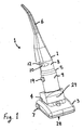
- a vacuum cleaner 1 has an upright unit 2 and a floor unit 3 joined at a pivot position 4.
- the upright unit 2 includes a cyclone housing 5 that defines an upper separation chamber 8 for separating liquid and contaminants from an air stream and a lower collection chamber 9 for collecting the separated liquid and contaminants.
- a handle 6 At the distal end of upper unit 2 is a handle 6.
- the floor unit 3 has wheels 7 for travelling along a floor surface.
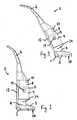
- a suction opening 28 Through which liquid and contaminants are drawn in with a stream of air.
- the stream of air, with liquid and contaminants, travels through a passage 12 to an inlet 10 of the separation chamber 8.
- a suction motor 29 Located at the base of upright unit 2 is a suction motor 29 for establishing and maintaining the stream of air from the suction opening 28 through passage 12 to the inlet 10 of separation chamber 8.
- cyclone housing 5 is a substantially cylindrical shaped hollow body.
- the upper portion of housing 5 defining the separation chamber 8 has a smaller diameter than the lower portion defining the collection chamber 9.
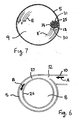
- Within the separation chamber 8 is a cylindrical wall 26 that defines an air stream path 27 around the internal perimeter of the separation chamber 8.
- the air inlet 10 is provided in a circumferential wall of the separation chamber 8 and defines an inlet air stream path tangential to the internal perimeter of separation chamber 8.
- the opening 32 of air inlet 10 is smaller than then passage 12 to restrict the stream of air entering the separation chamber 8.
- the velocity of the stream of air increases as it enters air stream path 27 through the restriction of smaller opening 32.
- the stream of air travels around the airflow path 27 created by cylindrical wall 26 as indicated by arrow B. This sets up a circulating airflow for separating liquid and contaminants from the steam of air.
- the higher velocity of the stream of air within separation chamber 8 increases separation performance.
- the circulating stream of air spirals downwards within the cyclonic housing 5 to the collection chamber 9 as indicated by path B.
- the stream of air then travels up the axial center of the cyclonic housing 5 in the direction of arrow C and out through the outlet 11 of separation chamber 8 as indicated at arrow D.
- a float guide 13 Positioned within separation chamber 9, and against an internal wall thereof, is a float guide 13 in the form of a tube. Positioned within float guide 13 is a buoyant float 14. The float has an upwardly extending rod 15. Extending radially from the rod proximate its top end are guide arms 20 which contact the interior wall of float guide 13 for supporting the upper end of rod 15.
- a switch 17 Located on the exterior wall of the housing 5 proximate the top of collection chamber 9 is a switch 17.
- the switch 17 is arranged to stop the suction motor 29 when it is operated.
- a cover 19 is provided over the switch 17 to stop dust and dirt interfering with its operation, and to prevent contact with electrical parts.
- a lever 16 is mounted on a pivot 22 and extends through an opening 30 in the wall of cyclone housing 5 into an upper part of the float guide 13. As the level of liquid in the collection chamber 9 rises so does float 14. When a predetermined level of liquid is reached the top of rod 15 engages with an end 21 of lever 16 causing it to pivot and depress operating lever 18 of switch 17. When the switch 17 is operated it stops suction motor 29 to prevent overflow of liquid the collection chamber 9.
- the float guide 13 protects the float from the circular movement of the liquid in collection chamber 9.
- the hemispherical portion 31 of the float guide wall which faces upstream towards circular flow E of the liquid is solid to deflect the circular movement of the liquid away from the float 14.
- the hemispherical portion 31 of the wall which is facing downstream of the circular liquid flow E has a plurality of elongate openings 25 which allow the inlet of water to the float guide 13 so that the level of liquid in the float guide 13 rises with the level of liquid in the separation chamber 9.
- the bottom end of the float guide 13 also has a plurality of openings 24.
- a slot 23 extends longitudinally along the float guide wall from its open top end. Slot 23 is positioned adjacent opening 30 in the housing wall so that lever 16 extends into the float guide 13.
Landscapes
- Engineering & Computer Science (AREA)
- Mechanical Engineering (AREA)
- Filters For Electric Vacuum Cleaners (AREA)
- Separating Particles In Gases By Inertia (AREA)
Applications Claiming Priority (2)
| Application Number | Priority Date | Filing Date | Title |
|---|---|---|---|
| US10/665,544 US7293324B2 (en) | 2003-09-19 | 2003-09-19 | Vacuum cleaner with level control |
| US665544 | 2003-09-19 |
Publications (2)
| Publication Number | Publication Date |
|---|---|
| EP1516573A2 true EP1516573A2 (fr) | 2005-03-23 |
| EP1516573A3 EP1516573A3 (fr) | 2006-12-20 |
Family
ID=34194764
Family Applications (1)
| Application Number | Title | Priority Date | Filing Date |
|---|---|---|---|
| EP04019167A Withdrawn EP1516573A3 (fr) | 2003-09-19 | 2004-08-12 | Aspirateur |
Country Status (4)
| Country | Link |
|---|---|
| US (1) | US7293324B2 (fr) |
| EP (1) | EP1516573A3 (fr) |
| CN (1) | CN1596814B (fr) |
| AU (1) | AU2004212518A1 (fr) |
Cited By (2)
| Publication number | Priority date | Publication date | Assignee | Title |
|---|---|---|---|---|
| DE102008004393B3 (de) * | 2008-01-14 | 2009-07-16 | Miele & Cie. Kg | Vorrichtung zum Abscheiden von Staub aus staubbeladener Luft, insbesondere zur Verwendung in einem Staubsauger |
| ITMI20090644A1 (it) * | 2009-04-20 | 2010-10-21 | Progettazioni Innovative Di Gandini L & C S A S | Aspiratore a ciclone |
Families Citing this family (14)
| Publication number | Priority date | Publication date | Assignee | Title |
|---|---|---|---|---|
| KR101566411B1 (ko) | 2009-05-19 | 2015-11-06 | 삼성전자주식회사 | 진공청소기의 습식집진장치 |
| AU2010214785B2 (en) * | 2009-09-10 | 2014-06-12 | Bissell Inc. | Extraction cleaner and centrifugal air/water separator therefor |
| DE102010026831B4 (de) * | 2010-07-12 | 2021-08-12 | Paprima Industries Inc. | Abflussvorrichtung für und Verfahren zum Abtransport von Schmutzpartikeln und Abwasser aus einem Reinigungskopf |
| US20120186036A1 (en) * | 2011-01-25 | 2012-07-26 | Kegg Steven W | Diffuser for a vacuum cleaner motor-fan assembly |
| CN205286244U (zh) * | 2015-12-02 | 2016-06-08 | 科沃斯机器人有限公司 | 旋风分离装置及其吸尘器 |
| US10869586B2 (en) | 2016-11-17 | 2020-12-22 | Karcher North America, Inc. | Portable vacuum and related accessories |
| US10702116B2 (en) | 2017-09-15 | 2020-07-07 | Omachron Intellectual Property Inc. | Surface cleaning apparatus |
| CN109516025B (zh) * | 2018-11-20 | 2024-07-05 | 美昕医疗器械(上海)有限公司 | 一种耗材盒、医疗废弃物收集设备、系统及收集方法 |
| EP4027850B1 (fr) | 2019-09-11 | 2025-04-02 | Techtronic Floor Care Technology Limited | Dispositif de nettoyage de sol |
| CN215016839U (zh) * | 2019-09-29 | 2021-12-07 | 北京石头世纪科技股份有限公司 | 驱动轮模组及自移动机器人 |
| US11910989B2 (en) | 2021-02-25 | 2024-02-27 | Techtronic Cordless Gp | Integrated cyclonic separator in a wet-dry vacuum |
| CN113317734A (zh) * | 2021-07-07 | 2021-08-31 | 无锡同方聚能控制科技有限公司 | 一种水汽分离装置及其清洁设备 |
| USD1106630S1 (en) | 2021-10-12 | 2025-12-16 | Bissell Inc. | Carpet cleaner |
| EP4651784A1 (fr) | 2023-01-20 | 2025-11-26 | SharkNinja Operating LLC | Dispositif de nettoyage par extraction |
Family Cites Families (30)
| Publication number | Priority date | Publication date | Assignee | Title |
|---|---|---|---|---|
| US3543325A (en) * | 1967-12-22 | 1970-12-01 | Jl Products Inc | Vacuum cleaning system with waste collection remote from suction fan |
| US3618297A (en) * | 1969-07-22 | 1971-11-09 | Jet Line Products Inc | Vacuum pickup apparatus |
| US3605786A (en) | 1969-09-10 | 1971-09-20 | Purex Corp Ltd | Evacuator |
| SE366642B (fr) | 1972-09-22 | 1974-05-06 | Electrolux Ab | |
| SE372415B (fr) * | 1972-09-22 | 1974-12-23 | Electrolux Ab | |
| US3921250A (en) * | 1974-05-29 | 1975-11-25 | Jerabek & Associates Ltd | Suction cleaner air inlet device |
| US4041569A (en) | 1976-09-13 | 1977-08-16 | Petersen Arne G | Separator system |
| NL7613475A (nl) * | 1976-12-03 | 1978-06-06 | Philips Nv | Stofzuiger. |
| US4275731A (en) * | 1978-07-10 | 1981-06-30 | Nichols Robert L | Suction canister with vortex flow deflector |
| US4246676A (en) | 1979-08-15 | 1981-01-27 | Alexander Hallsworth | Liquid collecting vacuum container |
| US4776060A (en) | 1987-05-11 | 1988-10-11 | Jiing Lai Chang | Automatic termination and alarm structure for motors used in versatile vacuum cleaner |
| US5078761A (en) * | 1990-07-06 | 1992-01-07 | Notetry Limited | Shroud |
| KR920007443Y1 (ko) * | 1990-07-28 | 1992-10-15 | 삼성전자 주식회사 | 진공청소기의 모터제어장치 |
| CN2082151U (zh) * | 1991-01-11 | 1991-08-07 | 戴春华 | 工业吸尘器 |
| CN2102390U (zh) * | 1991-08-21 | 1992-04-22 | 江苏省制盐工业研究所 | 电动水泵的浮子式自动控制装置 |
| CN2176108Y (zh) * | 1993-02-11 | 1994-09-07 | 甘克波 | 洗刷地机 |
| DK119093A (da) * | 1993-10-22 | 1995-04-23 | Joergen Sjoegreen | Universalstøvsuger |
| CN2194377Y (zh) * | 1994-06-30 | 1995-04-12 | 边锦政 | 小型地毯吸尘清洗机 |
| US5922093A (en) | 1996-04-25 | 1999-07-13 | Miracle Marketing Corporation | Ultra-filtration vacuum system |
| US5918344A (en) * | 1996-07-12 | 1999-07-06 | Shop Vac Corporation | Self-evacuating vacuum cleaner |
| US6003196A (en) * | 1998-01-09 | 1999-12-21 | Royal Appliance Mfg. Co. | Upright vacuum cleaner with cyclonic airflow |
| CA2260428A1 (fr) | 1999-01-26 | 2000-07-26 | Rajinder Jit Singh Uppal | Aspirateur pour detritus secs ou humides et filtre connexe |
| US6146434A (en) * | 1999-02-24 | 2000-11-14 | The Hoover Company | Cyclonic dirt cup assembly |
| CN2382352Y (zh) * | 1999-06-02 | 2000-06-14 | 刘西元 | 吸尘器集尘室装置 |
| US6237186B1 (en) * | 1999-10-07 | 2001-05-29 | Bridgewater Corporation | Built-in wet/dry vacuum system |
| US6269518B1 (en) * | 1999-12-08 | 2001-08-07 | Shell Electric Mfg. (Holdings) Co. Ltd. | Bagless vacuum cleaner |
| CN1264774A (zh) * | 2000-03-02 | 2000-08-30 | 郭兆声 | 离心力分离式与自动清除滤网上灰尘的吸尘方法和装置 |
| CN2430936Y (zh) * | 2000-07-11 | 2001-05-23 | 钱玮 | 吸尘、吸水、充气三用清洁器 |
| JP3626413B2 (ja) * | 2000-08-19 | 2005-03-09 | エルジー電子株式会社 | 集塵装置及びこれを用いる真空掃除機 |
| CN2498978Y (zh) * | 2001-07-17 | 2002-07-10 | 王冬雷 | 吸水烘干式吸尘器 |
-
2003
- 2003-09-19 US US10/665,544 patent/US7293324B2/en not_active Expired - Lifetime
-
2004
- 2004-07-21 CN CN200410054918.0A patent/CN1596814B/zh not_active Expired - Fee Related
- 2004-08-12 EP EP04019167A patent/EP1516573A3/fr not_active Withdrawn
- 2004-09-14 AU AU2004212518A patent/AU2004212518A1/en not_active Abandoned
Cited By (2)
| Publication number | Priority date | Publication date | Assignee | Title |
|---|---|---|---|---|
| DE102008004393B3 (de) * | 2008-01-14 | 2009-07-16 | Miele & Cie. Kg | Vorrichtung zum Abscheiden von Staub aus staubbeladener Luft, insbesondere zur Verwendung in einem Staubsauger |
| ITMI20090644A1 (it) * | 2009-04-20 | 2010-10-21 | Progettazioni Innovative Di Gandini L & C S A S | Aspiratore a ciclone |
Also Published As
| Publication number | Publication date |
|---|---|
| EP1516573A3 (fr) | 2006-12-20 |
| US20050060832A1 (en) | 2005-03-24 |
| CN1596814A (zh) | 2005-03-23 |
| CN1596814B (zh) | 2011-01-05 |
| US7293324B2 (en) | 2007-11-13 |
| AU2004212518A1 (en) | 2005-04-07 |
Similar Documents
| Publication | Publication Date | Title |
|---|---|---|
| US7293324B2 (en) | Vacuum cleaner with level control | |
| KR100445802B1 (ko) | 진공청소기용 사이클론 집진장치 | |
| KR100612204B1 (ko) | 멀티 사이클론 집진장치 및 이를 구비한 진공청소기 | |
| RU2272556C2 (ru) | Циклонный пылесборник и рукояточный узел для пылесоса с таким циклонным пылесборником | |
| KR100445808B1 (ko) | 진공청소기용 사이클론 집진장치 | |
| KR102007348B1 (ko) | 진공 청소기 | |
| JP4316808B2 (ja) | 気流から塵あるいはゴミを分離する装置 | |
| US7565853B2 (en) | Compact cyclonic separation device | |
| US6398834B2 (en) | Cyclone type dust collecting apparatus for a vacuum cleaner | |
| KR100445806B1 (ko) | 진공청소기용 사이클론 집진장치 | |
| JP3145086B2 (ja) | 真空掃除機用サイクロン集塵装置 | |
| KR20030023242A (ko) | 진공청소기의 사이클론 집진장치 | |
| KR20080000188A (ko) | 진공 청소기의 집진 유닛 | |
| JP2006508726A (ja) | 吸引式掃除機用サイクロン式分離器 | |
| KR100964699B1 (ko) | 진공 청소기의 집진장치 | |
| JP2006508725A (ja) | 吸引式掃除機用の塵埃分離器及び収集器の配置 | |
| KR100934668B1 (ko) | 진공 청소기의 집진장치 | |
| KR20220139900A (ko) | 습식 진공 청소기 | |
| KR100662644B1 (ko) | 진공청소기의 집진장치 | |
| KR100672483B1 (ko) | 진공청소기의 집진장치 | |
| KR100546622B1 (ko) | 청소기의 집진장치 | |
| KR100607974B1 (ko) | 사이클론 집진장치 및 그 사이클론 집진장치를 구비하는진공청소기용 핸들조립체 | |
| KR101208492B1 (ko) | 진공청소기의 집진장치 | |
| JP2004267636A (ja) | 電気掃除機 | |
| KR101198767B1 (ko) | 사이클론장치 및 이를 구비하는 사이클론 청소기 |
Legal Events
| Date | Code | Title | Description |
|---|---|---|---|
| PUAI | Public reference made under article 153(3) epc to a published international application that has entered the european phase |
Free format text: ORIGINAL CODE: 0009012 |
|
| AK | Designated contracting states |
Kind code of ref document: A2 Designated state(s): AT BE BG CH CY CZ DE DK EE ES FI FR GB GR HU IE IT LI LU MC NL PL PT RO SE SI SK TR |
|
| AX | Request for extension of the european patent |
Extension state: AL HR LT LV MK |
|
| RIN1 | Information on inventor provided before grant (corrected) |
Inventor name: GRIFFITHS, SIMON P. Inventor name: MA, KAM HOI Inventor name: WONG, SAI KEI Inventor name: CHUI, KAM LUN |
|
| PUAL | Search report despatched |
Free format text: ORIGINAL CODE: 0009013 |
|
| AK | Designated contracting states |
Kind code of ref document: A3 Designated state(s): AT BE BG CH CY CZ DE DK EE ES FI FR GB GR HU IE IT LI LU MC NL PL PT RO SE SI SK TR |
|
| AX | Request for extension of the european patent |
Extension state: AL HR LT LV MK |
|
| 17P | Request for examination filed |
Effective date: 20070418 |
|
| AKX | Designation fees paid |
Designated state(s): AT BE BG CH CY CZ DE DK EE ES FI FR GB GR HU IE IT LI LU MC NL PL PT RO SE SI SK TR |
|
| STAA | Information on the status of an ep patent application or granted ep patent |
Free format text: STATUS: THE APPLICATION IS DEEMED TO BE WITHDRAWN |
|
| 18D | Application deemed to be withdrawn |
Effective date: 20100302 |