EP1516544B1 - Drying plant for tobacco and method for drying tobacco - Google Patents
Drying plant for tobacco and method for drying tobacco Download PDFInfo
- Publication number
- EP1516544B1 EP1516544B1 EP04090361A EP04090361A EP1516544B1 EP 1516544 B1 EP1516544 B1 EP 1516544B1 EP 04090361 A EP04090361 A EP 04090361A EP 04090361 A EP04090361 A EP 04090361A EP 1516544 B1 EP1516544 B1 EP 1516544B1
- Authority
- EP
- European Patent Office
- Prior art keywords
- drying
- product
- moisture
- drying unit
- drying device
- Prior art date
- Legal status (The legal status is an assumption and is not a legal conclusion. Google has not performed a legal analysis and makes no representation as to the accuracy of the status listed.)
- Expired - Lifetime
Links
- 238000001035 drying Methods 0.000 title claims description 118
- 241000208125 Nicotiana Species 0.000 title description 9
- 235000002637 Nicotiana tabacum Nutrition 0.000 title description 9
- 241000196324 Embryophyta Species 0.000 title description 6
- 238000000034 method Methods 0.000 title description 2
- 235000019505 tobacco product Nutrition 0.000 claims description 4
- 238000005303 weighing Methods 0.000 claims 3
- 238000004519 manufacturing process Methods 0.000 claims 1
- 239000000463 material Substances 0.000 description 21
- XLYOFNOQVPJJNP-UHFFFAOYSA-N water Substances O XLYOFNOQVPJJNP-UHFFFAOYSA-N 0.000 description 18
- 230000008020 evaporation Effects 0.000 description 16
- 238000001704 evaporation Methods 0.000 description 16
- 230000001276 controlling effect Effects 0.000 description 8
- 238000005259 measurement Methods 0.000 description 6
- 238000011088 calibration curve Methods 0.000 description 2
- 238000012937 correction Methods 0.000 description 2
- 230000001419 dependent effect Effects 0.000 description 2
- 238000010438 heat treatment Methods 0.000 description 2
- 238000012423 maintenance Methods 0.000 description 2
- 238000012546 transfer Methods 0.000 description 2
- 238000006073 displacement reaction Methods 0.000 description 1
- 239000013072 incoming material Substances 0.000 description 1
- 230000010354 integration Effects 0.000 description 1
- 238000012545 processing Methods 0.000 description 1
- 230000001105 regulatory effect Effects 0.000 description 1
- 230000008016 vaporization Effects 0.000 description 1
Images


Classifications
-
- A—HUMAN NECESSITIES
- A24—TOBACCO; CIGARS; CIGARETTES; SIMULATED SMOKING DEVICES; SMOKERS' REQUISITES
- A24B—MANUFACTURE OR PREPARATION OF TOBACCO FOR SMOKING OR CHEWING; TOBACCO; SNUFF
- A24B3/00—Preparing tobacco in the factory
- A24B3/04—Humidifying or drying tobacco bunches or cut tobacco
Definitions
- the invention relates to a drying system for drying a tobacco material, comprising a drying device for drying the guided through the drying device Good and a measuring device for generating a measuring signal, which is related to the input moisture of Guts before its delivery to the drying device comprises.
- the invention further relates to a corresponding drying method.
- the DE 33 36 632 C2 discloses a device for drying tobacco leaves in which the speed at which the sheets are fed is adjustable by manually varying the width of a feeder.
- a drum vaporizing apparatus in which a conveyor belt arranged in the drum is displaceable, wherein, depending on the final moisture of the product, the conveyor belt is displaced so far into the drum that the desired product moisture is achieved.
- the changed Dwell time of the tobacco in the dryer is the changed Dwell time of the tobacco in the dryer.
- the displacement of the conveyor belt requires a complex mechanism.
- a humidification and Sossierstrom for a tobacco stream known.
- the plant comprises a sump station, an input moisture meter and a belt scale. From the corresponding signals, a computer determines the dry matter of the tobacco. The speed of the belt weigher is controlled so that the dry matter of the tobacco fed to the sorter station has a preset value. In order to achieve a constant outlet humidity, humidification nozzles are activated within the skip station.
- the object of the present invention is to provide a drying plant, in which a simple means a reliable constant maintenance of the initial moisture is achieved.
- the drying system comprises a control device for controlling the guided through the drying device Gutsmassenstroms depending on the measured signal, wherein a variable control of the Gutsmassenstroms takes place such that at higher input moisture lower Gutsmassenstrom is passed through the drying device and vice versa.
- the drying device supplied amount of water is controlled in a simple manner. At higher input moisture, a lower Gutsmassenstrom is performed by the drying device for constant maintenance of the outlet moisture and vice versa. In this case, the amount of water evaporated per unit time and in particular the evaporation temperature can be kept constant in the drying device.
- mass flow refers to the mass transported per unit time, which is given in kg / h, for example.
- control device is not limited to control in the strict sense, but may also include control, for example, the preferred control in response to a Congressfeuchtemeßsignals. "Control device” is therefore representative of "control and / or regulating device”.
- the control can preferably take place by controlling the mass flow of material supplied to the drying device. This allows the use of known evaporation devices with a constant transport speed.
- the control of the Gutsmassenstroms passed through the drying device can be done in a simple manner, for example by controlling an optionally provided conveyor belt. This may be, for example, a feed belt of a feed unit for feeding the Gutsmasse to the drying device. But it is also possible that the control device acts on a transport device for transporting the material through the drying device, so that the supplied Gutsmassenstrom does not necessarily have to be changed.
- the measuring device is a moisture measuring device.
- it may be a moisture measuring device for measuring the input moisture of the material before it is fed to the drying device.
- this is not mandatory.
- m e (dry matter) denotes the input mass of the dry matter.
- the load input weight increases at the same volume.
- the Gutsausgangsfeuchte is related to the Gutseingangsfeuchte and can serve as a measure in the context of the invention. Other measures such as the Gutseingangs admire are conceivable. Measuring a variable other than the input good moisture may require appropriate calibration.
- a Popeuchtemeßsensor is provided for measuring the initial moisture of Guts after leaving the drying device. This allows a control of the desired target size and a control of the Gutsmassenstroms guided by the drying device in response to a output from the Ninfeuchtemeß worn
- Trustfeuchtemeßsignals whereby a higher accuracy with respect to the desired constant output moisture is achieved.
- a balance is provided for measuring the input mass of the material before it is fed to the drying device. This can facilitate the adjustment or control of the desired mass flow of incoming material, but is not absolutely necessary for this.
- the tobacco product 11 to be dried is fed in the direction of the arrow by means of a feed unit, which comprises the feed belt 10.
- a feed unit which comprises the feed belt 10.
- the material 11 of the drying device 13 is supplied.
- heaters not shown, cause heating of the by the Drying device 13 guided Good 11 to cause evaporation of water contained in the Good 11 and thus drying of the Guts 11.
- the dried product is fed to subsequent processing stages by means of the further conveyor belt 18.
- the drying device 13 from FIG. 1 may be, for example, a current dryer, a drum dryer, a fluidized-bed dryer or another dryer familiar to the person skilled in the art.
- the drying device 13 comprises an evaporation chamber 19, wherein the material 11 is guided through the evaporation chamber 19 by means of a transport device, which is designed here as a conveyor belt 12.
- the material may be swirled and / or transported by an energy transmitting medium, such as hot gas. Separate conveyors in the drying device 13 are therefore not mandatory.
- the input moisture of the product 11 is determined by means of the input moisture sensor 14, and a corresponding good input moisture signal f e is transmitted to the control device 15.
- the output moisture sensor 16 the initial moisture content f a of the product 11 is determined and a corresponding Gutsausgangsfeuchtesignal transmitted to the control device 15.
- the input ground m e of the material 11 is determined and a corresponding Gutseingangsmassesignal transmitted to the control device 15.
- the control device 15 controls the Gutsmassenstrom passed through the drying device 13 in response to at least one of the measured signals f e , f a , m e with the aim of keeping the Gutsausgangsfeuchte f a constant.
- the supply device is controlled in order to regulate the material input flow fed to the drying device 13. This can be done, for example, by controlling the conveying speed of the feed belt 10, as shown in FIGS. 1 and 2.
- m V (H 2 O) / ⁇ t denotes the mass of water evaporated per unit time in the drying device 13 and f a * the desired initial moisture (set value). If expediently the evaporation parameters, ie the evaporation temperature and the heat output are kept constant, the amount of water evaporated per unit time in the drying device 13 m V (H 2 O) / ⁇ t is approximately constant and approximately not guided by the amount or transport speed of the evaporation chamber Good dependent. By inserting the measured variable f e into the above formula, the mass flow m / ⁇ t to be set can then be determined by the drying device 13 by means of the above formula. The control is carried out in the examples of FIGS.
- the scale 17 for measuring the input ground signal may, for example, be a belt scale, for example as a unit with the feed belt 10. Other embodiments, such as an impact plate scale, are possible.
- the integration path of the scale 17, i. the detected in the measuring process measuring path to improve the accuracy as low as possible.
- the balance 17 and / or the input humidity sensor 14 as close as possible to the drying device 13 to allow the most timely control and thus changes on the route between the respective meter and the drying device 13 and other comparable sources of error as possible have little influence.
- the measurement of, for example, the input moisture f e is basically sufficient to control the mass flow of material through the drying device 13 Dependence of the corresponding measurement signal to achieve a constant output moisture to make.
- the initial moisture content f a (actual value) is determined by measurement, in order to be able to carry out a correction or an adjustment of this target variable with the desired value f a * .
- This can be achieved, for example, by inserting a correction factor f a * / f a into the above formula.
- the energy required for heating the tobacco energy can be compensated.
- the input moisture f e it is also possible to use another measured variable, such as, for example, the starting moisture f a or the input earth mass m e as the basis for the control; the measurement of the input moisture is then not mandatory.
- another measured variable such as, for example, the starting moisture f a or the input earth mass m e
- Figs. 1 to 3 can be dispensed with a metrological determination of the Gutseingangsmasse m e .
- the feed rate to be set can either be calculated or in particular determined by means of a stored calibration curve. It may therefore be necessary to calibrate the feed rate for different values of the corresponding measurement signal.
- unmeasured magnitudes can be calculated, for example, or determined using stored calibration curves. For example, it may be necessary to calibrate the bulk mass flow to be conducted by the drying device 13 for different values of the corresponding measuring signal.
- the conveyor belt speed of the conveyor belt 12 for controlling the funded by the drying device 13 Gutsmassenstroms be controlled.
- a single continuous conveyor belt may also be provided.
- FIG. 4A the material 11 supplied to the drying device 13 has an input moisture of 50%.
- a dry matter mass unit an empty box
- a water mass unit a hatched box
- a box corresponds to a mass of 1 kg.
- the evaporation temperature, the evaporation rate and other evaporation parameters of the drying device 13 are set and are kept constant so that 2 kg of water are evaporated in the drying device 13 per second. It is a property of the drying device 13 regardless of the humidity and transport speed of the guided through the drying device 13 Good.
- the wet material is fed with an input mass flow of 6 kg / s and passed through the drying device 13, where it may stay due to the set transport speed 1 s in the drying device 13; this leads to an evaporation of 2 kg of water, so that the initial moisture content of the goods is 25% (1 kg of water to 3 kg of dry material, see Fig. 4A). It is assumed that this corresponds to the desired initial moisture content.
- the input mass flow can be doubled from 5 kg / s to 10 kg / s.
- This can be achieved, for example, as in the example of FIG. 4C, by doubling the feed rate, as indicated by the double arrow.
- the transport speed through the drying device 13 remains unchanged in comparison with the previous state shown in FIG. 4B. Since the material therefore remains unchanged in the drying device 13 for 1 s and 2 kg of water are evaporated, the material leaves the drying device 13 at 8 kg / s and the desired moisture content of 25% (see Fig. 4C).
- the input mass flow remains unchanged, but the transport speed is doubled by the drying device 13. Now the material remains only 1/2 second in the drying device 13; During this period, only 1 kg of water is evaporated in the drying device 13. As a result, the material leaves the drying apparatus 13 at 4 kg / s and the desired humidity of 25% (see Fig. 4D).
- the material could be conveyed at 8 kg / s and conveyed through the drying device 13 at a speed increased by 25%.
- the embodiments in which the transport speed through the drying device 13 at all times remains constant (for example, Fig. 4C, 4E), preferably over the embodiments, for which this is not true (for example, Fig. 4D), as this, the use of known evaporators with constant Transport speed allowed.
Landscapes
- Drying Of Solid Materials (AREA)
Description
Die Erfindung betrifft eine Trocknungsanlage zur Trocknung eines Tabakgutes, die eine Trocknungsvorrichtung zur Trocknung des durch die Trocknungsvonichtung geführten Gutes und eine Meßeinrichtung zur Erzeugung eines Meßsignals, das mit der Eingangsfeuchte des Guts vor seiner Zuführung zur Trocknungsvorrichtung zusammenhängt, umfaßt. Die Erfindung betrifft weiterhin ein entsprechendes Trocknungsverfahren.The invention relates to a drying system for drying a tobacco material, comprising a drying device for drying the guided through the drying device Good and a measuring device for generating a measuring signal, which is related to the input moisture of Guts before its delivery to the drying device comprises. The invention further relates to a corresponding drying method.
Bei schwankender Eingangsfeuchte eines Tabakprodukts vor der Zuführung zu der Trocknungsvorrichtung ist es zur Konstanthaltung der Ausgangsfeuchte nach Verlassen der Trocknungsvorrichtung bekannt, die Trocknungsvorrichtung so anzusteuern, daß darin mehr oder weniger Wasser verdampft wird, beispielsweise durch Regelung der Verdampfungstemperatur. Da die Energieübertragung in der Trocknungsvorrichtung relative träge ist, ist die Konstanthaltung der Ausgangsfeuchte nicht zufriedenstellend.In the case of fluctuating input moisture of a tobacco product before being fed to the drying device, in order to keep the initial moisture constant after leaving the drying device, it is known to control the drying device so that more or less water is evaporated therein, for example by controlling the evaporation temperature. Since the energy transfer in the drying device is relatively slow, keeping the output moisture constant is unsatisfactory.
Es ist weiterhin bekannt, in die Trocknungsvorrichtung in Abhängigkeit der ursprünglichen Produktfeuchte Wasser zur Verdampfung zuzugeben, um bei konstanter verdampfter Wassermenge eine konstante Ausgangsfeuchtigkeit zu erreichen. Dies ist einerseits umständlich, da Einrichtungen zur geregelten Zugabe von Wasser vorgesehen sein müssen, und andererseits Energie vergeudend, da die Verdampfung des zugegebenen Wassers zusätzliche Energie erfordert.It is also known to add water for evaporation in the drying device as a function of the original product moisture in order to achieve a constant output moisture at a constant vaporized amount of water. This is cumbersome on the one hand, since facilities for the controlled addition of water must be provided, and on the other hand energy wastes, since the evaporation of the added water requires additional energy.
Die
Aus der
Aus der
Die Aufgabe der vorliegenden Erfindung besteht darin, eine Trocknungsanlage bereitzustellen, bei der mit einfachen Mitteln eine zuverlässige Konstanthaltung der Ausgangsfeuchte erzielt wird.The object of the present invention is to provide a drying plant, in which a simple means a reliable constant maintenance of the initial moisture is achieved.
Die Erfindung löst diese Aufgabe mit den Merkmalen der Ansprüche 1 und 12, insbesondere dadurch, daß die Trocknungsanlage eine Steuerungseinrichtung zur Steuerung des durch die Trocknungsvorrichtung geführten Gutsmassenstroms in Abhängigkeit des Meßsignals umfaßt, wobei eine variable Steuerung des Gutsmassenstroms derart erfolgt, daß bei höherer Eingangsfeuchte ein geringerer Gutsmassenstrom durch die Trocknungsvorrichtung geführt wird und umgekehrt. Durch die Steuerung des Gutsmassenstroms ist auf einfache Weise die der Trocknungsvorrichtung zugeführte Wassermenge steuerbar. Bei höherer Eingangsfeuchte wird zur Konstanthaltung der Ausgangsfeuchte ein geringerer Gutsmassenstrom durch die Trocknungsvorrichtung geführt und umgekehrt. Dabei kann die pro Zeiteinheit verdampfte Wassermenge und insbesondere die Verdampfungstemperatur in der Trocknungsvorrichtung konstant gehalten werden. Die mit der Trägheit der Energieübertragung in der Trocknungsvorrichtung verbundenen Probleme des Standes der Technik werden erfindungsgemäß vermieden.The invention solves this problem with the features of
Der Begriff "Massenstrom" bezeichnet die pro Zeiteinheit transportierte Masse, die beispielsweise in kg/h angegeben wird.The term "mass flow" refers to the mass transported per unit time, which is given in kg / h, for example.
Die Steuerungseinrichtung ist nicht auf Steuerung im engen Sinne beschränkt, sondern kann auch Regelung umfassen, beispielsweise die bevorzugte Regelung in Abhängigkeit eines Ausgangsfeuchtemeßsignals. "Steuerungseinrichtung" steht daher stellvertretend für "Steuerungs- und/oder Regelungsvorrichtung".The control device is not limited to control in the strict sense, but may also include control, for example, the preferred control in response to a Ausgangsfeuchtemeßsignals. "Control device" is therefore representative of "control and / or regulating device".
Die Steuerung kann vorzugsweise durch Steuerung des der Trocknungsvorrichtung zugeführten Gutsmassenstroms erfolgen. Dies erlaubt die Verwendung bekannter Verdampfungsvorrichtungen mit konstanter Transportgeschwindigkeit. Die Steuerung des durch die Trocknungsvorrichtung geführten Gutsmassenstroms kann auf einfache Weise beispielsweise durch die Steuerung eines gegebenenfalls vorgesehenen Förderbandes erfolgen. Dabei kann es sich beispielsweise um ein Zuförderband einer Zuführeinheit zum Zuführen der Gutsmasse zu der Trocknungsvorrichtung handeln. Es ist aber auch möglich, daß die Steuerungseinrichtung auf eine Transporteinrichtung zum Transport des Guts durch die Trocknungsvorrichtung einwirkt, so daß der zugeführte Gutsmassenstrom nicht zwingend veränderbar sein muß.The control can preferably take place by controlling the mass flow of material supplied to the drying device. This allows the use of known evaporation devices with a constant transport speed. The control of the Gutsmassenstroms passed through the drying device can be done in a simple manner, for example by controlling an optionally provided conveyor belt. This may be, for example, a feed belt of a feed unit for feeding the Gutsmasse to the drying device. But it is also possible that the control device acts on a transport device for transporting the material through the drying device, so that the supplied Gutsmassenstrom does not necessarily have to be changed.
Vorzugsweise ist die Meßeinrichtung eine Feuchtemeßeinrichtung. Es kann sich insbesondere um eine Feuchtemeßeinrichtung zur Messung der Eingangsfeuchte des Guts vor seiner Zuführung zur Trocknungsvorrichtung handeln. Dies ist jedoch nicht zwingend erforderlich. Allgemein ist lediglich erforderlich, daß die gemessene Größe mit der Eingangsfeuchte zusammenhängt. Daher kann es sich beispielsweise auch um eine Waage zur Messung der Gutseingangsmasse handeln, da die Gutseingangsfeuchte fe wie folgt mit der Gutseingangsmasse me(Gut) zusammenhängt:
Auch die Gutsausgangsfeuchte hängt mit der Gutseingangsfeuchte zusammen und kann als Meßgröße im Sinne der Erfindung dienen. Andere Meßgrößen wie beispielsweise die Gutseingangsdichte sind denkbar. Die Messung einer anderen Größe als der Gutseingangsfeuchte kann eine entsprechende Kalibrierung erforderlich machen.The Gutsausgangsfeuchte is related to the Gutseingangsfeuchte and can serve as a measure in the context of the invention. Other measures such as the Gutseingangsdichte are conceivable. Measuring a variable other than the input good moisture may require appropriate calibration.
Vorzugsweise ist ein Ausgangsfeuchtemeßsensor zur Messung der Ausgangsfeuchte des Guts nach dem Verlassen der Trocknungsvorrichtung vorgesehen. Dies erlaubt eine Kontrolle der gewünschten Zielgröße und eine Regelung des durch die Trocknungsvorrichtung geführten Gutsmassenstroms in Abhängigkeit eines von der Ausgangsfeuchtemeßeinrichtung ausgegebenen Ausgangsfeuchtemeßsignals, wodurch eine höhere Genauigkeit hinsichtlich der gewünschten konstanten Ausgangsfeuchte erzielbar ist.Preferably, a Ausgangsfeuchtemeßsensor is provided for measuring the initial moisture of Guts after leaving the drying device. This allows a control of the desired target size and a control of the Gutsmassenstroms guided by the drying device in response to a output from the Ausgangsfeuchtemeßeinrichtung Ausgangsfeuchtemeßsignals, whereby a higher accuracy with respect to the desired constant output moisture is achieved.
Vorzugsweise ist eine Waage zur Messung der Eingangsmasse des Guts vor seiner Zuführung zur Trocknungsvorrichtung vorgesehen. Dies kann die Einstellung bzw. Steuerung des gewünschten Eingangsgutsmassenstroms erleichtern, ist jedoch hierfür nicht zwingend erforderlich.Preferably, a balance is provided for measuring the input mass of the material before it is fed to the drying device. This can facilitate the adjustment or control of the desired mass flow of incoming material, but is not absolutely necessary for this.
Weitere vorteilhafte Merkmale und Ausführungsformen der Erfindung gehen aus den Unteransprüchen und der folgenden Beschreibung der Erfindung unter Bezugnahme auf die beigefügten Zeichnungen hervor. Dabei zeigen:
- Fig. 1:
- eine schematische Ansicht einer Trocknungsanlage;
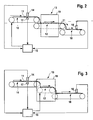
- Fig. 2:
- eine schematische Ansicht einer weiteren Trocknungsanlage;
- Fig. 3:
- eine schematische Ansicht einer dritten Trocknungsanlage; und
- Fig. 4:
- eine schematische Darstellung verschiedener Trockungsvorgänge.
- Fig. 1:
- a schematic view of a drying plant;
- Fig. 2:
- a schematic view of another drying plant;
- 3:
- a schematic view of a third drying plant; and
- 4:
- a schematic representation of various drying processes.
Das zu trocknende Tabakgut 11 wird mittels einer Zuführeinheit, die das Zuförderband 10 umfaßt, in Pfeilrichtung zugeführt. Am abschließenden Ende des Zuförderbandes wird das Gut 11 der Trocknungsvorrichtung 13 zugeführt. In der Trocknungsvorrichtung 13 bewirken nicht gezeigte Heizeinrichtungen eine Erwärmung des durch die Trocknungsvorrichtung 13 geführten Guts 11, um eine Verdampfung von in dem Gut 11 enthaltenem Wasser und somit eine Trocknung des Guts 11 zu bewirken. Das getrocknete Gut wird nach Verlassen der Trocknungsvorrichtung 13 mittels des weiteren Förderbandes 18 nachfolgenden Verarbeitungsstufen zugeführt.The
Bei der Trocknungsvorrichtung 13 aus Fig. 1 kann es sich beispielsweise um einen Stromtrockner, einen Trommeltrockner, einen Wirbelschichttrockner oder einen anderen dem Fachmann geläufigen Trockner handeln. Im Fall der Fig. 2 und 3 umfaßt die Trocknungsvorrichtung 13 eine Verdampfungskammer 19, wobei das Gut 11 mittels einer Transportvorrichtung, die hier als Förderband 12 ausgebildet ist, durch die Verdampfungskammer 19 geführt wird. Bei anderen Ausführungsformen kann das Gut von einem energieübertragenden Medium, beispielsweise heißem Gas, verwirbelt und/oder transportiert werden. Separate Fördereinrichtungen in der Trocknungsvorrichtung 13 sind daher nicht zwingend erforderlich.The drying
Mittels des Eingangsfeuchtesensors 14 wird die Eingangsfeuchte des Guts 11 bestimmt und ein entsprechendes Gutseingangsfeuchtesignal fe an die Steuerungseinrichtung 15 übermittelt. Mittels des Ausgangsfeuchtesensors 16 wird die Ausgangsfeuchte fa des Guts 11 bestimmt und ein entsprechendes Gutsausgangsfeuchtesignal an die Steuerungseinrichtung 15 übermittelt. Mittels der Waage 17 wird die Eingangsmasse me des Guts 11 bestimmt und ein entsprechendes Gutseingangsmassesignal an die Steuerungseinrichtung 15 übermittelt.The input moisture of the
Die Steuerungseinrichtung 15 steuert den durch die Trocknungsvorrichtung 13 geführten Gutsmassenstrom in Abhängigkeit mindestens eines der Meßsignale fe, fa, me mit dem Ziel, die Gutsausgangsfeuchte fa konstant zu halten. Zu diesem Zweck wird in den in Fig. 1 und 2 gezeigten Ausführungsbeispielen die Zuführvorrichtung angesteuert, um den der Trocknungsvorrichtung 13 zugeführten Gutseingangsmassenstrom zu regeln. Dies kann beispielsweise durch Steuerung der Fördergeschwindigkeit des Zuförderbandes 10 geschehen, wie in Fig. 1 und 2 gezeigt. Der einzustellende, durch die Trocknungsvorrichtung 13 zu führende Massenstrom m/Δt läßt sich näherungsweise durch folgende Beziehung ermitteln: ![]()
![]()
Dabei bezeichnet mV(H2O)/Δt die pro Zeiteinheit in der Trocknungsvorrichtung 13 verdampfte Wassermasse und fa * die gewünschte Ausgangsfeuchte (Sollwert). Wenn zweckmäßigerweise die Verdampfungsparameter, d.h. die Verdampfungstemperatur und die Heizleistung konstant gehalten werden, ist die pro Zeiteinheit in der Trocknungsvorrichtung 13 verdampfte Wassermenge mV(H2O)/Δt etwa konstant und näherungsweise nicht von der Menge bzw. Transportgeschwindigkeit des durch den Verdampfungsraum geführten Gutes abhängig. Durch Einsetzen der Meßgröße fe in obige Formel kann dann mittels der obigen Formel der einzustellende Massenstrom m/Δt durch die Trocknungsvorrichtung 13 ermittelt werden. Die Steuerung erfolgt in den Beispielen der Fig. 1 und 2 durch Veränderung der Zufördergeschwindigkeit des Zuförderbandes 10, bis das mittels der Waage gemessene Eingangsmassensignal me für das von der Waage erfaßte Transportintervall Δt mit dem mittels der obigen Formel bestimmten Sollwert übereinstimmt. In Fig. 1 und 2 wird daher der Massenstrom m/Δt durch die Trocknungsvorrichtung 13 durch entsprechende Veränderung des Gutseingangsmassenstroms me/Δt verändert.In this case, m V (H 2 O) / Δt denotes the mass of water evaporated per unit time in the drying
Bei der Waage 17 zur Messung des Eingangsmassesignals kann es sich beispielsweise um eine Bandwaage, beispielsweise als Einheit mit dem Zuförderband 10, handeln. Andere Ausführungsformen, beispielsweise eine Prallplattenwaage, sind möglich. Vorzugsweise ist die Integrationsstrecke der Waage 17, d.h. die in dem Meßvorgang erfaßte Meßstrecke, zur Verbesserung der Genauigkeit möglichst gering. Vorzugsweise sind aus denselben Gründen die Waage 17 und/oder der Eingangsfeuchtesensor 14 möglichst dicht an der Trocknungsvorrichtung 13 angeordnet, um eine möglichst zeitnahe Steuerung zu ermöglichen bzw. damit Veränderungen auf der Strecke zwischen dem jeweiligen Meßgerät und der Trocknungsvorrichtung 13 und sonstige vergleichbare Fehlerquellen einen möglichst geringen Einfluß haben.The
Die Messung beispielsweise der Eingangsfeuchte fe reicht grundsätzlich aus, um eine Steuerung des durch die Trocknungsvorrichtung 13 geführten Gutsmassenstroms in Abhängigkeit des entsprechenden Meßsignals zur Erzielung einer konstanten Ausgangsfeuchte vornehmen zu können. Vorzugsweise wird die Ausgangsfeuchte fa (Istwert) meßtechnisch ermittelt, um eine Korrektur bzw. einen Abgleich dieser Zielgröße mit der Sollgröße fa * vornehmen zu können. Dies kann beispielsweise durch Einfügung eines Korrekturfaktors fa */fa in die obige Formel erreicht werden. Hierdurch kann beispielsweise der für die Erwärmung des Tabaks erforderliche Energieverbrauch ausgeglichen werden.The measurement of, for example, the input moisture f e is basically sufficient to control the mass flow of material through the drying
Es kann anstelle der Eingangsfeuchte fe auch eine andere Meßgröße wie beispielsweise die Ausgangsfeuchte fa oder die Gutseingangsmasse me als Steuerungsgrundlage dienen; die Messung der Eingangsfeuchte ist dann nicht zwingend erforderlich.Instead of the input moisture f e, it is also possible to use another measured variable, such as, for example, the starting moisture f a or the input earth mass m e as the basis for the control; the measurement of the input moisture is then not mandatory.
Im Beispiel der Fig. 1 bis 3 kann auf eine meßtechnische Bestimmung der Gutseingangsmasse me auch verzichtet werden. In diesem Fall kann die einzustellende Zuführgeschwindigkeit entweder berechnet oder insbesondere mittels einer gespeicherten Kalibrierungskurve bestimmt werden. Es kann daher unter Umständen eine Kalibrierung der Zuführgeschwindigkeit für verschiedene Werte des entsprechenden Meßsignals erforderlich sein. Allgemein können nicht gemessene Größen beispielsweise berechnet oder mittels gespeicherter Kalibrierungskurven bestimmt werden. Es kann beispielsweise eine Kalibrierung des durch die Trocknungsvorrichtung 13 zu führenden Gutsmassenstroms für verschiedene Werte des entsprechenden Meßsignals erforderlich sein.In the example of Figs. 1 to 3 can be dispensed with a metrological determination of the Gutseingangsmasse m e . In this case, the feed rate to be set can either be calculated or in particular determined by means of a stored calibration curve. It may therefore be necessary to calibrate the feed rate for different values of the corresponding measurement signal. In general, unmeasured magnitudes can be calculated, for example, or determined using stored calibration curves. For example, it may be necessary to calibrate the bulk mass flow to be conducted by the drying
Im Ausführungsbeispiel der Fig. 3 wird die Transportgeschwindigkeit, mit der das Gut durch die Trocknungsvorrichtung 13 geführt wird, verändert. Dies geschieht beispielsweise durch Ansteuerung eines Kammerförderbandes 12, das wie in Fig. 3 gezeigt vollständig oder wie in Fig. 2 gezeigt teilweise in der Trocknungsvorrichtung 13 enthalten sein kann. Dies ist aber nicht zwingend erforderlich, die Steuerung kann auch ohne separate Fördereinrichtungen in der Trocknungsvorrichtung 13 erfolgen. Bei einer weiteren Ausführungsform kann beispielsweise in Fig. 2 die Förderbandgeschwindigkeit des Förderbandes 12 zur Steuerung des durch die Trocknungsvorrichtung 13 geförderten Gutsmassenstroms angesteuert werden.In the embodiment of Fig. 3, the transport speed at which the material is passed through the drying
Anstelle der drei in den Figuren 2 und 3 gezeigten Förderbänder 10, 12 und 18 kann auch ein einziges durchgehendes Förderband vorgesehen sein.Instead of the three
Anhand von Fig. 4 sei die Steuerung des durch die Trocknungsvorrichtung 13 geförderten Gutsmassenstroms anhand eines Beispiels erläutert. In Fig. 4A weist das der Trocknungsvorrichtung 13 zugeführte Gut 11 eine Eingangsfeuchte von 50 % auf. Dies wird zeichnerisch dadurch verdeutlicht, daß abwechselnd eine Trockengut-Masseeinheit (ein leeres Kästchen) und eine Wasser-Masseeinheit (ein schraffiertes Kästchen) gezeichnet sind. Der Einfachheit halber sei angenommen, daß ein Kästchen einer Masse von 1 kg entspricht. Die Verdampfungstemperatur, die Verdampfungsleistung und sonstige Verdampfungsparameter der Trocknungsvorrichtung 13 seien so eingestellt und werden so konstant gehalten, daß in der Trocknungsvorrichtung 13 pro Sekunde 2 kg Wasser verdampft werden. Es handelt sich dabei um eine Eigenschaft der Trocknungsvorrichtung 13 unabhängig von der Feuchte und Transportgeschwindigkeit des durch die Trocknungsvorrichtung 13 geführten Gutes. In Fig. 4A wird beispielsweise das feuchte Gut mit einem Eingangsmassenstrom von 6 kg/s zugeführt und durch die Trocknungsvorrichtung 13 geführt, wobei es sich aufgrund der eingestellten Transportgeschwindigkeit 1 s in der Trocknungsvorrichtung 13 aufhalten möge; dies führt zu einer Verdampfung von 2 kg Wasser, so daß die Ausgangsfeuchte des Gutes 25 % beträgt (1 kg Wasser auf 3 kg Trockengut, siehe Fig. 4A). Es sei angenommen, daß dies der gewünschten Ausgangsfeuchte entspricht.4, the control of the Gutsmassenstroms funded by the drying
Nun sei angenommen, daß sich die Eingangsfeuchte wie in Fig. 4B gezeigt aufgrund einer Eingangsfeuchteschwankung auf 40 % ändert (2 kg Wasser auf 3 kg Trockengut). Ohne weitere Maßnahmen würden dann bei ansonsten unveränderten Bedingungen 2 kg Wasser / s verdampft werden, so daß die Ausgangsfeuchte wie gezeigt etwa 0 % betragen würde. Mittels des Eingangsfeuchtesensors 14 wird eine Eingangsfeuchte fe von 40 % gemessen. Einsetzen dieses Wertes in die obige Formel mit mV(H2O)/Δt = 2 kg/s und fa* = 0.25 ergibt für den einzustellenden, durch den Verdampfungsraum zu fördernden Massenstrom m/Δt = mV(H2O)/Δt · [(1- fa *)/( fe - fa *)] = 10 kg/s. Die Steuerungseinrichtung 15 steuert daher den durch die Trocknungsvorrichtung 13 geführten Gutsmassenstrom auf 10 kg/s.Now suppose that the input moisture changes to 40% as shown in Fig. 4B due to an input moisture fluctuation (2 kg of water per 3 kg of dry matter). Without further measures, 2 kg of water / s would then be evaporated under otherwise unchanged conditions, so that the initial moisture would be about 0% as shown. By means of the
Dies kann auf unterschiedliche Weise erfolgen. Beispielsweise kann, wie in den Beispielen der Fig. 4C und 4E, der Eingangsmassenstrom von 5 kg/s auf 10 kg/s verdoppelt werden. Dies kann beispielsweise, wie im Beispiel der Fig. 4C, durch Verdoppelung der Zuführgeschwindigkeit erreicht werden, wie durch den Doppelpfeil angedeutet. Im Beispiel der Fig. 4C bleibt die Transportgeschwindigkeit durch die Trocknungsvorrichtung 13 unverändert im Vergleich zum vorigen, in Fig. 4B gezeigten Zustand. Da das Gut daher unverändert 1 s in der Trocknungsvorrichtung 13 verbleibt und dabei 2 kg Wasser verdampft werden, verläßt das Gut die Trocknungsvorrichtung 13 mit 8 kg/s und der gewünschten Feuchte von 25 % (s. Fig. 4C).This can be done in different ways. For example, as in the examples of Figs. 4C and 4E, the input mass flow can be doubled from 5 kg / s to 10 kg / s. This can be achieved, for example, as in the example of FIG. 4C, by doubling the feed rate, as indicated by the double arrow. In the example of FIG. 4C, the transport speed through the drying
Im Beispiel der Fig. 4E bleibt die Zuführgeschwindigkeit unverändert, jedoch wird die Massenbelegung des Zuförderbandes pro Bandstrecke verdoppelt. Das Ergebnis ist dasselbe wie in Fig. 4C gezeigt.In the example of FIG. 4E, the feed rate remains unchanged, but the mass occupancy of the feed conveyor per track is doubled. The result is the same as shown in Fig. 4C.
Im Beispiel der Fig. 4D bleibt der Eingangsmassenstrom unverändert, jedoch wird die Transportgeschwindigkeit durch die Trocknungsvorrichtung 13 verdoppelt. Nun verbleibt das Gut nur noch 1/2 Sekunde in der Trocknungsvorrichtung 13; in diesem Zeitraum wird nur 1 kg Wasser in der Trocknungsvorrichtung 13 verdampft. Im Ergebnis verläßt das Gut die Trocknungsvorrichtung 13 mit 4 kg/s und der gewünschten Feuchte von 25 % (s. Fig. 4D).In the example of FIG. 4D, the input mass flow remains unchanged, but the transport speed is doubled by the drying
Mischformen aller Art zwischen den Beispielen der Fig. 4C, 4D und 4E sind möglich. Beispielsweise könnte das Gut mit 8 kg/s zugefördert und mit einer um 25 % erhöhten Geschwindigkeit durch die Trocknungsvorrichtung 13 gefördert werden. Allerdings sind die Ausführungsformen, bei denen die Transportgeschwindigkeit durch die Trocknungsvorrichtung 13 jederzeit konstant bleibt (beispielsweise Fig. 4C, 4E), bevorzugt gegenüber den Ausführungsformen, für welche dies nicht zutrifft (beispielsweise Fig. 4D), da dies die Verwendung bekannter Verdampfungsvorrichtungen mit konstanter Transportgeschwindigkeit erlaubt.Mixed forms of all kinds between the examples of FIGS. 4C, 4D and 4E are possible. For example, the material could be conveyed at 8 kg / s and conveyed through the drying
Im Falle eines durchgehenden Förderbandes wäre eine Erhöhung der Förderbandgeschwindigkeit um den Faktor √2 (allgemein Faktor √n) zweckmäßig, um eine Verdoppelung (allgemein Erhöhung um den Faktor n) des durch die Trocknungsvorrichtung 13 geführten Gutsmassenstroms zu erzielen.In the case of a continuous conveyor belt an increase in the conveyor belt speed by a factor of √2 (generally factor √n) would be expedient to a doubling (Generally increase by the factor n) of the guided through the drying
Beispielsweise anhand des Vergleichs der Fig. 4A und 4B ist ersichtlich, daß sich der Gutseingangsmassenstrom bei schwankender Eingangsfeuchte entsprechend von alleine ändert. Davon zu unterscheiden ist die aktiv gesteuerte Veränderung des Gutseingangsmassenstroms mittels der Steuerungseinrichtung 15 beispielsweise wie in Fig. 4C und 4E gezeigt.For example, based on the comparison of FIGS. 4A and 4B, it can be seen that the input earth mass flow changes correspondingly with fluctuating input moisture. This is to be distinguished from the actively controlled change in the Gutseingangsassenstrom by means of the
Claims (12)
- Drying unit for drying a tobacco product (11) which comprises a drying apparatus (13) for drying the product (11) passed through the drying apparatus (13) and a measuring device for producing a measuring signal related to the input moisture of the product (11) before it is supplied to the drying apparatus (13), characterized in that the drying unit comprises a control device (15) for control of the product mass stream passed through the drying apparatus (13) as a function of the measuring signal, wherein variable control of the product mass stream is performed such that at higher input moisture, a lower product mass stream is passed through the drying apparatus and vice versa.
- Drying unit according to claim 1, characterized in that the drying unit is equipped to control the product mass stream supplied to the drying apparatus (13).
- Drying unit according to claim 1 or 2, characterized in that the drying unit is equipped to control the conveying speed of a product conveyer belt.
- Drying unit according to one of claims 1 to 3, characterized in that the measuring device is a moisture measuring device.
- Drying unit according to one of claims 1 to 4, characterized in that the drying unit comprises a moisture measuring device (14) to measure the input moisture of the product (11) before it is supplied to the drying apparatus (13).
- Drying unit according to one of claims 1 to 5, characterized in that the drying unit comprises a weighing means (17) to measure the input mass of the product (11) before it is supplied to the drying apparatus (13).
- Drying unit according to claim 6, characterized in that the drying unit is equipped to control the product mass stream passed through the drying apparatus (13) as a function of a measuring signal output by the weighing means (17).
- Drying unit according to claim 6 or 7, characterized in that the weighing means (17) is designed as a belt weigher.
- Drying unit according to one of claims 1 to 8, characterized in that the drying unit comprises an output moisture measuring device (16) to measure the output moisture of the product (11) after leaving the drying apparatus (13).
- Drying unit according to claim 9, characterized in that the drying unit is equipped to regulate the product mass stream passed through the drying device (13) as a function of a measuring signal output by the output moisture measuring device (16).
- Drying unit according to one of claims 1 to 10, characterized in that the product mass stream passed through the drying apparatus (13) is controlled in indirect proportion to the difference between the input moisture and the nominal value of the output moisture.
- Drying process for drying a tobacco product, comprising the supply of the product to a drying apparatus and drying of the product passed through the drying apparatus, characterized by the production of a measuring signal, related to the input moisture of the product before it is supplied to the drying apparatus, and variable control of the product mass stream supplied to the drying apparatus as a function of the measuring signal such that at higher input moisture, a lower product mass stream is passed through the drying apparatus and vice versa.
Priority Applications (1)
| Application Number | Priority Date | Filing Date | Title |
|---|---|---|---|
| EP04090361A EP1516544B1 (en) | 2003-09-19 | 2004-09-17 | Drying plant for tobacco and method for drying tobacco |
Applications Claiming Priority (3)
| Application Number | Priority Date | Filing Date | Title |
|---|---|---|---|
| EP03090308 | 2003-09-19 | ||
| EP03090308 | 2003-09-19 | ||
| EP04090361A EP1516544B1 (en) | 2003-09-19 | 2004-09-17 | Drying plant for tobacco and method for drying tobacco |
Publications (2)
| Publication Number | Publication Date |
|---|---|
| EP1516544A1 EP1516544A1 (en) | 2005-03-23 |
| EP1516544B1 true EP1516544B1 (en) | 2007-06-27 |
Family
ID=34196151
Family Applications (1)
| Application Number | Title | Priority Date | Filing Date |
|---|---|---|---|
| EP04090361A Expired - Lifetime EP1516544B1 (en) | 2003-09-19 | 2004-09-17 | Drying plant for tobacco and method for drying tobacco |
Country Status (1)
| Country | Link |
|---|---|
| EP (1) | EP1516544B1 (en) |
Cited By (2)
| Publication number | Priority date | Publication date | Assignee | Title |
|---|---|---|---|---|
| CN106403502A (en) * | 2016-09-28 | 2017-02-15 | 青岛科技大学 | Drying system for intelligently controlling rotation speed of motor through inlet temperature |
| CN106403563A (en) * | 2016-09-28 | 2017-02-15 | 青岛科技大学 | Drying system controlling coal supply amount intelligently according to outlet temperature |
Families Citing this family (2)
| Publication number | Priority date | Publication date | Assignee | Title |
|---|---|---|---|---|
| DE102005062857A1 (en) * | 2005-12-23 | 2007-06-28 | Hauni Maschinenbau Ag | Method and apparatus for drying a fiber product mass flow |
| CN106403501B (en) * | 2016-09-28 | 2019-03-26 | 青岛科技大学 | It is a kind of according to coal-supplying amount intelligent control to the drying system of intake |
Family Cites Families (5)
| Publication number | Priority date | Publication date | Assignee | Title |
|---|---|---|---|---|
| DE1206771B (en) * | 1963-11-18 | 1965-12-09 | Hauni Werke Koerber & Co Kg | Method and device for drying tobacco or similar goods |
| DE1532063A1 (en) * | 1965-07-06 | 1970-01-08 | Hauni Werke Koerber & Co Kg | Process and system for the balling of green balls |
| DE2019369C3 (en) * | 1970-04-22 | 1980-08-28 | Hauni-Werke Koerber & Co Kg, 2050 Hamburg | Method of drying tobacco and drying conveyor |
| SE373488B (en) * | 1973-06-07 | 1975-02-10 | Svenska Tobaks Ab | WAY TO POSSIBLE DETAILED DETERMINATION OR REGULATION OF A TREATMENT OF A PASSENGER MASS AND DEVICE FOR EXERCISING THE SET |
| JPS619275A (en) * | 1984-06-21 | 1986-01-16 | 日本たばこ産業株式会社 | Temperature control of tobacco leaf chopping dryer |
-
2004
- 2004-09-17 EP EP04090361A patent/EP1516544B1/en not_active Expired - Lifetime
Non-Patent Citations (1)
| Title |
|---|
| None * |
Cited By (3)
| Publication number | Priority date | Publication date | Assignee | Title |
|---|---|---|---|---|
| CN106403502A (en) * | 2016-09-28 | 2017-02-15 | 青岛科技大学 | Drying system for intelligently controlling rotation speed of motor through inlet temperature |
| CN106403563A (en) * | 2016-09-28 | 2017-02-15 | 青岛科技大学 | Drying system controlling coal supply amount intelligently according to outlet temperature |
| CN106403502B (en) * | 2016-09-28 | 2019-03-26 | 青岛科技大学 | A kind of drying system according to inlet temperature intelligent control motor revolving speed |
Also Published As
| Publication number | Publication date |
|---|---|
| EP1516544A1 (en) | 2005-03-23 |
Similar Documents
| Publication | Publication Date | Title |
|---|---|---|
| DE69417163T2 (en) | Method and device for quantifying a dough product | |
| EP0421165B1 (en) | Method for taring a conveyor-type dispensing scale | |
| EP0140213B1 (en) | Process and device for measuring the mass flow of fluent solid material | |
| DE2504902C2 (en) | Method and device for controlling the cutting capacity of a tobacco cutter | |
| CH668641A5 (en) | METHOD AND DEVICE FOR AUTOMATICALLY DETECTING THE THROUGHPUT OF A FLOW OF MATERIALS, e.g. GRAIN. | |
| DE2019369C3 (en) | Method of drying tobacco and drying conveyor | |
| DE2432848C2 (en) | Method and device for drying tobacco | |
| DE3037025C2 (en) | ||
| DE2747232A1 (en) | METHOD AND DEVICE FOR CARRYING OUT TREATMENT PROCEDURES FOR SCHUETTGUETER ETC. | |
| WO1986004417A1 (en) | Method and device for the determination of characteristic values, particularly of grain | |
| DE1532066C3 (en) | Arrangement for the continuous merging of different tobacco components | |
| DE1299237C2 (en) | METHOD AND DEVICE FOR DRYING TOBACCO | |
| EP1516544B1 (en) | Drying plant for tobacco and method for drying tobacco | |
| DE2461579C3 (en) | Method and device for the continuous supply of powdery goods from a storage container to a consumer | |
| DE2841470C2 (en) | ||
| DE2807691B1 (en) | Method and device for regulating the fineness of finished goods from a grinding plant | |
| DE102017119069A1 (en) | Method for filling containers with a filling product | |
| DE2427229C3 (en) | Method for controlling the treatment of a tobacco leaf mass and apparatus for practicing the method | |
| EP1129019B1 (en) | Method and device for the pneumatic transport of bulk goods | |
| EP0121599A2 (en) | Method and device for pneumatically transporting particulate matter | |
| DE1206771B (en) | Method and device for drying tobacco or similar goods | |
| DE1914466A1 (en) | Method and apparatus for removing tobacco from a compressed supply | |
| DE3212423A1 (en) | METHOD FOR PNEUMATICALLY DISCHARGING GOODS FROM A STORAGE CONTAINER | |
| DE19723218A1 (en) | Weighing bulk goods from silo | |
| DE2263722B2 (en) | METHOD AND APPARATUS FOR REGULATING THE ADDITION OF LIQUID TO A MACHINE FOR ROLLING BALLS TO BE SINTERED |
Legal Events
| Date | Code | Title | Description |
|---|---|---|---|
| PUAI | Public reference made under article 153(3) epc to a published international application that has entered the european phase |
Free format text: ORIGINAL CODE: 0009012 |
|
| AK | Designated contracting states |
Kind code of ref document: A1 Designated state(s): AT BE BG CH CY CZ DE DK EE ES FI FR GB GR HU IE IT LI LU MC NL PL PT RO SE SI SK TR |
|
| AX | Request for extension of the european patent |
Extension state: AL HR LT LV MK |
|
| 17P | Request for examination filed |
Effective date: 20050922 |
|
| AKX | Designation fees paid |
Designated state(s): AT BE BG CH CY CZ DE DK EE ES FI FR GB GR HU IE IT LI LU MC NL PL PT RO SE SI SK TR |
|
| GRAP | Despatch of communication of intention to grant a patent |
Free format text: ORIGINAL CODE: EPIDOSNIGR1 |
|
| GRAS | Grant fee paid |
Free format text: ORIGINAL CODE: EPIDOSNIGR3 |
|
| GRAA | (expected) grant |
Free format text: ORIGINAL CODE: 0009210 |
|
| AK | Designated contracting states |
Kind code of ref document: B1 Designated state(s): AT BE BG CH CY CZ DE DK EE ES FI FR GB GR HU IE IT LI LU MC NL PL PT RO SE SI SK TR |
|
| REG | Reference to a national code |
Ref country code: GB Ref legal event code: FG4D Free format text: NOT ENGLISH |
|
| REG | Reference to a national code |
Ref country code: CH Ref legal event code: EP |
|
| REG | Reference to a national code |
Ref country code: IE Ref legal event code: FG4D Free format text: LANGUAGE OF EP DOCUMENT: GERMAN |
|
| REF | Corresponds to: |
Ref document number: 502004004177 Country of ref document: DE Date of ref document: 20070809 Kind code of ref document: P |
|
| PG25 | Lapsed in a contracting state [announced via postgrant information from national office to epo] |
Ref country code: SE Free format text: LAPSE BECAUSE OF FAILURE TO SUBMIT A TRANSLATION OF THE DESCRIPTION OR TO PAY THE FEE WITHIN THE PRESCRIBED TIME-LIMIT Effective date: 20070927 |
|
| GBT | Gb: translation of ep patent filed (gb section 77(6)(a)/1977) |
Effective date: 20071004 |
|
| PG25 | Lapsed in a contracting state [announced via postgrant information from national office to epo] |
Ref country code: PL Free format text: LAPSE BECAUSE OF FAILURE TO SUBMIT A TRANSLATION OF THE DESCRIPTION OR TO PAY THE FEE WITHIN THE PRESCRIBED TIME-LIMIT Effective date: 20070627 |
|
| REG | Reference to a national code |
Ref country code: IE Ref legal event code: FD4D |
|
| PG25 | Lapsed in a contracting state [announced via postgrant information from national office to epo] |
Ref country code: CZ Free format text: LAPSE BECAUSE OF FAILURE TO SUBMIT A TRANSLATION OF THE DESCRIPTION OR TO PAY THE FEE WITHIN THE PRESCRIBED TIME-LIMIT Effective date: 20070627 Ref country code: ES Free format text: LAPSE BECAUSE OF FAILURE TO SUBMIT A TRANSLATION OF THE DESCRIPTION OR TO PAY THE FEE WITHIN THE PRESCRIBED TIME-LIMIT Effective date: 20071008 Ref country code: BG Free format text: LAPSE BECAUSE OF FAILURE TO SUBMIT A TRANSLATION OF THE DESCRIPTION OR TO PAY THE FEE WITHIN THE PRESCRIBED TIME-LIMIT Effective date: 20070927 Ref country code: IE Free format text: LAPSE BECAUSE OF FAILURE TO SUBMIT A TRANSLATION OF THE DESCRIPTION OR TO PAY THE FEE WITHIN THE PRESCRIBED TIME-LIMIT Effective date: 20070627 Ref country code: SI Free format text: LAPSE BECAUSE OF FAILURE TO SUBMIT A TRANSLATION OF THE DESCRIPTION OR TO PAY THE FEE WITHIN THE PRESCRIBED TIME-LIMIT Effective date: 20070627 Ref country code: PT Free format text: LAPSE BECAUSE OF FAILURE TO SUBMIT A TRANSLATION OF THE DESCRIPTION OR TO PAY THE FEE WITHIN THE PRESCRIBED TIME-LIMIT Effective date: 20071127 |
|
| EN | Fr: translation not filed | ||
| PG25 | Lapsed in a contracting state [announced via postgrant information from national office to epo] |
Ref country code: SK Free format text: LAPSE BECAUSE OF FAILURE TO SUBMIT A TRANSLATION OF THE DESCRIPTION OR TO PAY THE FEE WITHIN THE PRESCRIBED TIME-LIMIT Effective date: 20070627 |
|
| PLBI | Opposition filed |
Free format text: ORIGINAL CODE: 0009260 |
|
| BERE | Be: lapsed |
Owner name: HAUNI MASCHINENBAU A.G. Effective date: 20070930 |
|
| PLAX | Notice of opposition and request to file observation + time limit sent |
Free format text: ORIGINAL CODE: EPIDOSNOBS2 |
|
| 26 | Opposition filed |
Opponent name: PHILIP MORRIS PRODUCTS S.A. Effective date: 20080320 |
|
| PG25 | Lapsed in a contracting state [announced via postgrant information from national office to epo] |
Ref country code: DK Free format text: LAPSE BECAUSE OF FAILURE TO SUBMIT A TRANSLATION OF THE DESCRIPTION OR TO PAY THE FEE WITHIN THE PRESCRIBED TIME-LIMIT Effective date: 20070627 Ref country code: GR Free format text: LAPSE BECAUSE OF FAILURE TO SUBMIT A TRANSLATION OF THE DESCRIPTION OR TO PAY THE FEE WITHIN THE PRESCRIBED TIME-LIMIT Effective date: 20070928 Ref country code: MC Free format text: LAPSE BECAUSE OF NON-PAYMENT OF DUE FEES Effective date: 20070930 |
|
| PG25 | Lapsed in a contracting state [announced via postgrant information from national office to epo] |
Ref country code: RO Free format text: LAPSE BECAUSE OF FAILURE TO SUBMIT A TRANSLATION OF THE DESCRIPTION OR TO PAY THE FEE WITHIN THE PRESCRIBED TIME-LIMIT Effective date: 20070627 |
|
| NLR1 | Nl: opposition has been filed with the epo |
Opponent name: PHILIP MORRIS PRODUCTS S.A. |
|
| PLBB | Reply of patent proprietor to notice(s) of opposition received |
Free format text: ORIGINAL CODE: EPIDOSNOBS3 |
|
| PG25 | Lapsed in a contracting state [announced via postgrant information from national office to epo] |
Ref country code: FR Free format text: LAPSE BECAUSE OF FAILURE TO SUBMIT A TRANSLATION OF THE DESCRIPTION OR TO PAY THE FEE WITHIN THE PRESCRIBED TIME-LIMIT Effective date: 20080222 |
|
| PG25 | Lapsed in a contracting state [announced via postgrant information from national office to epo] |
Ref country code: BE Free format text: LAPSE BECAUSE OF NON-PAYMENT OF DUE FEES Effective date: 20070930 |
|
| PG25 | Lapsed in a contracting state [announced via postgrant information from national office to epo] |
Ref country code: AT Free format text: LAPSE BECAUSE OF NON-PAYMENT OF DUE FEES Effective date: 20070917 |
|
| PGFP | Annual fee paid to national office [announced via postgrant information from national office to epo] |
Ref country code: IT Payment date: 20080924 Year of fee payment: 5 Ref country code: NL Payment date: 20080930 Year of fee payment: 5 |
|
| PGFP | Annual fee paid to national office [announced via postgrant information from national office to epo] |
Ref country code: GB Payment date: 20080924 Year of fee payment: 5 |
|
| PG25 | Lapsed in a contracting state [announced via postgrant information from national office to epo] |
Ref country code: EE Free format text: LAPSE BECAUSE OF FAILURE TO SUBMIT A TRANSLATION OF THE DESCRIPTION OR TO PAY THE FEE WITHIN THE PRESCRIBED TIME-LIMIT Effective date: 20070627 |
|
| PGFP | Annual fee paid to national office [announced via postgrant information from national office to epo] |
Ref country code: DE Payment date: 20080930 Year of fee payment: 5 |
|
| PG25 | Lapsed in a contracting state [announced via postgrant information from national office to epo] |
Ref country code: FI Free format text: LAPSE BECAUSE OF FAILURE TO SUBMIT A TRANSLATION OF THE DESCRIPTION OR TO PAY THE FEE WITHIN THE PRESCRIBED TIME-LIMIT Effective date: 20070627 |
|
| REG | Reference to a national code |
Ref country code: CH Ref legal event code: PL |
|
| PG25 | Lapsed in a contracting state [announced via postgrant information from national office to epo] |
Ref country code: CH Free format text: LAPSE BECAUSE OF NON-PAYMENT OF DUE FEES Effective date: 20070930 Ref country code: LI Free format text: LAPSE BECAUSE OF NON-PAYMENT OF DUE FEES Effective date: 20070930 |
|
| PG25 | Lapsed in a contracting state [announced via postgrant information from national office to epo] |
Ref country code: CY Free format text: LAPSE BECAUSE OF FAILURE TO SUBMIT A TRANSLATION OF THE DESCRIPTION OR TO PAY THE FEE WITHIN THE PRESCRIBED TIME-LIMIT Effective date: 20070627 |
|
| PG25 | Lapsed in a contracting state [announced via postgrant information from national office to epo] |
Ref country code: LU Free format text: LAPSE BECAUSE OF NON-PAYMENT OF DUE FEES Effective date: 20070917 |
|
| PG25 | Lapsed in a contracting state [announced via postgrant information from national office to epo] |
Ref country code: TR Free format text: LAPSE BECAUSE OF FAILURE TO SUBMIT A TRANSLATION OF THE DESCRIPTION OR TO PAY THE FEE WITHIN THE PRESCRIBED TIME-LIMIT Effective date: 20070627 Ref country code: HU Free format text: LAPSE BECAUSE OF FAILURE TO SUBMIT A TRANSLATION OF THE DESCRIPTION OR TO PAY THE FEE WITHIN THE PRESCRIBED TIME-LIMIT Effective date: 20071228 |
|
| PG25 | Lapsed in a contracting state [announced via postgrant information from national office to epo] |
Ref country code: LI Free format text: LAPSE BECAUSE OF NON-PAYMENT OF DUE FEES Effective date: 20080930 Ref country code: CH Free format text: LAPSE BECAUSE OF NON-PAYMENT OF DUE FEES Effective date: 20080930 |
|
| GBPC | Gb: european patent ceased through non-payment of renewal fee |
Effective date: 20090917 |
|
| REG | Reference to a national code |
Ref country code: NL Ref legal event code: V1 Effective date: 20100401 |
|
| PG25 | Lapsed in a contracting state [announced via postgrant information from national office to epo] |
Ref country code: DE Free format text: LAPSE BECAUSE OF NON-PAYMENT OF DUE FEES Effective date: 20100401 |
|
| PG25 | Lapsed in a contracting state [announced via postgrant information from national office to epo] |
Ref country code: NL Free format text: LAPSE BECAUSE OF NON-PAYMENT OF DUE FEES Effective date: 20100401 |
|
| PG25 | Lapsed in a contracting state [announced via postgrant information from national office to epo] |
Ref country code: GB Free format text: LAPSE BECAUSE OF NON-PAYMENT OF DUE FEES Effective date: 20090917 |
|
| PG25 | Lapsed in a contracting state [announced via postgrant information from national office to epo] |
Ref country code: IT Free format text: LAPSE BECAUSE OF NON-PAYMENT OF DUE FEES Effective date: 20090917 |
|
| PLBD | Termination of opposition procedure: decision despatched |
Free format text: ORIGINAL CODE: EPIDOSNOPC1 |
|
| PLBM | Termination of opposition procedure: date of legal effect published |
Free format text: ORIGINAL CODE: 0009276 |
|
| STAA | Information on the status of an ep patent application or granted ep patent |
Free format text: STATUS: OPPOSITION PROCEDURE CLOSED |
|
| 27C | Opposition proceedings terminated |
Effective date: 20110527 |