EP1516159B1 - Temperaturkompensation einer sensoranordnung (gmr) mit beidseitigen potential nderungen - Google Patents
Temperaturkompensation einer sensoranordnung (gmr) mit beidseitigen potential nderungen Download PDFInfo
- Publication number
- EP1516159B1 EP1516159B1 EP03760584A EP03760584A EP1516159B1 EP 1516159 B1 EP1516159 B1 EP 1516159B1 EP 03760584 A EP03760584 A EP 03760584A EP 03760584 A EP03760584 A EP 03760584A EP 1516159 B1 EP1516159 B1 EP 1516159B1
- Authority
- EP
- European Patent Office
- Prior art keywords
- potential
- input
- sensor arrangement
- temperature
- bridge circuit
- Prior art date
- Legal status (The legal status is an assumption and is not a legal conclusion. Google has not performed a legal analysis and makes no representation as to the accuracy of the status listed.)
- Expired - Lifetime
Links
Images


Classifications
-
- G—PHYSICS
- G01—MEASURING; TESTING
- G01D—MEASURING NOT SPECIALLY ADAPTED FOR A SPECIFIC VARIABLE; ARRANGEMENTS FOR MEASURING TWO OR MORE VARIABLES NOT COVERED IN A SINGLE OTHER SUBCLASS; TARIFF METERING APPARATUS; MEASURING OR TESTING NOT OTHERWISE PROVIDED FOR
- G01D5/00—Mechanical means for transferring the output of a sensing member; Means for converting the output of a sensing member to another variable where the form or nature of the sensing member does not constrain the means for converting; Transducers not specially adapted for a specific variable
- G01D5/12—Mechanical means for transferring the output of a sensing member; Means for converting the output of a sensing member to another variable where the form or nature of the sensing member does not constrain the means for converting; Transducers not specially adapted for a specific variable using electric or magnetic means
- G01D5/14—Mechanical means for transferring the output of a sensing member; Means for converting the output of a sensing member to another variable where the form or nature of the sensing member does not constrain the means for converting; Transducers not specially adapted for a specific variable using electric or magnetic means influencing the magnitude of a current or voltage
- G01D5/142—Mechanical means for transferring the output of a sensing member; Means for converting the output of a sensing member to another variable where the form or nature of the sensing member does not constrain the means for converting; Transducers not specially adapted for a specific variable using electric or magnetic means influencing the magnitude of a current or voltage using Hall-effect devices
- G01D5/145—Mechanical means for transferring the output of a sensing member; Means for converting the output of a sensing member to another variable where the form or nature of the sensing member does not constrain the means for converting; Transducers not specially adapted for a specific variable using electric or magnetic means influencing the magnitude of a current or voltage using Hall-effect devices influenced by the relative movement between the Hall device and magnetic fields
-
- B—PERFORMING OPERATIONS; TRANSPORTING
- B82—NANOTECHNOLOGY
- B82Y—SPECIFIC USES OR APPLICATIONS OF NANOSTRUCTURES; MEASUREMENT OR ANALYSIS OF NANOSTRUCTURES; MANUFACTURE OR TREATMENT OF NANOSTRUCTURES
- B82Y25/00—Nanomagnetism, e.g. magnetoimpedance, anisotropic magnetoresistance, giant magnetoresistance or tunneling magnetoresistance
-
- G—PHYSICS
- G01—MEASURING; TESTING
- G01D—MEASURING NOT SPECIALLY ADAPTED FOR A SPECIFIC VARIABLE; ARRANGEMENTS FOR MEASURING TWO OR MORE VARIABLES NOT COVERED IN A SINGLE OTHER SUBCLASS; TARIFF METERING APPARATUS; MEASURING OR TESTING NOT OTHERWISE PROVIDED FOR
- G01D5/00—Mechanical means for transferring the output of a sensing member; Means for converting the output of a sensing member to another variable where the form or nature of the sensing member does not constrain the means for converting; Transducers not specially adapted for a specific variable
- G01D5/12—Mechanical means for transferring the output of a sensing member; Means for converting the output of a sensing member to another variable where the form or nature of the sensing member does not constrain the means for converting; Transducers not specially adapted for a specific variable using electric or magnetic means
- G01D5/244—Mechanical means for transferring the output of a sensing member; Means for converting the output of a sensing member to another variable where the form or nature of the sensing member does not constrain the means for converting; Transducers not specially adapted for a specific variable using electric or magnetic means influencing characteristics of pulses or pulse trains; generating pulses or pulse trains
- G01D5/24428—Error prevention
-
- G—PHYSICS
- G01—MEASURING; TESTING
- G01D—MEASURING NOT SPECIALLY ADAPTED FOR A SPECIFIC VARIABLE; ARRANGEMENTS FOR MEASURING TWO OR MORE VARIABLES NOT COVERED IN A SINGLE OTHER SUBCLASS; TARIFF METERING APPARATUS; MEASURING OR TESTING NOT OTHERWISE PROVIDED FOR
- G01D5/00—Mechanical means for transferring the output of a sensing member; Means for converting the output of a sensing member to another variable where the form or nature of the sensing member does not constrain the means for converting; Transducers not specially adapted for a specific variable
- G01D5/12—Mechanical means for transferring the output of a sensing member; Means for converting the output of a sensing member to another variable where the form or nature of the sensing member does not constrain the means for converting; Transducers not specially adapted for a specific variable using electric or magnetic means
- G01D5/244—Mechanical means for transferring the output of a sensing member; Means for converting the output of a sensing member to another variable where the form or nature of the sensing member does not constrain the means for converting; Transducers not specially adapted for a specific variable using electric or magnetic means influencing characteristics of pulses or pulse trains; generating pulses or pulse trains
- G01D5/24428—Error prevention
- G01D5/24433—Error prevention by mechanical means
- G01D5/24438—Special design of the sensing element or scale
-
- G—PHYSICS
- G01—MEASURING; TESTING
- G01D—MEASURING NOT SPECIALLY ADAPTED FOR A SPECIFIC VARIABLE; ARRANGEMENTS FOR MEASURING TWO OR MORE VARIABLES NOT COVERED IN A SINGLE OTHER SUBCLASS; TARIFF METERING APPARATUS; MEASURING OR TESTING NOT OTHERWISE PROVIDED FOR
- G01D5/00—Mechanical means for transferring the output of a sensing member; Means for converting the output of a sensing member to another variable where the form or nature of the sensing member does not constrain the means for converting; Transducers not specially adapted for a specific variable
- G01D5/12—Mechanical means for transferring the output of a sensing member; Means for converting the output of a sensing member to another variable where the form or nature of the sensing member does not constrain the means for converting; Transducers not specially adapted for a specific variable using electric or magnetic means
- G01D5/244—Mechanical means for transferring the output of a sensing member; Means for converting the output of a sensing member to another variable where the form or nature of the sensing member does not constrain the means for converting; Transducers not specially adapted for a specific variable using electric or magnetic means influencing characteristics of pulses or pulse trains; generating pulses or pulse trains
- G01D5/24471—Error correction
- G01D5/2448—Correction of gain, threshold, offset or phase control
-
- G—PHYSICS
- G01—MEASURING; TESTING
- G01R—MEASURING ELECTRIC VARIABLES; MEASURING MAGNETIC VARIABLES
- G01R33/00—Arrangements or instruments for measuring magnetic variables
- G01R33/02—Measuring direction or magnitude of magnetic fields or magnetic flux
- G01R33/06—Measuring direction or magnitude of magnetic fields or magnetic flux using galvano-magnetic devices
- G01R33/09—Magnetoresistive devices
- G01R33/093—Magnetoresistive devices using multilayer structures, e.g. giant magnetoresistance sensors
Definitions
- the invention relates to a method for temperature compensation of a Sensor arrangement. It further relates to a temperature-compensated Sensor arrangement with a bridge circuit.
- Such a sensor arrangement delivers at least one output signal during operation, which depends on a quantity to be measured, e.g. from the brightness of one Light source, from the direction of a magnetic field, etc.
- Under one Bridge circuit is understood here as a half or full bridge.
- the Bridge connects the potential at its first input in a first Senses is changing, and that the potential at their second input in a for first sense opposite second sense changes.
- This can e.g. mean that at a certain temperature rise, the potential at the first input is 0.1 V increases, and the potential at the second input decreases by 0.1 V, the Changes preferably are sized so that the output signal is practical remains unchanged, as long as the size to be measured does not change.
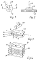
- Fig. 1 shows a two-pole magnetic disk 20 which rotates in operation in the direction of arrow 22 and over which a sensor 39 is arranged.
- GMR Giant Magneto Resistor
- FIGS. 3 and 4 serve to explain a GMR sensor which is preferably used in the present invention.
- Magnetic field sensors in the manner of Hall sensors are very well suited for contactless measurements, ie position detection, distance, speed and speed measurements, measurements of the direction of rotation, as well as measurements of Streams and achievements.
- Hall sensors allow even under difficult Conditions (dew, dirt, extreme temperatures, etc.) accurate measurements.
- GMR sensors Since conventional Hall sensors react to the strength of the magnetic field, they are very sensitive to fluctuations in the distance between the sensor and the magnet. In In some cases, however, one would like to receive a signal that is reliable only from the direction, but not dependent on the strength of a magnetic field.
- the GMR sensors were designed specifically for positional applications developed because they only the direction of the magnetic field lines, but not the intensity Measure the magnetic flux, resulting in relatively large measuring distances up to 25 mm allows. This facilitates the assembly of these sensors and their adjustment, and makes mass production cheaper. Another advantage is the size the GMR sensors. For the type GMR_C6, as described below underlying embodiment, this sensor is located in a 6 pin package measuring only 2.9 x 1.3 x 1.1 mm.
- Fig. 3 shows the basic principle of an element 24 of a GMR sensor.
- This element 24 has two soft ferromagnetic cover layers 26, 28, in which an adjacent permanent magnet 30 generates a magnetic flux M with a direction phi (FIG. 4), which depends on the instantaneous rotational position of this permanent magnet 30.
- a layer stack 32 with fixed Magnetization Between the cover layers 26, 28 is a layer stack 32 with fixed Magnetization. As is apparent from Fig. 4, several alternate in the layer stack 32 Co layers of cobalt and Cu of copper. The thickness of each layer is extremely low and is in the range of a few nanometers. The non-magnetic Copper separates the iron and cobalt layers as shown. By the very thin separating layers, the cobalt layers become an artificial one Coupled "antiferromagnets". The hard ferromagnetic cobalt layers are Co magnetized in the manner shown in Fig. 4 alternately fixed.
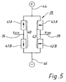
- Fig. 5 shows the basic structure of a GMR_C6 bridge 39, which has two half-bridges 40, 42.
- the half-bridge 40 contains two sensor elements 41 A, 41 B whose connection point is designated 36 and whose preferred directions of flow are indicated.
- the half-bridge 42 contains two sensor elements 43A, 43B whose connection point is denoted by 38 and whose preferred directions of flow extend in the manner indicated at a right angle to those of the sensor elements 41A, 41B. Therefore, such an arrangement is referred to as "crossed half-bridges" 40, 42.
- Data sheet 8 mV can be, if between the connections 44 or 46 of the sensor 39, an operating voltage of 7 V is applied.
- GMR sensors have a temperature-dependent output signal. With increasing temperature increases the total resistance of the bridge circuit, whereby the signal at the output 36 and the signal at the output 38 decreases. Therefore should with increasing temperature, the voltage between the inputs 44 and 46 can be increased, if for a given angle phi the voltages wants to keep constant at the outputs 36 and 38 regardless of the temperature.
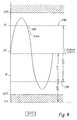
- Fig. 6 shows in simplified and highly schematized form basic considerations in the present invention.
- the magnetic field of the rotating Magnetic disk 20 is sampled, and it arises at the output 36 of the sensor 39th a sinusoidal voltage 50 whose positive maximum is e.g. an angle phi of the external magnetic field M of 90 °, the negative maximum of an angle phi of 270 ° and their value zero corresponds to an angle phi of 0 °, 180 ° or 360 °.
- the voltage is 50 Temperature dependent, and therefore takes place in an arrangement 52 a Temperature compensation, by which this voltage is independent of the instantaneous temperature of the sensor 39 is made, and there is a Coordinate shift into a voltage range in the illustrated Example, between + 0.3 V and + 3.5 V, where the zero line, which a Angle phi of 0 °, 180 ° or 360 ° corresponds to + 1.9V.
- the Coordinate-shifted voltage is indicated at 54 in FIG. naturally the given numbers are only exemplary values, which the understanding of the To facilitate invention but in no way limit the invention.
- the voltage 54 which in this example is preferably within the range 0.3V should be up to 3.5V, e.g. subsequently through an A / D converter 56 digitized and then further processed, e.g. as shown in a DSP processor 58.
- a DSP processor 58 additional Signal corrections done, so that at its output 60 is an optimized Signal in digitized form can provide that in quality to the signal corresponds to a resolver and very exactly the direction phi of the magnetic field M am GMR sensor 39).
- Fig. 7 shows a preferred embodiment of an inventive Sensor arrangement. Same or equivalent parts as in the previous ones Figures are denoted by the same reference numerals as there and usually not described again.
- the GMR sensor 39 again symbolically the magnetic disk 20 shown.
- the registered Potentials are measured values that occur at an ambient temperature of 25 ° C were measured.
- a first arrangement 68th intended for feeding the first input 44 of the sensor 39. This has a voltage divider with two fixed resistors 70, 72 and a PTC resistor 74 having a resistance of 2 k ⁇ at 25 ° C.
- this potential does not inverting input of an impedance converter 78 supplied to the output thereof 80 is also the potential of 3V.
- This output 80 is over a Line 81 with the first input 44 of the sensor 39 and with the inverting Input 82 of the amplifier 78 is connected.
- the potential p 76 increases as the temperature increases because the resistance of the PTC resistor 74 increases with temperature, preferably linearly.
- a second arrangement 86 is provided.
- This contains one Operational amplifier 88, whose output 90 to the second input 46 of Sensor 39 is connected.
- the output 90 is connected through a resistor 92 to the inverting input 94 connected in turn via a resistor 96 with the output 80 is connected.
- a gain factor of -1 is set for the inverting input 94, and the temperature-dependent potential p 80 from the output 80 is supplied to this input via the resistor 96.
- the operating voltage of 2.2 V is symmetrical to an offset voltage of 1.9 V.
- first input 44 and the second input 46 are two identical resistors 106, 108 of e.g. 10 k ⁇ each, and on her Connection point 110 can tapped this offset voltage and as a DC reference value be used for subsequent amplifiers.
- the output signals of the sensor 39 at the outputs 36 and 38 have e.g. if they have a sinusoidal course, each having a signal swing of 50 mV, which is symmetrical to the offset voltage of 1.9V. This makes it possible for the To increase alternating component of these two signals.
- the potential p 90 drops to 0.5 V, and the potential p 80 rises to 3.3 V.
- the circuit of FIG. 7 thus has the property that in the Temperature compensation, the offset voltage remains unchanged and at this preferred example has a value of 1.9 V, which is in the middle of a desired Voltage range of 0.3V to 3.5V provided by the D / A converters 56, 56 '. maximum can be processed. So it finds a coordinate transformation instead of, i. the horizontal axis (time axis) of the coordinate system becomes 1.9 V moved in a positive direction.
- the output signals at the two outputs 36, 38 have the sensor type GMR_C6, which is operated at 25 ° C with an operating voltage of 2.2 V, a signal swing (peak to peak voltage) of approx. 50 mV. Suitable for the Subsequent processing is a signal swing of about 3V, i. you need one Reinforcement by a factor of 60.
- a resistor 128 is the inverting input 130 of the amplifier 120, the signal supplied from the output 36.
- a resistor 132 is the Input 130 connected to the output 134, to which the A / D converter 56th connected.
- the amplified sinusoidal voltage (with 3 V signal swing) symmetrical to this potential of 1.9 V, i. it has a minimum value of 0.4 V and a maximum value of 3.4 V, as shown schematically in Fig. 8.
- this tension is within of the digitization favorable range 0.3 ... 3.5 V, giving a secure Signal processing possible and a small safety distance in both directions is available.
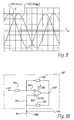
- Fig. 9 shows by way of illustration the amplified output voltages at the outputs 134, 144.
- two sinusoidal voltages 150, 152 which are phase-shifted by 90 ° relative to one another, are produced at these outputs.
- the amplitude of these signals is substantially constant in the range between -20 ° C and + 100 ° C, so that the images for these two temperatures are virtually indistinguishable.
- the offset by 1.9 V is not shown in Fig. 9.
- FIG. 10 shows a variant 68 'designated as NIC for the arrangement 68 of FIG. 7. Since the remaining parts of the circuit are unchanged, only the deviating part 68' is shown and described.
- This variant 68 has an operational amplifier 160 whose inverting input 162 is connected via a resistor 164 to a regulated voltage, here +5 V. Furthermore, the input 162 is connected via a resistor 166 to the output 168 of the amplifier 160, which in turn is connected via a resistor 170 to the non-inverting input 172, the terminal 44 of the GMR 39, and the line 81, ie receives at the terminal 44 one has the same potential p 80 as in FIG. 7.
- the GMR sensor 39 has a resistance Ro of 700 at 25 ° C Ohm between his connections 44 and 46. Ro has an influence on the potential at the input 172. Since the operational amplifier 160 the potential difference between its inputs162, 172 regulates to 0 V, the potentials are at the Entrances 162, 172 same.
Landscapes
- Physics & Mathematics (AREA)
- General Physics & Mathematics (AREA)
- Chemical & Material Sciences (AREA)
- Engineering & Computer Science (AREA)
- Nanotechnology (AREA)
- Condensed Matter Physics & Semiconductors (AREA)
- Crystallography & Structural Chemistry (AREA)
- Measuring Magnetic Variables (AREA)
- Transmission And Conversion Of Sensor Element Output (AREA)
Description
- Fig. 1
- eine zweipolige Magnetscheibe 20, die im Betrieb in Richtung eines Pfeiles 22 rotiert und über der ein sogenannter GMR-Sensor 39 angeordnet ist, mit dem die Richtung phi eines von der Scheibe 20 im Sensor 39 erzeugten magnetischen Flusses M erfasst wird,
- Fig. 2
- einen Schnitt, gesehen längs der Linie II-II der Fig. 1, welcher zeigt, dass der GMR-Sensor 39 im Abstand von der Scheibe 20 angeordnet ist,
- Fig. 3
- ein schematische Darstellung zur Erläuterung der Wirkungsweise eines Elements eines GMR-Sensors,
- Fig. 4
- eine schematische Darstellung des inneren Aufbaus eines Elements eines GMR-Sensors,
- Fig. 5
- eine Darstellung von zwei Halbbrücken 40, 42 eines GMR-Sensors einer bestimmten Bauart,
- Fig. 6
- eine stark schematisierte Ubersichtsdarstellung zur Erläuterung der Grundzüge der Erfindung,
- Fig. 7
- ein Schaltbild gemäß einer bevorzugten Ausführungsform der Erfindung,
- Fig. 8
- eine schematische Darstellung zur Erläuterung von Fig. 7,
- Fig. 9
- ein Oszillogramm von zwei Messspannungen, die von einem temperaturkompensierten GMR-Sensor geliefert werden, und
- Fig. 10
- eine Variante zu Fig. 7 mit einem NIC (Negative Impedance Converter).
Sein invertierender Verstärker hat eine Verstärkung von
| Operationsverstärker 78, 88, 120, 122 | LM2904/MC |
| Sensor 39 | GMR_C6 |
| PTC-Widerstand 74 | KTY_13_6 |
| R 70 | 3,3 kΩ |
| R 72 | 3 kΩ |
| R 92, 96, 106, 108 | 10 kΩ |
| R 100 | 18 kΩ |
| R 102 | 11 kΩ |
| R 128, 138 | 2 kΩ |
| R 132, 142 | 120 kΩ |
Claims (12)
- Verfahren zur Temperaturkompensation einer Sensoranordnung (39), welche eine Halb- oder Vollbrückenanordnung aufweist, in der mindestens ein Element (41A, 41B, 43A, 43B) von einer messenden Größe (ϕ) abhängig ist, um ein von dieser zu messenden Größe abhängiges Ausgangssignal zu erhalten,
wobei die Sensoranordnung (39) zur Zuführung einer Speisespannung einen ersten Anschluss (44) und einen zweiten Anschluss (46) aufweist, mit folgenden Schritten:wobei letzterer etwa so eingestellt wird, dass er im wesentlichen einem mittleren Wert der zulässigen analogen Eingangswerte mindestens eines der Sensoranordnung nachgeschalteten A/D-Wandlers (56; 56') entspricht.a) Wenn sich die Temperatur der Sensoranordnung (39) in einer vorgegebenen Richtung ändert, wird das erste Potenzial (p80) am ersten Anschluss (44) in einem ersten Sinne geändert;b) das zweite Potenzial (p90) am zweiten Anschluss (46) wird in diesem Fall in einem zum ersten Sinne entgegengesetzten Sinne geändert;c) bezogen auf ein periodisches Ausgangssignal, das einen vorgegebenen Mittelwert (110) aufweist, wird, bezogen auf diesen Mittelwert, die Änderung des ersten Potenzials im wesentlichen um denselben Betrag vorgenommen wie die Änderung des zweiten Potenzials, um eine Temperaturkompensation durch eine Änderung der Speisespannung der Sensoranordnung (39) zu erreichen, welche im wesentlichen symmetrisch zu diesem Mittelwert (110) erfolgt, - Verfahren nach Anspruch 1, bei welchem das Ausgangssignal (Fig. 6: 50) der Sensoranordnung (39) einer Koordinatenverschiebung (Fig. 6: 52) unterzogen wird.
- Verfahren nach Anspruch 1 oder 2, bei welchem die Sensoranordnung (39) eine Mehrzahl von temperaturabhängigen Widerständen (41A, 41B, 43A, 43B) aufweist, deren Widerstandswerte temperaturabhängig sind und die als Vollbrückenschaltung (39) geschaltet sind.
- Sensoranordnung mit einer als Halb- oder Vollbrückenschaltung ausgebildeten Brückenschaltung (40, 42),
welche ein temperaturabhängiges Betriebsverhalten aufweist,
welche zu ihrer Speisung mit einer Betriebsspannung einen ersten' Eingang (44) und einen zweiten Eingang (46) aufweist,
und welche mindestens einen Ausgang (36, 38) hat, an dem im Betrieb ein von einer zu messenden Größe (phi) abhängiges Ausgangssignal (Vsin, Vcos) auftritt,
mit einer ersten Anordnung (68; 68') zum Erzeugen eines temperaturabhängigen ersten Potenzials (p80), welches das Temperaturverhalten der Brückenschaltung (40, 42) im wesentlichen nachahmt und zum Speisen des ersten Eingangs (44) der Brückenschaltung (40, 42) dient,
und mit einer zweiten Anordnung (86), welche dazu dient, ausgehend von einem im wesentlichen konstanten zweiten Gleichspannungspotenzial (p98) dadurch ein drittes Gleichspannungspotenzial (p90) für den zweiten Eingang (46) der Brückenschaltung (40, 42) zu bilden, dass im wesentlichen von einem mit einem vorgegebenen Faktor multiplizierten Wert des zweiten Gleichspannungspotenzials (p98) das temperaturabhängige erste Gleichspannungspotenzial (p80) subtrahiert wird, um so den beiden Eingängen (44, 46) der Brückenschaltung (40, 42) eine temperaturabhängige Speisespannung zuzuführen, welche das mindestens eine Ausgangssignal (Vsin, Vcos) der Brückenschaltung (40, 42) bei einem konstanten Wert der zu messenden Größe (phi) innerhalb eines vorgegebenen Temperaturbereichs im wesentlichen konstant hält,
wobei der Mittelwert der Speisespannung etwa so eingestellt ist, dass er im wesentlichen einem mittleren Wert der zulässigen analogen Eingangswerte mindestens eines der Sensoranordnung nachgeschalteten A/D-Wandlers (56; 56') entspricht. - Sensoranordnung nach Anspruch 4, bei welcher die erste Anordnung (68) einen ersten Spannungsteiler (70, 72, 74) aufweist, welcher mindestens einen temperaturabhängigen Widerstand (74) aufweist.
- Sensoranordnung nach Anspruch 5, bei welcher ein am ersten Spannungsteiler angeschlossener Verstärker (78) vorgesehen ist, dessen Ausgangspotenzial (p80) zur Speisung des ersten Eingangs (44) der Brückenschaltung (40, 42) dient.
- Sensoranordnung nach einem der Ansprüche 4 bis 6, bei welcher zur Erzeugung des dritten Potenzials (p90) ein Operationsverstärker (88) vorgesehen ist, der einen Verstärkungsfaktor von im wesentlichen 1 aufweist,
dessen nicht invertierendem Eingang (98) das im wesentlichen konstante zweite Gleichspannungspotenzial (p98) zugeführt wird,
und dessen invertierendem Eingang (94) das temperaturabhängige erste Gleichspannungspotenzial (p80) zugeführt wird. - Sensoranordnung nach einem der Ansprüche 4 bis 7, bei welcher das im wesentlichen konstante zweite Gleichspannungspotenzial (p98) einer vorgegebenen Offsetspannung entspricht.
- Sensoranordnung nach einem der Ansprüche 4 bis 8, bei welcher ein vorgegebenes Offselpotenzial gebildet wird, welches im Bereich zwischen dem Potenzial (p80) am ersten Eingang (44) und dem Potenzial (p90) am zweiten Eingang (46) der Brückenschaltung (40, 42) liegt,
und bei welchem das mindestens eine Ausgangssignal (Vsin, Vcos) der Brückenschaltung (40, 42) einem Eingang (130; 140) eines Operationsverstärkers (120; 122) zugeführt wird, dessen anderer Eingang (124; 126) an diesem Offsetpotenzial liegt. - Sensoranordnung nach Anspruch 9, bei welcher das Offsetpotenzial im wesentlichen in der Mitte zwischen dem Potenzial (p80) am ersten Eingang (44) und dem Potenzial (p90) am zweiten Eingang (46) der Brückenschaltung (40, 42) liegt.
- Sensoranordnung nach Anspruch 9 oder 10, bei welcher die Brückenschaltung (40, 42) zwei Ausgangssignale (Vsin, Vcos) aufweist, jedem dieser beiden Ausgangssignale zu seiner Verstärkung ein Operationsverstärker (120, 122) zugeordnet ist,
das betreffende Ausgangssignal (Vsin, Vcos) einem Eingang des zugeordneten Operationsverstärkers zugeführt wird,
und dem anderen Eingang des zugeordneten Operationsverstärkers das genannte Offsetpotanzial zugeführt wird. - Sensoranordnung nach einem der Ansprüche 4 bis 11, bei welcher die Brückenschaltung (40, 42) mit temperaturabhängigem Betriebsverhalten als Teil eines GMR-Sensors (39) ausgebildet ist.
Applications Claiming Priority (3)
| Application Number | Priority Date | Filing Date | Title |
|---|---|---|---|
| DE10228023 | 2002-06-24 | ||
| DE10228023 | 2002-06-24 | ||
| PCT/EP2003/004436 WO2004001341A1 (de) | 2002-06-24 | 2003-04-29 | Temperaturkompensation einer sensoranordnung (gmr) mit beidseitigen potentialänderungen |
Publications (2)
| Publication Number | Publication Date |
|---|---|
| EP1516159A1 EP1516159A1 (de) | 2005-03-23 |
| EP1516159B1 true EP1516159B1 (de) | 2005-11-30 |
Family
ID=29761331
Family Applications (1)
| Application Number | Title | Priority Date | Filing Date |
|---|---|---|---|
| EP03760584A Expired - Lifetime EP1516159B1 (de) | 2002-06-24 | 2003-04-29 | Temperaturkompensation einer sensoranordnung (gmr) mit beidseitigen potential nderungen |
Country Status (4)
| Country | Link |
|---|---|
| EP (1) | EP1516159B1 (de) |
| AU (1) | AU2003232216A1 (de) |
| DE (2) | DE50301815D1 (de) |
| WO (1) | WO2004001341A1 (de) |
Cited By (2)
| Publication number | Priority date | Publication date | Assignee | Title |
|---|---|---|---|---|
| US7965004B2 (en) | 2005-12-01 | 2011-06-21 | EBM—Papst St. Georgen GmbH & Co. KG | Electric motor |
| US9804006B2 (en) | 2014-03-31 | 2017-10-31 | Azbil Corporation | Angle sensor temperature correcting device |
Families Citing this family (5)
| Publication number | Priority date | Publication date | Assignee | Title |
|---|---|---|---|---|
| US7437135B2 (en) | 2003-10-30 | 2008-10-14 | Interdigital Technology Corporation | Joint channel equalizer interference canceller advanced receiver |
| US7400692B2 (en) | 2004-01-14 | 2008-07-15 | Interdigital Technology Corporation | Telescoping window based equalization |
| DE102004009267B3 (de) * | 2004-02-26 | 2005-09-22 | Siemens Ag | Ausleseeinrichtung wenigstens eines magnetoresistiven Elementes |
| DE102004016425B4 (de) * | 2004-04-02 | 2014-03-20 | Sick Ag | Schaltungsanordnung |
| ATE450780T1 (de) | 2005-07-26 | 2009-12-15 | Ebm Papst St Georgen Gmbh & Co | Elektromotor mit einem absolutwert- drehwinkelsensor, und verfahren zur erzeugung eines drehwinkel-absolutwerts |
Citations (2)
| Publication number | Priority date | Publication date | Assignee | Title |
|---|---|---|---|---|
| US5253532A (en) * | 1992-03-09 | 1993-10-19 | Timex Corporation | Temperature compensated pressure transducer with digital output for low voltage power supply |
| DE19531386A1 (de) * | 1995-08-26 | 1997-02-27 | Grau Gmbh | Auswerteschaltung für einen Dickfilm-Drucksensor |
Family Cites Families (4)
| Publication number | Priority date | Publication date | Assignee | Title |
|---|---|---|---|---|
| US4202218A (en) * | 1977-09-28 | 1980-05-13 | International Telephone And Telegraph Corporation | Bridge circuit |
| JPS5896202U (ja) * | 1981-12-23 | 1983-06-30 | 株式会社石田衡器製作所 | 歪みゲ−ジの温度補償回路 |
| DE19619806A1 (de) * | 1996-05-15 | 1997-11-20 | Siemens Ag | Magnetfeldempfindliche Sensoreinrichtung mit mehreren GMR-Sensorelementen |
| EP1178326B1 (de) * | 2000-07-05 | 2005-12-21 | Infineon Technologies AG | Verfahren und System zur Bestimmung der Orientierung von Magnetfeldern mit GMR-Sensoren |
-
2003
- 2003-04-29 AU AU2003232216A patent/AU2003232216A1/en not_active Abandoned
- 2003-04-29 EP EP03760584A patent/EP1516159B1/de not_active Expired - Lifetime
- 2003-04-29 DE DE50301815T patent/DE50301815D1/de not_active Expired - Lifetime
- 2003-04-29 WO PCT/EP2003/004436 patent/WO2004001341A1/de not_active Ceased
- 2003-06-14 DE DE2003126900 patent/DE10326900A1/de not_active Withdrawn
Patent Citations (2)
| Publication number | Priority date | Publication date | Assignee | Title |
|---|---|---|---|---|
| US5253532A (en) * | 1992-03-09 | 1993-10-19 | Timex Corporation | Temperature compensated pressure transducer with digital output for low voltage power supply |
| DE19531386A1 (de) * | 1995-08-26 | 1997-02-27 | Grau Gmbh | Auswerteschaltung für einen Dickfilm-Drucksensor |
Cited By (2)
| Publication number | Priority date | Publication date | Assignee | Title |
|---|---|---|---|---|
| US7965004B2 (en) | 2005-12-01 | 2011-06-21 | EBM—Papst St. Georgen GmbH & Co. KG | Electric motor |
| US9804006B2 (en) | 2014-03-31 | 2017-10-31 | Azbil Corporation | Angle sensor temperature correcting device |
Also Published As
| Publication number | Publication date |
|---|---|
| DE50301815D1 (de) | 2006-01-05 |
| DE10326900A1 (de) | 2004-01-22 |
| EP1516159A1 (de) | 2005-03-23 |
| AU2003232216A1 (en) | 2004-01-06 |
| WO2004001341A1 (de) | 2003-12-31 |
Similar Documents
| Publication | Publication Date | Title |
|---|---|---|
| EP0740776B1 (de) | Anordnung zur berührungslosen drehwinkelerfassung eines drehbaren elements | |
| EP0997706B1 (de) | Anordnung zur Messung einer relativen linearen Position | |
| DE19732616C2 (de) | Magnetfeld-Messgerät zur Messung der Drehung eines sich drehenden Körpers | |
| EP2396666B1 (de) | Anordnung zur messung mindestens einer komponente eines magnetfeldes | |
| DE19729808C2 (de) | Sensoreinrichtung | |
| DE102012100194B4 (de) | Drehwinkelsensor | |
| DE4343686B4 (de) | Magnetometer | |
| DE10342260B4 (de) | Magnetoresistiver Sensor in Form einer Halb- oder Vollbrückenschaltung | |
| DE102014103587B4 (de) | Magnetsensorsystem | |
| DE69324465T2 (de) | Magnetoresistive sensorschaltung mit hohem ausgangsspannungshub und temperaturkompensation | |
| DE19539722A1 (de) | Magnetowiderstandstyp-Sensorvorrichtung zum Erfassen einer Änderung eines Magnetfeldes | |
| EP0807827A2 (de) | Magnetfeldempfindliche Sensoreinrichtung mit mehreren GMR-Sensorelementen | |
| EP1046047B1 (de) | Magnetoresistives sensorelement mit wahlweiser magnetisierungsausrichtung der biasschicht | |
| DE19817356A1 (de) | Winkelgeber und Verfahren zur Winkelbestimmung | |
| EP1527324B1 (de) | Magnetoresistiver sensor | |
| DE19642752B4 (de) | Meßgerät zur Feststellung der Änderung eines Magnetfeldes | |
| DE19612422C2 (de) | Potentiometereinrichtung mit einem linear verschiebbaren Stellelement und signalerzeugenden Mitteln | |
| DE19647420B4 (de) | Vorrichtung zum Erfassen eines Magnetfelds | |
| DE10138908A1 (de) | Magnetische Erfassungsvorrichtung | |
| EP0201682B1 (de) | Integrierter Drehzahlsensor mit magnetfeldabhängigen Sensorwiderständen | |
| EP1516159A1 (de) | Temperaturkompensation einer sensoranordnung (gmr) mit beidseitigen potential nderungen | |
| WO2013174542A1 (de) | Magnetische differenzfeldsensoranordnung | |
| DE10257253A1 (de) | GMR-Sensorelement und dessen Verwendung | |
| DE102021133302A1 (de) | Magnetsensorvorrichtung, wechselrichtergerät und batteriegerät | |
| DE102020126871A1 (de) | Ein Sensorsystem, ein System und ein Verfahren zum Bestimmen einer Position oder eines Drehwinkels |
Legal Events
| Date | Code | Title | Description |
|---|---|---|---|
| PUAI | Public reference made under article 153(3) epc to a published international application that has entered the european phase |
Free format text: ORIGINAL CODE: 0009012 |
|
| 17P | Request for examination filed |
Effective date: 20040310 |
|
| AK | Designated contracting states |
Kind code of ref document: A1 Designated state(s): AT BE BG CH CY CZ DE DK EE ES FI FR GB GR HU IE IT LI LU MC NL PT RO SE SI SK TR |
|
| AX | Request for extension of the european patent |
Extension state: AL LT LV MK |
|
| RIN1 | Information on inventor provided before grant (corrected) |
Inventor name: PFAFF, ANDREAS Inventor name: RUDEL, CHRISTIAN |
|
| 17Q | First examination report despatched |
Effective date: 20050321 |
|
| GRAP | Despatch of communication of intention to grant a patent |
Free format text: ORIGINAL CODE: EPIDOSNIGR1 |
|
| RBV | Designated contracting states (corrected) |
Designated state(s): DE FR GB IT |
|
| GRAS | Grant fee paid |
Free format text: ORIGINAL CODE: EPIDOSNIGR3 |
|
| GRAA | (expected) grant |
Free format text: ORIGINAL CODE: 0009210 |
|
| AK | Designated contracting states |
Kind code of ref document: B1 Designated state(s): DE FR GB IT |
|
| REG | Reference to a national code |
Ref country code: GB Ref legal event code: FG4D Free format text: NOT ENGLISH |
|
| REF | Corresponds to: |
Ref document number: 50301815 Country of ref document: DE Date of ref document: 20060105 Kind code of ref document: P |
|
| GBT | Gb: translation of ep patent filed (gb section 77(6)(a)/1977) |
Effective date: 20060123 |
|
| ET | Fr: translation filed | ||
| PLBE | No opposition filed within time limit |
Free format text: ORIGINAL CODE: 0009261 |
|
| STAA | Information on the status of an ep patent application or granted ep patent |
Free format text: STATUS: NO OPPOSITION FILED WITHIN TIME LIMIT |
|
| 26N | No opposition filed |
Effective date: 20060831 |
|
| PGFP | Annual fee paid to national office [announced via postgrant information from national office to epo] |
Ref country code: FR Payment date: 20100317 Year of fee payment: 8 Ref country code: IT Payment date: 20091229 Year of fee payment: 8 |
|
| PGFP | Annual fee paid to national office [announced via postgrant information from national office to epo] |
Ref country code: GB Payment date: 20100323 Year of fee payment: 8 |
|
| PGFP | Annual fee paid to national office [announced via postgrant information from national office to epo] |
Ref country code: DE Payment date: 20100401 Year of fee payment: 8 |
|
| GBPC | Gb: european patent ceased through non-payment of renewal fee |
Effective date: 20110429 |
|
| REG | Reference to a national code |
Ref country code: FR Ref legal event code: ST Effective date: 20111230 |
|
| PG25 | Lapsed in a contracting state [announced via postgrant information from national office to epo] |
Ref country code: DE Free format text: LAPSE BECAUSE OF NON-PAYMENT OF DUE FEES Effective date: 20111101 Ref country code: FR Free format text: LAPSE BECAUSE OF NON-PAYMENT OF DUE FEES Effective date: 20110502 |
|
| REG | Reference to a national code |
Ref country code: DE Ref legal event code: R119 Ref document number: 50301815 Country of ref document: DE Effective date: 20111101 |
|
| PG25 | Lapsed in a contracting state [announced via postgrant information from national office to epo] |
Ref country code: GB Free format text: LAPSE BECAUSE OF NON-PAYMENT OF DUE FEES Effective date: 20110429 Ref country code: IT Free format text: LAPSE BECAUSE OF NON-PAYMENT OF DUE FEES Effective date: 20110429 |