EP1516074B1 - Creep resistant magnesium alloy - Google Patents
Creep resistant magnesium alloy Download PDFInfo
- Publication number
- EP1516074B1 EP1516074B1 EP03760532A EP03760532A EP1516074B1 EP 1516074 B1 EP1516074 B1 EP 1516074B1 EP 03760532 A EP03760532 A EP 03760532A EP 03760532 A EP03760532 A EP 03760532A EP 1516074 B1 EP1516074 B1 EP 1516074B1
- Authority
- EP
- European Patent Office
- Prior art keywords
- alloy
- magnesium
- neodymium
- weight
- rare earth
- Prior art date
- Legal status (The legal status is an assumption and is not a legal conclusion. Google has not performed a legal analysis and makes no representation as to the accuracy of the status listed.)
- Expired - Lifetime
Links
- 229910000861 Mg alloy Inorganic materials 0.000 title claims description 21
- 229910045601 alloy Inorganic materials 0.000 claims abstract description 75
- 239000000956 alloy Substances 0.000 claims abstract description 75
- 239000011701 zinc Substances 0.000 claims abstract description 35
- 229910052761 rare earth metal Inorganic materials 0.000 claims abstract description 32
- 229910052779 Neodymium Inorganic materials 0.000 claims abstract description 30
- QEFYFXOXNSNQGX-UHFFFAOYSA-N neodymium atom Chemical compound [Nd] QEFYFXOXNSNQGX-UHFFFAOYSA-N 0.000 claims abstract description 28
- 239000011777 magnesium Substances 0.000 claims abstract description 27
- 229910052749 magnesium Inorganic materials 0.000 claims abstract description 23
- FYYHWMGAXLPEAU-UHFFFAOYSA-N Magnesium Chemical compound [Mg] FYYHWMGAXLPEAU-UHFFFAOYSA-N 0.000 claims abstract description 22
- 229910052726 zirconium Inorganic materials 0.000 claims abstract description 20
- QCWXUUIWCKQGHC-UHFFFAOYSA-N Zirconium Chemical compound [Zr] QCWXUUIWCKQGHC-UHFFFAOYSA-N 0.000 claims abstract description 18
- 229910052725 zinc Inorganic materials 0.000 claims abstract description 18
- HCHKCACWOHOZIP-UHFFFAOYSA-N Zinc Chemical compound [Zn] HCHKCACWOHOZIP-UHFFFAOYSA-N 0.000 claims abstract description 15
- 239000012535 impurity Substances 0.000 claims abstract description 6
- WPBNNNQJVZRUHP-UHFFFAOYSA-L manganese(2+);methyl n-[[2-(methoxycarbonylcarbamothioylamino)phenyl]carbamothioyl]carbamate;n-[2-(sulfidocarbothioylamino)ethyl]carbamodithioate Chemical compound [Mn+2].[S-]C(=S)NCCNC([S-])=S.COC(=O)NC(=S)NC1=CC=CC=C1NC(=S)NC(=O)OC WPBNNNQJVZRUHP-UHFFFAOYSA-L 0.000 claims abstract description 4
- 230000003647 oxidation Effects 0.000 claims abstract description 4
- 238000007254 oxidation reaction Methods 0.000 claims abstract description 4
- 230000002401 inhibitory effect Effects 0.000 claims abstract 3
- 150000002910 rare earth metals Chemical class 0.000 claims description 22
- 238000000034 method Methods 0.000 claims description 19
- XEEYBQQBJWHFJM-UHFFFAOYSA-N Iron Chemical compound [Fe] XEEYBQQBJWHFJM-UHFFFAOYSA-N 0.000 claims description 17
- 238000005266 casting Methods 0.000 claims description 17
- 238000010438 heat treatment Methods 0.000 claims description 17
- PXHVJJICTQNCMI-UHFFFAOYSA-N Nickel Chemical compound [Ni] PXHVJJICTQNCMI-UHFFFAOYSA-N 0.000 claims description 11
- 239000002244 precipitate Substances 0.000 claims description 11
- 229910052684 Cerium Inorganic materials 0.000 claims description 8
- 229910052742 iron Inorganic materials 0.000 claims description 8
- 229910052727 yttrium Inorganic materials 0.000 claims description 8
- VWQVUPCCIRVNHF-UHFFFAOYSA-N yttrium atom Chemical compound [Y] VWQVUPCCIRVNHF-UHFFFAOYSA-N 0.000 claims description 8
- ZSLUVFAKFWKJRC-IGMARMGPSA-N 232Th Chemical compound [232Th] ZSLUVFAKFWKJRC-IGMARMGPSA-N 0.000 claims description 7
- 229910052776 Thorium Inorganic materials 0.000 claims description 7
- GWXLDORMOJMVQZ-UHFFFAOYSA-N cerium Chemical compound [Ce] GWXLDORMOJMVQZ-UHFFFAOYSA-N 0.000 claims description 7
- 239000010949 copper Substances 0.000 claims description 7
- 229910052709 silver Inorganic materials 0.000 claims description 7
- 239000004332 silver Substances 0.000 claims description 7
- RYGMFSIKBFXOCR-UHFFFAOYSA-N Copper Chemical compound [Cu] RYGMFSIKBFXOCR-UHFFFAOYSA-N 0.000 claims description 6
- 239000004411 aluminium Substances 0.000 claims description 6
- 229910052782 aluminium Inorganic materials 0.000 claims description 6
- XAGFODPZIPBFFR-UHFFFAOYSA-N aluminium Chemical compound [Al] XAGFODPZIPBFFR-UHFFFAOYSA-N 0.000 claims description 6
- 229910052802 copper Inorganic materials 0.000 claims description 6
- 238000010791 quenching Methods 0.000 claims description 6
- RTAQQCXQSZGOHL-UHFFFAOYSA-N Titanium Chemical compound [Ti] RTAQQCXQSZGOHL-UHFFFAOYSA-N 0.000 claims description 5
- 230000032683 aging Effects 0.000 claims description 5
- 229910052735 hafnium Inorganic materials 0.000 claims description 5
- VBJZVLUMGGDVMO-UHFFFAOYSA-N hafnium atom Chemical compound [Hf] VBJZVLUMGGDVMO-UHFFFAOYSA-N 0.000 claims description 5
- 229910052759 nickel Inorganic materials 0.000 claims description 5
- 229910052710 silicon Inorganic materials 0.000 claims description 5
- 239000010703 silicon Substances 0.000 claims description 5
- 239000010936 titanium Substances 0.000 claims description 5
- 229910052719 titanium Inorganic materials 0.000 claims description 5
- 230000000171 quenching effect Effects 0.000 claims description 4
- 239000006104 solid solution Substances 0.000 claims description 4
- 238000002485 combustion reaction Methods 0.000 claims description 3
- 238000002844 melting Methods 0.000 claims description 3
- 230000008018 melting Effects 0.000 claims description 3
- 239000004576 sand Substances 0.000 claims description 3
- 229910052712 strontium Inorganic materials 0.000 claims description 3
- CIOAGBVUUVVLOB-UHFFFAOYSA-N strontium atom Chemical compound [Sr] CIOAGBVUUVVLOB-UHFFFAOYSA-N 0.000 claims description 3
- 238000009827 uniform distribution Methods 0.000 claims description 2
- 239000000203 mixture Substances 0.000 description 55
- 230000000052 comparative effect Effects 0.000 description 23
- 238000012360 testing method Methods 0.000 description 22
- 230000035882 stress Effects 0.000 description 14
- 230000007797 corrosion Effects 0.000 description 9
- 238000005260 corrosion Methods 0.000 description 9
- XLYOFNOQVPJJNP-UHFFFAOYSA-N water Substances O XLYOFNOQVPJJNP-UHFFFAOYSA-N 0.000 description 9
- 230000014759 maintenance of location Effects 0.000 description 8
- 229910052746 lanthanum Inorganic materials 0.000 description 7
- 239000000243 solution Substances 0.000 description 7
- BQCADISMDOOEFD-UHFFFAOYSA-N Silver Chemical compound [Ag] BQCADISMDOOEFD-UHFFFAOYSA-N 0.000 description 6
- FZLIPJUXYLNCLC-UHFFFAOYSA-N lanthanum atom Chemical compound [La] FZLIPJUXYLNCLC-UHFFFAOYSA-N 0.000 description 6
- 229910001122 Mischmetal Inorganic materials 0.000 description 5
- FAPWRFPIFSIZLT-UHFFFAOYSA-M Sodium chloride Chemical compound [Na+].[Cl-] FAPWRFPIFSIZLT-UHFFFAOYSA-M 0.000 description 5
- 238000007792 addition Methods 0.000 description 5
- 238000004519 manufacturing process Methods 0.000 description 5
- 239000000463 material Substances 0.000 description 5
- 238000007528 sand casting Methods 0.000 description 5
- 238000005275 alloying Methods 0.000 description 4
- 238000013461 design Methods 0.000 description 4
- 239000011780 sodium chloride Substances 0.000 description 4
- 229910000838 Al alloy Inorganic materials 0.000 description 3
- LYCAIKOWRPUZTN-UHFFFAOYSA-N Ethylene glycol Chemical compound OCCO LYCAIKOWRPUZTN-UHFFFAOYSA-N 0.000 description 3
- VYPSYNLAJGMNEJ-UHFFFAOYSA-N Silicium dioxide Chemical compound O=[Si]=O VYPSYNLAJGMNEJ-UHFFFAOYSA-N 0.000 description 3
- HEMHJVSKTPXQMS-UHFFFAOYSA-M Sodium hydroxide Chemical compound [OH-].[Na+] HEMHJVSKTPXQMS-UHFFFAOYSA-M 0.000 description 3
- 238000007906 compression Methods 0.000 description 3
- 230000000694 effects Effects 0.000 description 3
- 230000005484 gravity Effects 0.000 description 3
- 238000011282 treatment Methods 0.000 description 3
- LFQSCWFLJHTTHZ-UHFFFAOYSA-N Ethanol Chemical compound CCO LFQSCWFLJHTTHZ-UHFFFAOYSA-N 0.000 description 2
- 230000006835 compression Effects 0.000 description 2
- 238000004320 controlled atmosphere Methods 0.000 description 2
- 239000002826 coolant Substances 0.000 description 2
- 230000007423 decrease Effects 0.000 description 2
- 230000002939 deleterious effect Effects 0.000 description 2
- 239000000446 fuel Substances 0.000 description 2
- 238000007654 immersion Methods 0.000 description 2
- 238000011068 loading method Methods 0.000 description 2
- 238000001000 micrograph Methods 0.000 description 2
- 238000002360 preparation method Methods 0.000 description 2
- 230000008569 process Effects 0.000 description 2
- 230000009467 reduction Effects 0.000 description 2
- 230000004044 response Effects 0.000 description 2
- 229910001060 Gray iron Inorganic materials 0.000 description 1
- 229910052765 Lutetium Inorganic materials 0.000 description 1
- PWHULOQIROXLJO-UHFFFAOYSA-N Manganese Chemical compound [Mn] PWHULOQIROXLJO-UHFFFAOYSA-N 0.000 description 1
- GRYLNZFGIOXLOG-UHFFFAOYSA-N Nitric acid Chemical compound O[N+]([O-])=O GRYLNZFGIOXLOG-UHFFFAOYSA-N 0.000 description 1
- 229910052777 Praseodymium Inorganic materials 0.000 description 1
- 229910001297 Zn alloy Inorganic materials 0.000 description 1
- GANNOFFDYMSBSZ-UHFFFAOYSA-N [AlH3].[Mg] Chemical compound [AlH3].[Mg] GANNOFFDYMSBSZ-UHFFFAOYSA-N 0.000 description 1
- 229910002056 binary alloy Inorganic materials 0.000 description 1
- 230000000903 blocking effect Effects 0.000 description 1
- 229910052799 carbon Inorganic materials 0.000 description 1
- 230000008859 change Effects 0.000 description 1
- KRVSOGSZCMJSLX-UHFFFAOYSA-L chromic acid Substances O[Cr](O)(=O)=O KRVSOGSZCMJSLX-UHFFFAOYSA-L 0.000 description 1
- 239000008119 colloidal silica Substances 0.000 description 1
- 239000002131 composite material Substances 0.000 description 1
- 150000001875 compounds Chemical class 0.000 description 1
- 238000010276 construction Methods 0.000 description 1
- 125000004122 cyclic group Chemical group 0.000 description 1
- 230000003247 decreasing effect Effects 0.000 description 1
- 230000001627 detrimental effect Effects 0.000 description 1
- 238000011161 development Methods 0.000 description 1
- 230000018109 developmental process Effects 0.000 description 1
- 229910003460 diamond Inorganic materials 0.000 description 1
- 239000010432 diamond Substances 0.000 description 1
- 238000004512 die casting Methods 0.000 description 1
- 238000009792 diffusion process Methods 0.000 description 1
- 238000009826 distribution Methods 0.000 description 1
- 238000005530 etching Methods 0.000 description 1
- 238000002474 experimental method Methods 0.000 description 1
- AWJWCTOOIBYHON-UHFFFAOYSA-N furo[3,4-b]pyrazine-5,7-dione Chemical compound C1=CN=C2C(=O)OC(=O)C2=N1 AWJWCTOOIBYHON-UHFFFAOYSA-N 0.000 description 1
- 238000007542 hardness measurement Methods 0.000 description 1
- 230000003993 interaction Effects 0.000 description 1
- 238000011835 investigation Methods 0.000 description 1
- 238000005495 investment casting Methods 0.000 description 1
- 239000007788 liquid Substances 0.000 description 1
- 230000007774 longterm Effects 0.000 description 1
- OHSVLFRHMCKCQY-UHFFFAOYSA-N lutetium atom Chemical compound [Lu] OHSVLFRHMCKCQY-UHFFFAOYSA-N 0.000 description 1
- 150000002680 magnesium Chemical class 0.000 description 1
- 229910052748 manganese Inorganic materials 0.000 description 1
- 239000011572 manganese Substances 0.000 description 1
- 239000000155 melt Substances 0.000 description 1
- 229910052751 metal Inorganic materials 0.000 description 1
- 239000002184 metal Substances 0.000 description 1
- 229910017604 nitric acid Inorganic materials 0.000 description 1
- 239000002245 particle Substances 0.000 description 1
- PUDIUYLPXJFUGB-UHFFFAOYSA-N praseodymium atom Chemical compound [Pr] PUDIUYLPXJFUGB-UHFFFAOYSA-N 0.000 description 1
- 230000001376 precipitating effect Effects 0.000 description 1
- 238000012545 processing Methods 0.000 description 1
- 239000000047 product Substances 0.000 description 1
- VSZWPYCFIRKVQL-UHFFFAOYSA-N selanylidenegallium;selenium Chemical compound [Se].[Se]=[Ga].[Se]=[Ga] VSZWPYCFIRKVQL-UHFFFAOYSA-N 0.000 description 1
- 229920002545 silicone oil Polymers 0.000 description 1
- 238000005728 strengthening Methods 0.000 description 1
- 239000002344 surface layer Substances 0.000 description 1
- JBQYATWDVHIOAR-UHFFFAOYSA-N tellanylidenegermanium Chemical compound [Te]=[Ge] JBQYATWDVHIOAR-UHFFFAOYSA-N 0.000 description 1
- 238000009864 tensile test Methods 0.000 description 1
- 238000010998 test method Methods 0.000 description 1
- 230000004580 weight loss Effects 0.000 description 1
Images


Classifications
-
- C—CHEMISTRY; METALLURGY
- C22—METALLURGY; FERROUS OR NON-FERROUS ALLOYS; TREATMENT OF ALLOYS OR NON-FERROUS METALS
- C22F—CHANGING THE PHYSICAL STRUCTURE OF NON-FERROUS METALS AND NON-FERROUS ALLOYS
- C22F1/00—Changing the physical structure of non-ferrous metals or alloys by heat treatment or by hot or cold working
- C22F1/06—Changing the physical structure of non-ferrous metals or alloys by heat treatment or by hot or cold working of magnesium or alloys based thereon
-
- C—CHEMISTRY; METALLURGY
- C22—METALLURGY; FERROUS OR NON-FERROUS ALLOYS; TREATMENT OF ALLOYS OR NON-FERROUS METALS
- C22C—ALLOYS
- C22C23/00—Alloys based on magnesium
- C22C23/06—Alloys based on magnesium with a rare earth metal as the next major constituent
Definitions
- the present invention relates to magnesium (Mg) alloys and, more particularly, to magnesium alloys which are resistant to creep at high temperatures.
- Magnesium alloys have been used for many years in applications where the material of construction is required to exhibit a high strength to weight ratio. Typically a component made from a magnesium alloy could be expected to have a weight about 70% of an aluminium (Al) alloy component of similar volume.
- Al aluminium
- the aerospace industry has accordingly been a significant user of magnesium alloys and magnesium alloys are used for many components in modern defence aircraft and spacecraft.
- one limitation preventing wider use of magnesium alloys is that, when compared to aluminium alloys, they typically have poorer resistance to creep at elevated temperatures.
- HPDC high pressure die casting
- the magnesium alloy ML10 developed in the USSR, has been used for many years for cast parts intended for use in aircraft at temperatures up to 250°C.
- ML10 is a high strength magnesium alloy developed on the basis of the Mg-Nd-Zn-Zr system.
- ML19 alloy additionally contains yttrium.
- the document GB-A-1 378 281 discloses a magnesium based alloy consisting of, in weight %: 0.8 to 6.0% yttrium, 0.5 to 4.0% neodymium 0.1 to 2.2% zinc, 0.31 to 1.1 % zirconium, up to 0.05% copper, up to 0.2% manganese, the balance being magnesium.
- Heat resistant grain refined magnesium alloys can be strengthened by a T6 heat treatment which comprises an elevated temperature solution treatment, followed by quenching, followed by an artificial aging at an elevated temperature. In heating before quenching the excess phases pass into solid solution. In the aging process refractory phases, in the form of finely dispersed submicroscopic particles, are segregated and these create microheterogeneities inside the grains of the solid solution, blocking diffusion and shear processes at elevated temperatures. This improves the mechanical properties, namely the ultimate long term strength and the creep resistance of the alloys at high temperature.
- a sand casting magnesium alloy having desired elevated temperature (eg 150 - 200°C) properties at a reasonable cost has been unavailable.
- At least preferred embodiments of the present invention relate to such an alloy and the present invention is particularly, but not exclusively, directed to application with precision casting operations.
- the invention provides a magnesium based alloy defined in claim 1.
- the alloy contains:
- the alloy according to the present invention contains at least 95% magnesium, more preferably 95.5-97% magnesium, and most preferably about 96.3% magnesium.
- the neodymium content is greater than 1.5%, more preferably greater than 1.6%, more preferably 1.6 - 1.8% and most preferably about 1.7%.
- the neodymium content may be derived from pure neodymium, neodymium contained within a mixture of rare earths such as a misch metal, or a combination thereof.
- the content of rare earth(s) other than neodymium is 0.9-1.1%, more preferably about 1%.
- the rare earth(s) other than neodymium are cerium (Ce), lanthanum (La), or a mixture thereof.
- cerium comprises over half the weight of the rare earth elements other than neodymium, more preferably 60-80%, especially about 70% with lanthanum comprising substantially the balance.
- the rare earth(s) other than neodymium may be derived from pure rare earths, a mixture of rare earths such as a misch metal or a combination thereof.
- the rare earths other than neodymium are derived from a cerium misch metal containing cerium, lanthanum, optionally neodymium, a modest amount of praseodymium (Pr) and trace amounts of other rare earths.
- the habit plane of the precipitating phase in Mg-Nd-Zn alloys is related to the zinc content, being prismatic at very low levels of Zn and basal at levels in excess of about 1wt%.
- the best strength results are obtained at zinc levels which promote a combination of the two habit planes.
- the zinc content is less than 0.65%, more preferably 0.4-0.6%, more preferably 0.45-0.55%, most preferably about 0.5%.
- zirconium which precipitates iron from molten alloy. Accordingly, the zirconium contents specified herein are residual zirconium contents. However, it is to be noted that zirconium may be incorporated at two different stages. Firstly, on manufacture of the alloy and secondly, following melting of the alloy just prior to casting.
- the elevated temperature properties of alloys of the present invention are reliant on adequate grain refinement and it is therefore necessary to maintain a level of zirconium in the melt beyond that required for iron removal.
- the grain size is preferably less than 200 ⁇ m and more preferably less than 150 ⁇ m.
- Conventional creep theory will predict that the creep resistance will decrease as the grain size decreases.
- alloys of the present invention have shown a minimum in creep resistance at a grain size of 200 ⁇ m and improvements in creep resistance at smaller grain sizes.
- the grain size is preferably less than 100 ⁇ m and more preferably about 50 ⁇ m.
- the zirconium content will be the minimum amount required to achieve satisfactory iron removal and adequate grain refinement for the intended purpose. Typically, the zirconium content will be greater than 0.4%, preferably 0.4-0.6%, more preferably about 0.5%.
- Manganese is an optional component of the alloy which may be included if there is a need for additional iron removal over and above that achieved by zirconium, especially if the zirconium levels are relatively low, for example below 0.5wt%.
- the incidental impurity content is zero but it is to be appreciated that this is essentially impossible. Accordingly, it is preferred that the incidental impurity content is less than 0.15%, more preferably less than 0.1%, more preferably less than 0.01%, and still more preferably less than 0.001%.
- the magnesium based alloy of the present invention preferably has a microstructure comprising equiaxed grains of magnesium based solid solution separated at the grain boundaries by a generally contiguous intergranular phase, the grains containing a uniform distribution of nano-scale precipitate platelets on more than one habit plane containing magnesium and neodymium, the intergranular phase consisting almost completely of rare earth elements, magnesium and a small amount of zinc, and the rare earth elements being substantially cerium and/or lanthanum.
- the grains may contain clusters of small spherical and globular precipitates.
- the spherical clusters may comprise fine rod-like precipitates.
- the globular precipitates may be predominantly zirconium plus zinc with a Zr:Zn atomic ratio of approximately 2:1.
- the rod-like precipitates may be predominantly zirconium plus zinc with a Zr:Zn atomic ratio of approximately 2:1.
- the present invention provides a method defined in claim 10 of producing a magnesium alloy article, the method comprising subjecting to a T6 heat treatment an article cast from an alloy defined above.
- the method preferably comprises the steps of:
- the first period of time is 6-24 hours and the second period of time is 3-24 hours.
- the method preferably comprises the step of:
- the first temperature range is preferably 500-550°C
- the second temperature range is preferably 200-230°C
- the first period of time is preferably 6-24 hours
- the second period of time is preferably 3-24 hours.
- the present invention provides an engine block for an internal combustion engine formed from an alloy defined above, as specified in claim 14.
- alloys of the present invention may find use in other elevated temperature applications as well as low temperature applications.
- Samples were gravity cast from six alloy compositions (see Table 1) into a stepped plate mould having step thicknesses from 5mm to 25mm to form castings as illustrated in Figure 1 .
- the rare earths other than neodymium were added as a Ce-based misch metal which contained cerium, lanthanum and some neodymium. The extra neodymium and the zinc were added in their elemental forms.
- the zirconium was added through a proprietary Mg-Zr master alloy. Standard melt handling procedures were used throughout preparation of the cast plates. Individual samples were then subjected to T6 heat treatment no. 3 of Table 2 which was determined to provide the best results.
- the solution heat treatment was carried out in a controlled atmosphere environment to prevent oxidation of the surface layers during the heat treatment.
- Table 1 - Compositions Evaluated Composition No. Wt%Zn Wt%Nd Wt%RE other than Nd Wt%Zr Wt% Total RE Comparative - A 0.42 1.40 1.33 0.47 2.73 Comparative - B 0.85 2.04 1.13 0.503 3.17 Comparative - C 0.88 1.68 0.82 0.519 2.50 Inventive - 1 0.41 1.63 0.8 0.495 2.43 Inventive - 2 0.67 1.64 0.81 0.459 2.45 Inventive - 3 0.55 1.70 0.94 0.55 2.64 Table 2 - T6 Heat Treatments Evaluated Heat Treatment No.
- Solution Treatment Quench Type Ageing 0 525°C 80°C Water 215°C 8hrs 16hours 1 525°C 80°C Water 215°C 8hrs 4hours 2 525°C 80°C Water 215°C 4hrs 150mins 3 525°C 80°C Water + 215°C 8hrs Aquaquench 4hours 4 525°C Air 215°C 8hrs 4hours 5 525°C 80°C Water + 215°C 8hrs Aquaquench 8hours 6 525°C 80°C Water + 215°C 8hrs Aquaquench 150mins 7 525°C 80°C Water + 215° 4hours 4hrs Aquaquench
- Comparative Composition B had the greatest amount of intermetallic phase at the grain boundaries and triple points, which is consistent with it having the highest total rare earth content.
- Comparative Composition C and Inventive Composition 1 had the least amounts of intermetallic phase, which is also consistent with them having a low total rare earth content.
- Micrographs of Inventive Composition 2 clearly showed a much larger and more variable grain size than any of the other compositions. This may be due to the slightly lower Zr content of this composition. All six compositions had the clouds of precipitates located approximately at the centre of the grains which are described elsewhere in this specification as being a Zr-Zn compound.
- Comparative Compositions 1 and 2 were consistently as good as or better than Inventive Composition 3, indicating that Zn levels of 0.4-0.6 wt% are acceptable. Comparative Composition C gave consistently low hardness values, indicating that the combination of high Zn and low rare earth is less suitable. Comparative Compositions A and B were very similar to the Inventive Compositions, which could indicate that the deleterious effect of a high Zn content can be compensated for by very high rare earth contents. However, this is commercially unattractive because of the high cost of rare earth metals.
- the tensile properties were determined at room temperature, 100°C, 150°C and 177°C.
- the composition variants were chosen so that the effects of several interactions could be investigated, and the following observations have been made.
- Inventive Composition 1 which is similar to Inventive Composition 3 in Nd content but lower in Zn and other rare earth elements, has mechanical properties as good as or better than Inventive Composition 3, indicating that a low Zn and/or rare earth content is not necessarily detrimental to mechanical properties.
- Comparative Composition A and Inventive Composition 1 have very similar low Zn contents, whilst Comparative Composition A has a lower Nd content, a higher other rare earth content and a higher total rare earth content.
- Inventive Composition 1 had the better proof stress and slightly higher elongation, which is consistent with there being extra Nd to provide strengthening and less Ce/La grain boundary intermetallic phase. At elevated temperature the room temperature trend was maintained.
- Inventive Compositions 1 and 2 and Comparative Composition C were compositionally very similar except for Zn content which was higher in Comparative Composition C. Comparative Composition C had slightly higher Nd and other rare earth contents than Inventive Compositions 1 or 2. At both room and elevated temperatures it was found that as the Zn content was increased the proof stress decreased and the elongation increased. The most significant drop in proof stress occurred between 0.4 and 0.67% Zn.
- Comparative Compositions B and C both had very similar (high) Zn contents with Comparative Composition B having a higher total rare earth content (from higher Nd and higher Ce/La) than Comparative Composition C. Comparative Composition B was consistently better than Comparative Composition C in terms of both proof stress and elongation at all temperatures; two properties which have a significant effect on creep behaviour.
- Comparative Composition A had a higher primary response than Inventive Composition 1 and a slightly higher steady state creep rate, which indicates that although a Nd level of 1.4% is acceptable, 1.5% would be a preferable minimum and 1.6% even more preferable.
- Samples of an alloy designated SC1 (96.3% Mg, 1.7% Nd, 1.0% RE (Ce:La of - 70:30), 0.5% Zn and 0.5% Zr) were prepared from gravity cast stepped plates, as shown in Figure 1 .
- the Ce and La were added as a Ce-based misch metal which also contained some Nd.
- the extra Nd and the Zn were added in their elemental forms.
- the zirconium was added through a proprietary Mg-Zr master alloy.
- the mechanical properties presented here were determined from samples cut from the 15mm step, where the grain size achieved was approximately 40 ⁇ m. Standard melt handling procedures and controlled environment heat treatment conditions were used throughout the preparation of the cast plates.
- MICROSTRUCTURE Samples for metallographic examination were polished with diamond pastes to 1 ⁇ m followed by 0.05 ⁇ m colloidal silica. Etching was carried out in a solution of nitric acid in ethylene glycol and water for approximately 12 seconds.
- TENSION AND COMPRESSION TESTS The tensile properties were measured in accordance with ASTM E8 at 20, 100, 150 and 177°C in air using an Instron Testing Machine. Samples were held at temperature for 10 minutes prior to testing. The test specimens had a rectangular cross section (6mm x 3mm), with a gauge length of 25mm ( Figure 2(a) ). The compressive yield strength was determined in accordance with ASTM E9 at the same temperatures using cylindrical samples 15mm in diameter and 30mm long.
- the elastic modulus of the alloy was determined at room and elevated temperatures using a Piezoelectric Ultrasonic Composite Oscillator Technique (PUCOT) [ Robinson, WH and Edgar A IEEE Transactions on Sonics and Ultrasonics, SU-21(2) 1974 98-105 ].
- PUCOT Piezoelectric Ultrasonic Composite Oscillator Technique
- FATIGUE TESTS The fatigue strengths at 10 6 and 10 7 cycles were determined at 25 and 120°C in air.
- the specimens had a circular cross-section, 5mm in diameter and a 10mm gauge length ( Figure 2(b) ), polished to 1 ⁇ m finish which corresponds approximately to the surface finish at the main bearing - the most highly stressed part of an engine block.
- Specimens were loaded axially in fully reversed tension-compression (ie. at zero mean stress) and the test frequency was 60 Hz, corresponding to nominal service conditions. There are several procedures for assessing the fatigue strength at a given life and here the staircase method was used (BS 3518 Part 5).
- BOLT LOAD RETENTION (BLR) TESTS - Bolt load retention testing can be used to simulate the relaxation that may occur in service under a compressive loading.
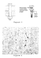
- the test method [Pettersen K and Fairchild S SAE Technical Paper 970226 ] involves applying an initial load (in this case 8 kN) through an assembly consisting of two identical bosses, 15mm thick and 16mm outside diameter, made of the test material and a high strength M8 bolt instrumented with strain gauges ( Figure 3 ). The change in load over 100h at an elevated temperature (150°C and 177°C) is measured continuously.
- the two significant loads are the initial load at ambient temperature, P I , and the load at the completion of the test after returning to ambient conditions, P F .
- the ratio of these two values (P F /P I ) is a measure of the bolt load retention behaviour of an alloy. There is often an initial increase in load as the bolted assembly is heated to the test temperature. This is the result of the combined thermal expansion of the bolted assembly and the yield deformation in the alloy bosses.
- THERMAL CONDUCTIVITY The thermal conductivity was measured on samples 30mm in diameter and 30mm long.
- CORROSION RESISTANCE The corrosion resistance of SC1 was compared to that of AZ91, using standard saline immersion tests at room temperature. The tests were carried out over a period of seven days in a saline environment (3.5% NaCl solution) with the pH stabilised to 11.0 using 1M NaOH solution. The corrosion products were removed from the test coupons using a chromic acid wash followed by an ethanol rinse.
- SC1 requires a T6 treatment (solution heat treatment in a controlled atmosphere, cold or warm water quench, and elevated temperature anneal) to fully develop its mechanical properties.
- the recommended heat treatment regime is a balance between mechanical property requirements and commercially acceptable holding times after casting.
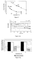
- the T6 microstructure of SC1 which is shown in Figure 4 , consists of grains of an ⁇ -Mg phase (A) locked by a magnesium-rare earth intermetallic phase (B) at grain boundaries and triple points. Clusters of rod-like precipitates (C) are present within the central regions of most grains.
- the intermetallic phase, B has a stoichiometry close to Mg 12 (La 0.43 Ce 0.57 ).
- Figure 5(a) shows both the tensile properties (the 0.2% proof strength and the ultimate tensile strength) and the compressive yield strength as a function of temperature.
- Figure 5(b) shows the tensile elongation, also as a function of temperature. It is significant to note that the mechanical properties of SC1 are extremely stable at elevated temperatures, with the proof strengths in both tension and compression being relatively unchanged between room temperature and 177°C. The room temperature properties of SC1 are nowhere near as high as most other magnesium sand casting alloys but it is the stability of these properties up to 177°C which makes this alloy particularly attractive for engine block applications.
- Typical bolt load retention curves for SC1, A319 and AE42 at 150°C and 8kN load are shown in Figure 7(a) .
- SC1 is in the T6 condition
- A319 is as sand cast
- AE42 is high pressure die cast (ie. all three alloys are in their normal operating condition).
- the increase in load occurring at the commencement of the test is the net result of the thermal expansion of the bolted assembly less the yield deformation in the alloy bosses.
- Two significant loads are the initial load at ambient temperature, P I (8kN in this case), and the load at the completion of the test after returning to ambient conditions, P F .
- FATIGUE PROPERTIES An engine block is continually subjected to cyclic stresses during service and it is necessary, therefore, to ensure that the material chosen for the block can withstand this fatigue loading.
- the fatigue strengths of SC1 at 10 6 and 10 7 cycles were determined at both 24 and 120°C, and the figures quoted in Table 5 are the stresses giving a 50% probability of fracture. The limits represent the stresses for the 10% and 90% probabilities of fracture. It should be noted that these results are for a maximum of 10 7 cycles, rather than the 5x10 7 specified in the design criteria. Nonetheless, the strengths are sufficiently high for the alloy to be considered to have met the target.
- CORROSION The corrosion behaviour of the alloy, both internally and externally, is of paramount importance. Corrosion on the internal surfaces may be controlled by the use of an appropriate engine coolant combined with careful design to ensure compatibility of all the metal components in contact with the coolant liquid.
- the corrosion resistance of the external surfaces will depend to a large extent on the composition of the alloy itself. There is no one test which can determine the corrosion resistance of an alloy in all environments and therefore SC1 has been compared to AZ91 using a standard saline immersion test. Both the alloys were in the T6 heat treated condition, and the mean weight loss rates over this time were found to be 0.864 mg/cm 2 /day for SC1 and 0.443 mg/cm 2 /day for AZ91E.
- the thermal conductivity of SC1 was found to be 102 W/mK, which is slightly less than that originally specified in the design criteria. However, with this information available, it is not difficult to modify the design of an engine block to accommodate this thermal conductivity value.
- SC1 is able to meet the following specifications:
- SC1 would make a commercially viable option as an engine block material.
Landscapes
- Chemical & Material Sciences (AREA)
- Organic Chemistry (AREA)
- Engineering & Computer Science (AREA)
- Materials Engineering (AREA)
- Mechanical Engineering (AREA)
- Metallurgy (AREA)
- Crystallography & Structural Chemistry (AREA)
- Physics & Mathematics (AREA)
- Thermal Sciences (AREA)
- Turbine Rotor Nozzle Sealing (AREA)
- Forging (AREA)
- Manufacture Of Metal Powder And Suspensions Thereof (AREA)
- Powder Metallurgy (AREA)
- Materials For Medical Uses (AREA)
- Dental Preparations (AREA)
- Investigating And Analyzing Materials By Characteristic Methods (AREA)
- Diaphragms For Electromechanical Transducers (AREA)
- Electroplating Methods And Accessories (AREA)
Abstract
Description
- The present invention relates to magnesium (Mg) alloys and, more particularly, to magnesium alloys which are resistant to creep at high temperatures.
- Magnesium alloys have been used for many years in applications where the material of construction is required to exhibit a high strength to weight ratio. Typically a component made from a magnesium alloy could be expected to have a weight about 70% of an aluminium (Al) alloy component of similar volume. The aerospace industry has accordingly been a significant user of magnesium alloys and magnesium alloys are used for many components in modern defence aircraft and spacecraft. However, one limitation preventing wider use of magnesium alloys is that, when compared to aluminium alloys, they typically have poorer resistance to creep at elevated temperatures.
- With the increasing needs to control international fuel consumption and reduce harmful emissions into the atmosphere, automobile manufacturers are being pressured into developing more fuel efficient vehicles. Reducing the overall weight of the vehicles is a key to achieving this goal. A major contributor to the weight of any vehicle is the engine itself, and the most significant component of the engine is the block, which makes up 20 - 25% of the total engine weight. In the past significant weight savings were made by introducing an aluminium alloy block to replace the traditional grey iron block, and further reductions of the order of 40% could be achieved if a magnesium alloy that could withstand the temperatures and stresses generated during engine operation was used. However, the development of such an alloy, which combines the desired elevated temperature mechanical properties with a cost effective production process, is necessary before a viable magnesium engine block manufacturing line could be considered. In recent years, the search for an elevated temperature magnesium alloy has focused primarily on the high pressure die casting (HPDC) processing route and several alloys have been developed. HPDC was considered to be the best option for achieving the high productivity rates required to counteract the probable high cost of the base magnesium alloy. However, HPDC is not necessarily the best process for the manufacture of an engine block and, in reality, the majority of blocks are still precision cast by gravity or low pressure sand casting.
- There are two major classes of magnesium sand casting alloys.
- (A) Alloys based on the magnesium-aluminium binary system, often with small additions of zinc (Zn) for improved strength and castability. These alloys have adequate room temperature mechanical properties, but do not perform well at elevated temperatures and are inappropriate at temperatures in excess of 150°C. These alloys do not contain expensive alloying elements and are widely used in areas where high temperature strength is not a requirement.
- (B) Alloys able to be grain refined by the addition of zirconium (Zr). The major alloying elements in this group are zinc, yttrium (Y), silver (Ag), thorium (Th), and the rare earth (RE) elements such as neodymium (Nd). Throughout this specification the expression "rare earth" is to be understood to mean any element or combination of elements with atomic numbers 57 to 71, ie. lanthanum (La) to lutetium (Lu). With the right choice of alloying additions, alloys in this group can have excellent room and elevated temperature mechanical properties. However, with the exception of zinc, the alloying additions within this group, including the grain refiner, are expensive with the result that the alloys are generally restricted to aeronautical applications.
- The magnesium alloy ML10, developed in the USSR, has been used for many years for cast parts intended for use in aircraft at temperatures up to 250°C. ML10 is a high strength magnesium alloy developed on the basis of the Mg-Nd-Zn-Zr system. ML19 alloy additionally contains yttrium.
- A paper by Mukhina et al entitled "Investigation of the Microstructure and Properties of Castable Neodymium and Yttrium-Bearing Magnesium Alloys at Elevated Temperatures" published in "Science and Heat Treatment" Vol 39, 1997, indicated typical compositions (% by weight) of ML10 and ML19 alloys are:
ML10 ML19 Nd 2.2-2.8 1.6-2.3 Y Nil 1.4-2.2 Zr 0.4-1.0 0.4-1.0 Zn 0.1-0.7 0.1-0.6 Mg Balance Balance Fe < 0.01 Si < 0.03 Cu < 0.03 Ni < 0.005 Al < 0.02 Be < 0.01 - The document
GB-A-1 378 281 - Alternatives which have been developed are alloys known to those in the art as QE22 (an Mg-Ag-Nd-Zr system alloy) and EH21 (an Mg-Nd-Zr-Th system alloy). However, these alternatives are expensive to manufacture as they contain significant quantities of silver and thorium respectively.
- Heat resistant grain refined magnesium alloys can be strengthened by a T6 heat treatment which comprises an elevated temperature solution treatment, followed by quenching, followed by an artificial aging at an elevated temperature. In heating before quenching the excess phases pass into solid solution. In the aging process refractory phases, in the form of finely dispersed submicroscopic particles, are segregated and these create microheterogeneities inside the grains of the solid solution, blocking diffusion and shear processes at elevated temperatures. This improves the mechanical properties, namely the ultimate long term strength and the creep resistance of the alloys at high temperature.
- To date, a sand casting magnesium alloy having desired elevated temperature (eg 150 - 200°C) properties at a reasonable cost has been unavailable. At least preferred embodiments of the present invention relate to such an alloy and the present invention is particularly, but not exclusively, directed to application with precision casting operations.
- The invention provides a magnesium based alloy defined in
claim 1. - Preferably, the alloy contains:
- (a) less than 0.1% titanium, more preferably less than 0.05% titanium, more preferably less than 0.01% titanium, and most preferably substantially no titanium;
- (b) less than 0.1% hafnium, more preferably less than 0.05% hafnium, more preferably less than 0.01% hafnium, and most preferably substantially no hafnium;
- (c) less than 0.05% aluminium, more preferably less than 0.02% aluminium, more preferably less than 0.01% aluminium, and most preferably substantially no aluminium;
- (d) less than 0.05% copper, more preferably less than 0.02% copper, more preferably less than 0.01% copper, and most preferably substantially no copper;
- (e) less than 0.05% nickel, more preferably less than 0.02% nickel, more preferably less than 0.01% nickel, and most preferably substantially no nickel;
- (f) less than 0.05% silicon, more preferably less than 0.02% silicon, more preferably less than 0.01% silicon, and most preferably substantially no silicon;
- (g) less than 0.05% silver, more preferably less than 0.02% silver, more preferably less than 0.01% silver, and most preferably substantially no silver;
- (h) less than 0.05% yttrium, more preferably less than 0.02% yttrium, more preferably less than 0.01% yttrium, and most preferably substantially no yttrium;
- (i) less than 0.05% thorium, more preferably less than 0.02% thorium, more preferably less than 0.01% thorium, and most preferably substantially no thorium;
- (j) less than 0.005% iron, most preferably substantially no iron; and
- (k) less than 0.001% strontium, most preferably substantially no strontium.
- Preferably, the alloy according to the present invention contains at least 95% magnesium, more preferably 95.5-97% magnesium, and most preferably about 96.3% magnesium.
- Preferably, the neodymium content is greater than 1.5%, more preferably greater than 1.6%, more preferably 1.6 - 1.8% and most preferably about 1.7%. The neodymium content may be derived from pure neodymium, neodymium contained within a mixture of rare earths such as a misch metal, or a combination thereof.
- Preferably, the content of rare earth(s) other than neodymium is 0.9-1.1%, more preferably about 1%. Preferably, the rare earth(s) other than neodymium are cerium (Ce), lanthanum (La), or a mixture thereof. Preferably, cerium comprises over half the weight of the rare earth elements other than neodymium, more preferably 60-80%, especially about 70% with lanthanum comprising substantially the balance. The rare earth(s) other than neodymium may be derived from pure rare earths, a mixture of rare earths such as a misch metal or a combination thereof. Preferably, the rare earths other than neodymium are derived from a cerium misch metal containing cerium, lanthanum, optionally neodymium, a modest amount of praseodymium (Pr) and trace amounts of other rare earths.
- The habit plane of the precipitating phase in Mg-Nd-Zn alloys is related to the zinc content, being prismatic at very low levels of Zn and basal at levels in excess of about 1wt%. The best strength results are obtained at zinc levels which promote a combination of the two habit planes. Preferably, the zinc content is less than 0.65%, more preferably 0.4-0.6%, more preferably 0.45-0.55%, most preferably about 0.5%.
- Reduction in iron content can be achieved by addition of zirconium which precipitates iron from molten alloy. Accordingly, the zirconium contents specified herein are residual zirconium contents. However, it is to be noted that zirconium may be incorporated at two different stages. Firstly, on manufacture of the alloy and secondly, following melting of the alloy just prior to casting.
- The elevated temperature properties of alloys of the present invention are reliant on adequate grain refinement and it is therefore necessary to maintain a level of zirconium in the melt beyond that required for iron removal. For desired tensile and compressive strength properties the grain size is preferably less than 200µm and more preferably less than 150µm. The relationship between creep resistance and grain size in alloys of the present invention is counter-intuitive. Conventional creep theory will predict that the creep resistance will decrease as the grain size decreases. However, alloys of the present invention have shown a minimum in creep resistance at a grain size of 200µm and improvements in creep resistance at smaller grain sizes. For optimum creep resistance the grain size is preferably less than 100µm and more preferably about 50µm. Preferably, the zirconium content will be the minimum amount required to achieve satisfactory iron removal and adequate grain refinement for the intended purpose. Typically, the zirconium content will be greater than 0.4%, preferably 0.4-0.6%, more preferably about 0.5%.
- Manganese is an optional component of the alloy which may be included if there is a need for additional iron removal over and above that achieved by zirconium, especially if the zirconium levels are relatively low, for example below 0.5wt%.
- Ideally, the incidental impurity content is zero but it is to be appreciated that this is essentially impossible. Accordingly, it is preferred that the incidental impurity content is less than 0.15%, more preferably less than 0.1%, more preferably less than 0.01%, and still more preferably less than 0.001%.
- The magnesium based alloy of the present invention preferably has a microstructure comprising equiaxed grains of magnesium based solid solution separated at the grain boundaries by a generally contiguous intergranular phase, the grains containing a uniform distribution of nano-scale precipitate platelets on more than one habit plane containing magnesium and neodymium, the intergranular phase consisting almost completely of rare earth elements, magnesium and a small amount of zinc, and the rare earth elements being substantially cerium and/or lanthanum.
- The grains may contain clusters of small spherical and globular precipitates. The spherical clusters may comprise fine rod-like precipitates. The globular precipitates may be predominantly zirconium plus zinc with a Zr:Zn atomic ratio of approximately 2:1. The rod-like precipitates may be predominantly zirconium plus zinc with a Zr:Zn atomic ratio of approximately 2:1.
- The expression "generally contiguous" as used in this specification is intended to mean that at least most of the intergranular phase is contiguous but that some gaps may exist between otherwise contiguous portions.
- The present invention provides a method defined in
claim 10 of producing a magnesium alloy article, the method comprising subjecting to a T6 heat treatment an article cast from an alloy defined above. - The method preferably comprises the steps of:
- (a) solidifying in a mould a casting of an alloy defined above,
- (b) heating the solidified casting at a temperature of 500-550°C for a first period of time,
- (c) quenching the casting, and
- (d) ageing the casting at a temperature of 200-230°C for a second period of time.
- Preferably, the first period of time is 6-24 hours and the second period of time is 3-24 hours.
- As an alternative, the method preferably comprises the step of:
- (i) melting an alloy defined above to form a molten alloy,
- (ii) introducing the molten alloy into a sand mould or permanent mould and allowing the molten alloy to solidify,
- (iii) removing the resultant solidified casting from the mould, and
- (iv) maintaining the casting within a first temperature range for a first period of time during which a portion of an intergranular phase of the casting is dissolved, and subsequently maintaining the casting within a second temperature range lower than the first temperature range for a second period of time during which nano-scale precipitate platelets are caused to precipitate within grains of the casting and at grain boundaries.
- The first temperature range is preferably 500-550°C, the second temperature range is preferably 200-230°C, the first period of time is preferably 6-24 hours, and the second period of time is preferably 3-24 hours.
- The present invention provides an engine block for an internal combustion engine formed from an alloy defined above, as specified in
claim 14. - Specific reference is made above to engine blocks but it is to be noted that alloys of the present invention may find use in other elevated temperature applications as well as low temperature applications.
- Samples were gravity cast from six alloy compositions (see Table 1) into a stepped plate mould having step thicknesses from 5mm to 25mm to form castings as illustrated in
Figure 1 . The rare earths other than neodymium were added as a Ce-based misch metal which contained cerium, lanthanum and some neodymium. The extra neodymium and the zinc were added in their elemental forms. The zirconium was added through a proprietary Mg-Zr master alloy. Standard melt handling procedures were used throughout preparation of the cast plates. Individual samples were then subjected to T6 heat treatment no. 3 of Table 2 which was determined to provide the best results. The solution heat treatment was carried out in a controlled atmosphere environment to prevent oxidation of the surface layers during the heat treatment. The resulting heat treated samples were then examined and tested to determine hardness, tensile strength, creep properties, corrosion resistance, fatigue performance and bolt load retention behaviour. Details are as shown in Tables 1 and 2 below.Table 1 - Compositions Evaluated Composition No. Wt%Zn Wt%Nd Wt%RE other than Nd Wt%Zr Wt% Total RE Comparative - A 0.42 1.40 1.33 0.47 2.73 Comparative - B 0.85 2.04 1.13 0.503 3.17 Comparative - C 0.88 1.68 0.82 0.519 2.50 Inventive - 1 0.41 1.63 0.8 0.495 2.43 Inventive - 2 0.67 1.64 0.81 0.459 2.45 Inventive - 3 0.55 1.70 0.94 0.55 2.64 Table 2 - T6 Heat Treatments Evaluated Heat Treatment No. Solution Treatment Quench Type Ageing 0 525° C 80°CWater 215°C 8hrs 16hours 1 525° C 80°C Water 215°C 8hrs 4hours 2 525° C 80°C Water 215°C 4hrs 150mins 3 525° C 80°C Water + 215°C 8hrs Aquaquench 4hours 4 525°C Air 215°C 8hrs 4hours 5 525° C 80°C Water + 215°C 8hrs Aquaquench 8hours 6 525° C 80°C Water + 215°C 8hrs Aquaquench 150mins 7 525° C 80°C Water + 215° 4hours 4hrs Aquaquench - The following conclusions were drawn from analysis of the results.
- Micrographs showed that Comparative Composition B had the greatest amount of intermetallic phase at the grain boundaries and triple points, which is consistent with it having the highest total rare earth content. Comparative Composition C and
Inventive Composition 1 had the least amounts of intermetallic phase, which is also consistent with them having a low total rare earth content. Micrographs ofInventive Composition 2 clearly showed a much larger and more variable grain size than any of the other compositions. This may be due to the slightly lower Zr content of this composition. All six compositions had the clouds of precipitates located approximately at the centre of the grains which are described elsewhere in this specification as being a Zr-Zn compound. - Hardness measurements were carried out and
Inventive Compositions - The tensile properties were determined at room temperature, 100°C, 150°C and 177°C. The composition variants were chosen so that the effects of several interactions could be investigated, and the following observations have been made.
-
Inventive Composition 1, which is similar to Inventive Composition 3 in Nd content but lower in Zn and other rare earth elements, has mechanical properties as good as or better than Inventive Composition 3, indicating that a low Zn and/or rare earth content is not necessarily detrimental to mechanical properties. - Comparative Composition A and
Inventive Composition 1 have very similar low Zn contents, whilst Comparative Composition A has a lower Nd content, a higher other rare earth content and a higher total rare earth content. At room temperatureInventive Composition 1 had the better proof stress and slightly higher elongation, which is consistent with there being extra Nd to provide strengthening and less Ce/La grain boundary intermetallic phase. At elevated temperature the room temperature trend was maintained. -
Inventive Compositions Inventive Compositions - Comparative Compositions B and C both had very similar (high) Zn contents with Comparative Composition B having a higher total rare earth content (from higher Nd and higher Ce/La) than Comparative Composition C. Comparative Composition B was consistently better than Comparative Composition C in terms of both proof stress and elongation at all temperatures; two properties which have a significant effect on creep behaviour.
- Creep tests were carried out on all compositions at a constant load of 90MPa and at temperatures of 150°C and 177°C. The steady state creep rates are listed in Table 3.
Table 3 Steady State Creep Rates (s-1) 90MPa 150°C 90MPa 177°C Comparative Composition A 7.05X10⁻¹¹ 3.6X10⁻¹⁰ Comparative Composition B 2.66x10⁻¹¹ 1.67x10⁻¹⁰ Comparative Composition C 4.07x10⁻¹¹ 2.5x10⁻¹⁰ Inventive Composition 15.56x10⁻¹¹ 5.31x10⁻¹⁰ Inventive Composition 22.59x10⁻¹¹ 3.6x10⁻¹⁰ Inventive Composition 3 2.80x10⁻¹¹ 1.40x10⁻¹⁰ - The stress to give a value of 0.1% creep strain after 100 hours is often quoted when comparing various creep resistant magnesium alloys. None of the six compositions had creep strains of this order after 100 hours at 150°C and 90MPa. Similarly, at 177°C, no composition exceeded this value after 100 hours, although creep strains in excess of that were reached at much longer test times. At 150°C all six compositions would be acceptable in terms of their creep behaviour.
- The zinc effect noticed in the tensile results was also evident in the creep results at 150°C, particularly with respect to the primary creep extension where
Inventive Composition 1 was better thanInventive Composition 2, which was in turn better than Comparative Composition C. The secondary creep rates were similar in these three compositions. Comparative Composition B, which had the highest Zn content but also a high rare earth content was also acceptable, indicating again that the deleterious effects of the high Zn content can be counteracted by high rare earth contents. - Comparative Composition A had a higher primary response than
Inventive Composition 1 and a slightly higher steady state creep rate, which indicates that although a Nd level of 1.4% is acceptable, 1.5% would be a preferable minimum and 1.6% even more preferable. - Samples of an alloy designated SC1 (96.3% Mg, 1.7% Nd, 1.0% RE (Ce:La of - 70:30), 0.5% Zn and 0.5% Zr) were prepared from gravity cast stepped plates, as shown in
Figure 1 . The Ce and La were added as a Ce-based misch metal which also contained some Nd. The extra Nd and the Zn were added in their elemental forms. The zirconium was added through a proprietary Mg-Zr master alloy. The mechanical properties presented here were determined from samples cut from the 15mm step, where the grain size achieved was approximately 40µm. Standard melt handling procedures and controlled environment heat treatment conditions were used throughout the preparation of the cast plates. - MICROSTRUCTURE - Samples for metallographic examination were polished with diamond pastes to 1µm followed by 0.05µm colloidal silica. Etching was carried out in a solution of nitric acid in ethylene glycol and water for approximately 12 seconds.
- TENSION AND COMPRESSION TESTS - The tensile properties were measured in accordance with ASTM E8 at 20, 100, 150 and 177°C in air using an Instron Testing Machine. Samples were held at temperature for 10 minutes prior to testing. The test specimens had a rectangular cross section (6mm x 3mm), with a gauge length of 25mm (
Figure 2(a) ). The compressive yield strength was determined in accordance with ASTM E9 at the same temperatures using cylindrical samples 15mm in diameter and 30mm long. The elastic modulus of the alloy was determined at room and elevated temperatures using a Piezoelectric Ultrasonic Composite Oscillator Technique (PUCOT) [Robinson, WH and Edgar A IEEE Transactions on Sonics and Ultrasonics, SU-21(2) 1974 98-105]. - CREEP TESTS - The creep behaviour was determined on constant load machines at temperatures of 150 and 177°C and stresses of 46, 60, 75 and 90 MPa, in temperature controlled silicone oil baths. The test samples were the same geometry as those used in the tensile testing, and the extension during creep was measured directly from the gauge lengths of the samples.
- FATIGUE TESTS - The fatigue strengths at 106 and 107 cycles were determined at 25 and 120°C in air. The specimens had a circular cross-section, 5mm in diameter and a 10mm gauge length (
Figure 2(b) ), polished to 1µm finish which corresponds approximately to the surface finish at the main bearing - the most highly stressed part of an engine block. Specimens were loaded axially in fully reversed tension-compression (ie. at zero mean stress) and the test frequency was 60 Hz, corresponding to nominal service conditions. There are several procedures for assessing the fatigue strength at a given life and here the staircase method was used (BS 3518 Part 5). - BOLT LOAD RETENTION (BLR) TESTS - Bolt load retention testing can be used to simulate the relaxation that may occur in service under a compressive loading. The test method [Pettersen K and Fairchild S SAE Technical Paper 970226] involves applying an initial load (in this
case 8 kN) through an assembly consisting of two identical bosses, 15mm thick and 16mm outside diameter, made of the test material and a high strength M8 bolt instrumented with strain gauges (Figure 3 ). The change in load over 100h at an elevated temperature (150°C and 177°C) is measured continuously. The two significant loads, in terms of defining the BLR behaviour, are the initial load at ambient temperature, PI, and the load at the completion of the test after returning to ambient conditions, PF. The ratio of these two values (PF/PI) is a measure of the bolt load retention behaviour of an alloy. There is often an initial increase in load as the bolted assembly is heated to the test temperature. This is the result of the combined thermal expansion of the bolted assembly and the yield deformation in the alloy bosses. - THERMAL CONDUCTIVITY - The thermal conductivity was measured on samples 30mm in diameter and 30mm long.
- CORROSION RESISTANCE - The corrosion resistance of SC1 was compared to that of AZ91, using standard saline immersion tests at room temperature. The tests were carried out over a period of seven days in a saline environment (3.5% NaCl solution) with the pH stabilised to 11.0 using 1M NaOH solution. The corrosion products were removed from the test coupons using a chromic acid wash followed by an ethanol rinse.
- MICROSTRUCTURE - Being a sand casting alloy, SC1 requires a T6 treatment (solution heat treatment in a controlled atmosphere, cold or warm water quench, and elevated temperature anneal) to fully develop its mechanical properties. The recommended heat treatment regime is a balance between mechanical property requirements and commercially acceptable holding times after casting. The T6 microstructure of SC1, which is shown in
Figure 4 , consists of grains of an α-Mg phase (A) locked by a magnesium-rare earth intermetallic phase (B) at grain boundaries and triple points. Clusters of rod-like precipitates (C) are present within the central regions of most grains. The intermetallic phase, B, has a stoichiometry close to Mg12 (La0.43Ce0.57). - TENSILE AND COMPRESSIVE STRENGTHS -
Figure 5(a) shows both the tensile properties (the 0.2% proof strength and the ultimate tensile strength) and the compressive yield strength as a function of temperature.Figure 5(b) shows the tensile elongation, also as a function of temperature. It is significant to note that the mechanical properties of SC1 are extremely stable at elevated temperatures, with the proof strengths in both tension and compression being relatively unchanged between room temperature and 177°C. The room temperature properties of SC1 are nowhere near as high as most other magnesium sand casting alloys but it is the stability of these properties up to 177°C which makes this alloy particularly attractive for engine block applications. - The results of the elastic modulus determination are shown in Table 4, and it is of note that the elastic modulus shows a drop of less than 10% at 177°C over the room temperature value.
Table 4 - Elastic Modulus of SC1 as determined using a PUCO technique. Young's Modulus (GPa) 25°C 100°C 177°C 45.8±0.3 43.9±0.3 41.9±0.3 - CREEP AND BOLT LOAD RETENTION BEHAVIOUR - The microstructure of SC1 is extremely stable at temperatures up to 177°C, and this is an important factor, together with the form and distribution of the grain boundary intermetallic phase, in achieving the requisite creep resistance. The use of a creep stress, being the stress to produce a creep strain of 0.1% after 100 hours at temperature, as a measure of creep resistance is an arbitrary one, but it is nonetheless a useful method for comparing alloy behaviour. Using this concept, the behaviour of SC1 may be compared to that of A319 (
Figure 6 ) and it is clear that the two alloys are very similar in their creep responses in thetemperature range 150 to 177°C. More importantly, however, it should be noted that the stresses required to produce a creep strain of 0.1% in SC1 after 100 hours at both 150 and 177°C are approaching the tensile yield strengths (0.2% offset) of the material. - Typical bolt load retention curves for SC1, A319 and AE42 at 150°C and 8kN load are shown in
Figure 7(a) . SC1 is in the T6 condition, A319 is as sand cast and AE42 is high pressure die cast (ie. all three alloys are in their normal operating condition). The increase in load occurring at the commencement of the test is the net result of the thermal expansion of the bolted assembly less the yield deformation in the alloy bosses. Two significant loads are the initial load at ambient temperature, PI (8kN in this case), and the load at the completion of the test after returning to ambient conditions, PF. The ratio of these two values is taken as a measure of the bolt load retention behaviour of an alloy, and has been used in this case to compare SC1 with die cast AE42 at 150 and 177°C (Figure 7(b) ). The bolt load retention behaviour at elevated temperatures again reflects the high temperature stability of this alloy and it is clear that SC1 is as good as the aluminium alloy A319 and superior to AE42 in this respect. - FATIGUE PROPERTIES - An engine block is continually subjected to cyclic stresses during service and it is necessary, therefore, to ensure that the material chosen for the block can withstand this fatigue loading. The fatigue strengths of SC1 at 106 and 107 cycles were determined at both 24 and 120°C, and the figures quoted in Table 5 are the stresses giving a 50% probability of fracture. The limits represent the stresses for the 10% and 90% probabilities of fracture. It should be noted that these results are for a maximum of 107 cycles, rather than the 5x10⁷ specified in the design criteria. Nonetheless, the strengths are sufficiently high for the alloy to be considered to have met the target.
Table 5 - Fatigue Strengths of SC1 at two temperatures (R=-1). Temperature Fatigue Strength (MPa) 106 cycles 107 cycles 24°C -80 75 ± 18 120°C 74 ± 9 71 ± 7 - denotes 12 samples only tested, rather than the 15 required by the standard - CORROSION - The corrosion behaviour of the alloy, both internally and externally, is of paramount importance. Corrosion on the internal surfaces may be controlled by the use of an appropriate engine coolant combined with careful design to ensure compatibility of all the metal components in contact with the coolant liquid. The corrosion resistance of the external surfaces will depend to a large extent on the composition of the alloy itself. There is no one test which can determine the corrosion resistance of an alloy in all environments and therefore SC1 has been compared to AZ91 using a standard saline immersion test. Both the alloys were in the T6 heat treated condition, and the mean weight loss rates over this time were found to be 0.864 mg/cm2/day for SC1 and 0.443 mg/cm2/day for AZ91E.
- THERMAL CONDUCTIVITY - The thermal conductivity of SC1 was found to be 102 W/mK, which is slightly less than that originally specified in the design criteria. However, with this information available, it is not difficult to modify the design of an engine block to accommodate this thermal conductivity value.
- SC1 is able to meet the following specifications:
- 0.2% proof strength of 120 MPa at room temperature and 110 MPa at 177°C.
- Creep resistance comparable to that of A319 at temperatures of 150°C and 177°C.
- Fatigue limit in excess of 50 MPa at room temperature.
- This combination of superior elevated temperature mechanical properties and calculated cost effectiveness suggests SC1 would make a commercially viable option as an engine block material.
Claims (15)
- A magnesium based alloy consisting of, by weight:1.4 - 1.9% neodymium,0.8 - 1.2% rare earth element(s) with atomic number(s) 57-71 other than neodymium,0.4 - 0.7% zinc,0.3 - 1% zirconium,0 - 0.3% manganese,0 - 0.1% oxidation inhibiting element(s),no more than 0.15% titanium,no more than 0.15% hafnium,no more than 0.1% aluminium,no more than 0.1% copper,no more than 0.1% nickel,no more than 0.1% silicon,no more than 0.1% silver,no more than 0.1% yttrium,no more than 0.1% thorium,no more than 0.01% iron,no more than 0.005% strontium,the balance being magnesium except for incidental impurities.
- A magnesium based alloy as claimed in claim 1 wherein the alloy consists of, by weight:1.4 - 1.9% neodymium,0.8 - 1.2% rare earth element(s) with atomic number(s) 57-71 other than neodymium,0.4 - 0.7% zinc,0.3 - 1% zirconium,0 - 0.3% manganese, and0 - 0.1% oxidation inhibiting element(s)the remainder being magnesium except for incidental impurities.
- An alloy as claimed in claim 1 or claim 2 wherein the magnesium content is 95.5 - 97% by weight.
- An alloy as claimed in any one of the preceding claims wherein the neodymium content is 1.6 - 1.8% by weight.
- An alloy as claimed in any one of the preceding claims wherein the content of rare earth(s) with atomic number(s) 57-71 other than neodymium is 0.9 - 1.1% by weight.
- An alloy as claimed in any one of the preceding claims which contains a plurality of rare earth elements with atomic numbers 57-71 other than neodymium and in which cerium comprises over half the weight of the rare earth elements other than neodymium.
- An alloy as claimed in any one of the preceding claims wherein the zirconium content is greater than 0.4% by weight.
- An alloy as claimed in any one of the preceding claims wherein the zinc content is 0.4 - 0.6% by weight.
- An alloy as claimed in any one of the preceding claims having a microstructure comprising equiaxed grains of magnesium based solid solution separated at the grain boundaries by a generally contiguous intergranular phase, the grains containing a uniform distribution of nano-scale precipitate platelets on more than one habit plane containing magnesium and neodymium, the intergranular phase having a stoichiometry close to Mg12(La0.43Ce0.57).
- A method of producing a magnesium alloy article, the method comprising subjecting to a T6 heat treatment an article cast from an alloy as claimed in any one of the preceding claims.
- A method of producing a magnesium alloy article as claimed in claim 10, wherein the T6 heat treatment comprises the steps of:(a) heating the cast article at a temperature of 500-550°C for a first period of time,(b) quenching the cast article, and(c) ageing the cast article at a temperature of 200- 230°C for a second period of time.
- A method of producing a magnesium alloy article as claimed in claim 10 comprising the steps of:(i) melting an alloy as claimed in any one of claims 1 - 9 to form a molten alloy,(ii) introducing the molten alloy into a sand mould or permanent mould and allowing the molten alloy to solidify, and(iii) removing the resultant solidified casting from the mould, and
the T6 heat treatment comprising:(iv) maintaining the casting within a first temperature range for a first period of time during which a portion of an intergranular phase of the casting is dissolved, and subsequently maintaining the casting within a second temperature range lower than the first temperature range for a second period of time during which nano-scale precipitate platelets are caused to precipitate within grains of the casting and at grain boundaries. - A method as claimed in claim 12 wherein the first temperature range is 500 - 550°C, the second temperature range is 200 - 230°C, the first period of time is 6-24 hours, and the second period of time is 3-24 hours.
- An engine block for an internal combustion engine formed from a magnesium alloy as claimed in any one of claims 1 - 9.
- An engine block for an internal combustion engine as claimed in claim 14 which is produced by a method as claimed in any one of claims 10 - 13.
Applications Claiming Priority (3)
| Application Number | Priority Date | Filing Date | Title |
|---|---|---|---|
| AUPS311202 | 2002-06-21 | ||
| AUPS3112A AUPS311202A0 (en) | 2002-06-21 | 2002-06-21 | Creep resistant magnesium alloy |
| PCT/AU2003/000774 WO2004001087A1 (en) | 2002-06-21 | 2003-06-20 | Creep resistant magnesium alloy |
Publications (3)
| Publication Number | Publication Date |
|---|---|
| EP1516074A1 EP1516074A1 (en) | 2005-03-23 |
| EP1516074A4 EP1516074A4 (en) | 2006-06-07 |
| EP1516074B1 true EP1516074B1 (en) | 2010-06-16 |
Family
ID=3836672
Family Applications (1)
| Application Number | Title | Priority Date | Filing Date |
|---|---|---|---|
| EP03760532A Expired - Lifetime EP1516074B1 (en) | 2002-06-21 | 2003-06-20 | Creep resistant magnesium alloy |
Country Status (15)
| Country | Link |
|---|---|
| US (1) | US7048812B2 (en) |
| EP (1) | EP1516074B1 (en) |
| JP (1) | JP2005530046A (en) |
| KR (1) | KR101127090B1 (en) |
| CN (1) | CN1318632C (en) |
| AT (1) | ATE471393T1 (en) |
| AU (2) | AUPS311202A0 (en) |
| CA (1) | CA2490419C (en) |
| DE (1) | DE60333011D1 (en) |
| MX (1) | MXPA05000083A (en) |
| NZ (1) | NZ537741A (en) |
| RU (1) | RU2320748C2 (en) |
| TW (1) | TW200402474A (en) |
| UA (1) | UA79971C2 (en) |
| WO (1) | WO2004001087A1 (en) |
Families Citing this family (66)
| Publication number | Priority date | Publication date | Assignee | Title |
|---|---|---|---|---|
| US9682425B2 (en) | 2009-12-08 | 2017-06-20 | Baker Hughes Incorporated | Coated metallic powder and method of making the same |
| DE102004043231A1 (en) | 2004-09-07 | 2006-03-09 | Biotronik Vi Patent Ag | Endoprosthesis made of magnesium alloy |
| US20060198869A1 (en) * | 2005-03-03 | 2006-09-07 | Icon Medical Corp. | Bioabsorable medical devices |
| US7682470B2 (en) | 2005-04-04 | 2010-03-23 | Cast Centre Pty Ltd | Magnesium alloy |
| BRPI0618517B1 (en) * | 2005-11-10 | 2018-01-09 | Magontec Gmbh | ALLOY AND MAGNESIUM FOUNDRY PROCESS |
| US7284528B2 (en) * | 2006-03-10 | 2007-10-23 | Ford Motor Company | Crank shaft support assembly |
| FR2904005B1 (en) * | 2006-07-20 | 2010-06-04 | Hispano Suiza Sa | PROCESS FOR MANUFACTURING HOT FORKED PIECES OF MAGNESIUM ALLOY. |
| IL177568A (en) * | 2006-08-17 | 2011-02-28 | Dead Sea Magnesium Ltd | Creep resistant magnesium alloy with improved ductility and fracture toughness for gravity casting applications |
| JP5525444B2 (en) * | 2007-08-31 | 2014-06-18 | カースト シーアールシー リミテッド | Magnesium-based alloy and method for producing the same |
| WO2009039581A1 (en) * | 2007-09-28 | 2009-04-02 | Cast Crc Limited | Permanent mould cast magnesium alloy |
| JP2011509350A (en) * | 2008-01-09 | 2011-03-24 | キャスト シーアールシー リミテッド | Magnesium alloy |
| RU2361945C1 (en) * | 2008-04-17 | 2009-07-20 | Юлия Алексеевна Щепочкина | Alloy on basis of magnesium |
| TW201000644A (en) * | 2008-06-24 | 2010-01-01 | Song-Ren Huang | Magnesium alloy composite material having doped grains |
| GB0817893D0 (en) * | 2008-09-30 | 2008-11-05 | Magnesium Elektron Ltd | Magnesium alloys containing rare earths |
| JP5540780B2 (en) * | 2009-05-29 | 2014-07-02 | 住友電気工業株式会社 | Magnesium alloy wire, bolt, nut and washer |
| US10240419B2 (en) | 2009-12-08 | 2019-03-26 | Baker Hughes, A Ge Company, Llc | Downhole flow inhibition tool and method of unplugging a seat |
| CN101787472B (en) * | 2010-03-18 | 2011-04-20 | 上海交通大学 | Heat-resistant forged magnesium-rare earth alloy and preparation method thereof |
| KR101646267B1 (en) * | 2010-05-28 | 2016-08-05 | 현대자동차주식회사 | HEAT RESISTING Mg ALLOY FOR GRAVITY CATING WITH HIGH CREEP RESISTANCE |
| JP5720926B2 (en) * | 2010-10-12 | 2015-05-20 | 住友電気工業株式会社 | Magnesium alloy wire, bolt, nut and washer |
| ES2423354T3 (en) * | 2011-02-01 | 2013-09-19 | Helmholtz-Zentrum Geesthacht Zentrum für Material- und Küstenforschung GmbH | Magnesium alloy containing rare earth metals |
| US9080098B2 (en) | 2011-04-28 | 2015-07-14 | Baker Hughes Incorporated | Functionally gradient composite article |
| US8631876B2 (en) | 2011-04-28 | 2014-01-21 | Baker Hughes Incorporated | Method of making and using a functionally gradient composite tool |
| US9139928B2 (en) | 2011-06-17 | 2015-09-22 | Baker Hughes Incorporated | Corrodible downhole article and method of removing the article from downhole environment |
| US9707739B2 (en) | 2011-07-22 | 2017-07-18 | Baker Hughes Incorporated | Intermetallic metallic composite, method of manufacture thereof and articles comprising the same |
| US9643250B2 (en) | 2011-07-29 | 2017-05-09 | Baker Hughes Incorporated | Method of controlling the corrosion rate of alloy particles, alloy particle with controlled corrosion rate, and articles comprising the particle |
| US9833838B2 (en) | 2011-07-29 | 2017-12-05 | Baker Hughes, A Ge Company, Llc | Method of controlling the corrosion rate of alloy particles, alloy particle with controlled corrosion rate, and articles comprising the particle |
| US9033055B2 (en) | 2011-08-17 | 2015-05-19 | Baker Hughes Incorporated | Selectively degradable passage restriction and method |
| US9090956B2 (en) | 2011-08-30 | 2015-07-28 | Baker Hughes Incorporated | Aluminum alloy powder metal compact |
| US9109269B2 (en) | 2011-08-30 | 2015-08-18 | Baker Hughes Incorporated | Magnesium alloy powder metal compact |
| US9856547B2 (en) | 2011-08-30 | 2018-01-02 | Bakers Hughes, A Ge Company, Llc | Nanostructured powder metal compact |
| US9643144B2 (en) | 2011-09-02 | 2017-05-09 | Baker Hughes Incorporated | Method to generate and disperse nanostructures in a composite material |
| US9010416B2 (en) | 2012-01-25 | 2015-04-21 | Baker Hughes Incorporated | Tubular anchoring system and a seat for use in the same |
| US9605508B2 (en) | 2012-05-08 | 2017-03-28 | Baker Hughes Incorporated | Disintegrable and conformable metallic seal, and method of making the same |
| US9816339B2 (en) | 2013-09-03 | 2017-11-14 | Baker Hughes, A Ge Company, Llc | Plug reception assembly and method of reducing restriction in a borehole |
| CN103695744B (en) * | 2014-01-16 | 2015-09-23 | 张霞 | A kind of nanoparticle reinforced magnesium alloy and its preparation method |
| CN104862566A (en) * | 2014-02-21 | 2015-08-26 | 中国科学院金属研究所 | High-strength high-plasticity medical magnesium alloy, and preparation method and applications thereof |
| US11167343B2 (en) | 2014-02-21 | 2021-11-09 | Terves, Llc | Galvanically-active in situ formed particles for controlled rate dissolving tools |
| US10689740B2 (en) | 2014-04-18 | 2020-06-23 | Terves, LLCq | Galvanically-active in situ formed particles for controlled rate dissolving tools |
| US10150713B2 (en) | 2014-02-21 | 2018-12-11 | Terves, Inc. | Fluid activated disintegrating metal system |
| CN104060139A (en) * | 2014-07-01 | 2014-09-24 | 张家港市佳晟机械有限公司 | High-functional magnesium alloy |
| GB201413327D0 (en) | 2014-07-28 | 2014-09-10 | Magnesium Elektron Ltd | Corrodible downhole article |
| CN104532029A (en) * | 2014-12-15 | 2015-04-22 | 镁联科技(芜湖)有限公司 | High-tenacity magnesium alloy as well as preparation and application of high-tenacity magnesium alloy |
| CN104561712A (en) * | 2014-12-15 | 2015-04-29 | 镁联科技(芜湖)有限公司 | Creep-resistant magnesium alloy as well as preparation method and application thereof |
| US9910026B2 (en) | 2015-01-21 | 2018-03-06 | Baker Hughes, A Ge Company, Llc | High temperature tracers for downhole detection of produced water |
| US10378303B2 (en) | 2015-03-05 | 2019-08-13 | Baker Hughes, A Ge Company, Llc | Downhole tool and method of forming the same |
| JP6594663B2 (en) * | 2015-05-27 | 2019-10-23 | 本田技研工業株式会社 | Heat-resistant magnesium casting alloy and its manufacturing method |
| US10221637B2 (en) | 2015-08-11 | 2019-03-05 | Baker Hughes, A Ge Company, Llc | Methods of manufacturing dissolvable tools via liquid-solid state molding |
| US10016810B2 (en) | 2015-12-14 | 2018-07-10 | Baker Hughes, A Ge Company, Llc | Methods of manufacturing degradable tools using a galvanic carrier and tools manufactured thereof |
| RU2615934C1 (en) * | 2016-06-16 | 2017-04-11 | Юлия Алексеевна Щепочкина | Alloy on base of magnesium |
| GB201700714D0 (en) * | 2017-01-16 | 2017-03-01 | Magnesium Elektron Ltd | Corrodible downhole article |
| CN107201470B (en) * | 2017-05-10 | 2019-07-23 | 上海大学 | A kind of magnesium alloy and preparation method thereof having both high heat dispersion, excellent mechanical performances |
| CN106967915B (en) * | 2017-06-02 | 2019-03-12 | 哈尔滨工业大学 | A kind of ultra-high strength and high modulus easily soluble Mg-Y-Ni-Zr-Ca magnesium alloy and preparation method thereof |
| CA3012511A1 (en) | 2017-07-27 | 2019-01-27 | Terves Inc. | Degradable metal matrix composite |
| CN107723548A (en) * | 2017-11-16 | 2018-02-23 | 上海电力学院 | A kind of high intensity Mg Y Ni Zr alloys and preparation method thereof |
| CN108004423A (en) * | 2017-11-30 | 2018-05-08 | 于海松 | The synthesis technique of high-performance magnesium base alloy |
| CN108715964B (en) * | 2018-06-07 | 2019-10-15 | 河南科技大学 | A kind of rare earth magnesium alloy and preparation method thereof |
| CN109295369A (en) * | 2018-11-23 | 2019-02-01 | 上海交通大学 | A kind of rare earth magnesium alloy containing cerium and its heat treatment method |
| RU2757572C1 (en) * | 2020-12-08 | 2021-10-18 | Публичное акционерное общество "Авиационная корпорация "Рубин" | Magnesium alloy for sealed castings |
| CN112647002A (en) * | 2020-12-25 | 2021-04-13 | 山西瑞格金属新材料有限公司 | High-toughness high-heat-conductivity magnesium alloy for ultrathin wall component and preparation method thereof |
| CN113106277B (en) * | 2021-04-10 | 2022-03-01 | 中北大学 | Preparation method of magnesium-zinc-yttrium quasicrystal and titanium carbide synergistically reinforced magnesium matrix composite |
| CN114459849B (en) * | 2021-12-22 | 2023-08-25 | 西南交通大学 | Preparation method and test method of high-strength rare earth magnesium alloy |
| CN114351020B (en) * | 2021-12-30 | 2022-12-13 | 台山市中镁科技有限公司 | Magnesium alloy casting and preparation method and application thereof |
| CN114635068B (en) * | 2022-03-11 | 2023-06-23 | 上海交通大学 | High-strength and high-toughness cast magnesium rare earth alloy and preparation method thereof |
| CN114855041A (en) * | 2022-05-06 | 2022-08-05 | 上海大学 | Die-casting magnesium alloy containing rare earth and forming process thereof |
| CN114850727B (en) * | 2022-05-19 | 2023-01-20 | 吉林大学 | High-performance antioxidant rare earth magnesium alloy ultra-long thin wire and preparation method thereof |
| CN116356171B (en) * | 2023-05-31 | 2023-09-12 | 北京爱康宜诚医疗器材有限公司 | Medical magnesium alloy and preparation method thereof |
Family Cites Families (10)
| Publication number | Priority date | Publication date | Assignee | Title |
|---|---|---|---|---|
| GB801865A (en) * | 1955-11-18 | 1958-09-24 | Dow Chemical Co | Magnesium alloy |
| GB1237035A (en) * | 1969-08-20 | 1971-06-30 | Tsi Travmatologii I Ortopedii | Magnesium-base alloy for use in bone surgery |
| GB1378281A (en) * | 1973-03-14 | 1974-12-27 | Tikhova N M Blokhina V A Antip | Magnesium-based alloy |
| FR2223471A1 (en) * | 1973-04-02 | 1974-10-25 | Tikhova Nina | Heat-resistant, structural magnesium-base alloy - contg yttrium, neody-mium, zinc, zirconium and in addition copper and manganese |
| SU585940A1 (en) * | 1974-02-05 | 1977-12-30 | Пермский Моторостроительный Завод Им.Я.М.Свердлова | Welding wire composition |
| GB1463608A (en) * | 1974-12-30 | 1977-02-02 | Magnesium Elektron Ltd | Magnesium alloys |
| GB1527877A (en) * | 1975-12-17 | 1978-10-11 | Magnesium Elektron Ltd | Magnesium alloys |
| SU1360223A1 (en) | 1985-09-24 | 1994-10-15 | В.А. Блохина | Magnesium-based alloys |
| SU1394726A1 (en) * | 1986-04-07 | 1994-10-30 | Антипова А.П. | Magnesium base alloy |
| GB9502238D0 (en) * | 1995-02-06 | 1995-03-29 | Alcan Int Ltd | Magnesium alloys |
-
2002
- 2002-06-21 AU AUPS3112A patent/AUPS311202A0/en not_active Abandoned
-
2003
- 2003-06-20 RU RU2005101317/02A patent/RU2320748C2/en not_active IP Right Cessation
- 2003-06-20 MX MXPA05000083A patent/MXPA05000083A/en active IP Right Grant
- 2003-06-20 CA CA2490419A patent/CA2490419C/en not_active Expired - Fee Related
- 2003-06-20 JP JP2004514430A patent/JP2005530046A/en active Pending
- 2003-06-20 KR KR1020117001790A patent/KR101127090B1/en not_active Expired - Fee Related
- 2003-06-20 NZ NZ537741A patent/NZ537741A/en not_active IP Right Cessation
- 2003-06-20 AT AT03760532T patent/ATE471393T1/en active
- 2003-06-20 US US10/469,113 patent/US7048812B2/en not_active Expired - Fee Related
- 2003-06-20 EP EP03760532A patent/EP1516074B1/en not_active Expired - Lifetime
- 2003-06-20 AU AU2003232527A patent/AU2003232527B2/en not_active Ceased
- 2003-06-20 CN CNB038189399A patent/CN1318632C/en not_active Expired - Fee Related
- 2003-06-20 DE DE60333011T patent/DE60333011D1/en not_active Expired - Lifetime
- 2003-06-20 TW TW092116800A patent/TW200402474A/en unknown
- 2003-06-20 WO PCT/AU2003/000774 patent/WO2004001087A1/en not_active Ceased
- 2003-06-20 UA UAA200500507A patent/UA79971C2/en unknown
Also Published As
| Publication number | Publication date |
|---|---|
| AU2003232527A1 (en) | 2004-01-06 |
| KR20110013579A (en) | 2011-02-09 |
| CN1675395A (en) | 2005-09-28 |
| US20050002821A1 (en) | 2005-01-06 |
| JP2005530046A (en) | 2005-10-06 |
| CA2490419C (en) | 2012-03-20 |
| TW200402474A (en) | 2004-02-16 |
| AU2003232527B2 (en) | 2009-02-05 |
| UA79971C2 (en) | 2007-08-10 |
| ATE471393T1 (en) | 2010-07-15 |
| RU2320748C2 (en) | 2008-03-27 |
| MXPA05000083A (en) | 2005-04-08 |
| WO2004001087A1 (en) | 2003-12-31 |
| CA2490419A1 (en) | 2003-12-31 |
| NZ537741A (en) | 2005-07-29 |
| EP1516074A4 (en) | 2006-06-07 |
| KR101127090B1 (en) | 2012-03-22 |
| DE60333011D1 (en) | 2010-07-29 |
| AUPS311202A0 (en) | 2002-07-18 |
| RU2005101317A (en) | 2005-10-10 |
| EP1516074A1 (en) | 2005-03-23 |
| US7048812B2 (en) | 2006-05-23 |
| CN1318632C (en) | 2007-05-30 |
Similar Documents
| Publication | Publication Date | Title |
|---|---|---|
| AU2003232527B2 (en) | Creep resistant magnesium alloy | |
| Isadare et al. | Effect of heat treatment on some mechanical properties of 7075 aluminium alloy | |
| EP3084027B1 (en) | HIGH PERFORMANCE AlSiMgCu CASTING ALLOY | |
| EP2112244A1 (en) | High strength L12 aluminium alloys | |
| BR102018007241B1 (en) | ALUMINUM ALLOY, AND, METHOD FOR PRODUCING AN ALUMINUM ALLOY | |
| WO2009039581A1 (en) | Permanent mould cast magnesium alloy | |
| Hao et al. | Microstructure and mechanical properties of extruded Mg–8.5 Gd–2.3 Y–1.8 Ag–0.4 Zr alloy | |
| JP4185247B2 (en) | Aluminum-based alloy and heat treatment method thereof | |
| CN112813323B (en) | A kind of pre-deformed magnesium alloy and its processing method | |
| EP2582855B1 (en) | Castable heat resistant aluminium alloy | |
| Mohammadi et al. | Influence of Heat Treatment on the AA6061 and AA6063 Aluminum Alloys Behavior at Elevated Deformation Temperature. | |
| Odusote et al. | Mechanical properties and microstructure of precipitation-hardened Al-Cu-Zn alloys | |
| CN112831737B (en) | A kind of magnesium alloy processing method for improving high temperature creep performance | |
| JP7565728B2 (en) | Aluminum alloy forged member and manufacturing method thereof | |
| WO2017123186A1 (en) | Tial-based alloys having improved creep strength by strengthening of gamma phase | |
| Bettles et al. | AMC-SC1: A new magnesium alloy suitable for powertrain applications | |
| EA034631B1 (en) | Heat resistant ultrafine-grain aluminium conductor alloy and method of production thereof | |
| Rathod et al. | Influence of precipitation hardening in aluminum based systems: A literature review | |
| JP2006161103A (en) | Aluminum alloy member and manufacturing method thereof | |
| CN118773459A (en) | Aluminum alloy bar for forging and preparation method thereof | |
| CN101087895B (en) | Aluminum-based alloy and molded body made of the alloy | |
| Bolibruchová et al. | Effect of Ti on selected properties of AlSi7Mg0. 3Cu0. 5 alloy with constant addition of Zr | |
| Bettles et al. | AMC-SC1: An elevated temperature magnesium alloy suitable for precision sand casting of powertrain components | |
| KR20050016609A (en) | Creep resistant magnesium alloy | |
| JP2010280927A (en) | TiAl alloy internal combustion engine parts |
Legal Events
| Date | Code | Title | Description |
|---|---|---|---|
| PUAI | Public reference made under article 153(3) epc to a published international application that has entered the european phase |
Free format text: ORIGINAL CODE: 0009012 |
|
| 17P | Request for examination filed |
Effective date: 20041222 |
|
| AK | Designated contracting states |
Kind code of ref document: A1 Designated state(s): AT BE BG CH CY CZ DE DK EE ES FI FR GB GR HU IE IT LI LU MC NL PT RO SE SI SK TR |
|
| AX | Request for extension of the european patent |
Extension state: AL LT LV MK |
|
| DAX | Request for extension of the european patent (deleted) | ||
| A4 | Supplementary search report drawn up and despatched |
Effective date: 20060510 |
|
| 17Q | First examination report despatched |
Effective date: 20081124 |
|
| GRAP | Despatch of communication of intention to grant a patent |
Free format text: ORIGINAL CODE: EPIDOSNIGR1 |
|
| GRAS | Grant fee paid |
Free format text: ORIGINAL CODE: EPIDOSNIGR3 |
|
| GRAA | (expected) grant |
Free format text: ORIGINAL CODE: 0009210 |
|
| AK | Designated contracting states |
Kind code of ref document: B1 Designated state(s): AT BE BG CH CY CZ DE DK EE ES FI FR GB GR HU IE IT LI LU MC NL PT RO SE SI SK TR |
|
| REG | Reference to a national code |
Ref country code: CH Ref legal event code: EP |
|
| REG | Reference to a national code |
Ref country code: IE Ref legal event code: FG4D |
|
| REF | Corresponds to: |
Ref document number: 60333011 Country of ref document: DE Date of ref document: 20100729 Kind code of ref document: P |
|
| REG | Reference to a national code |
Ref country code: NL Ref legal event code: VDEP Effective date: 20100616 |
|
| PG25 | Lapsed in a contracting state [announced via postgrant information from national office to epo] |
Ref country code: SE Free format text: LAPSE BECAUSE OF FAILURE TO SUBMIT A TRANSLATION OF THE DESCRIPTION OR TO PAY THE FEE WITHIN THE PRESCRIBED TIME-LIMIT Effective date: 20100616 |
|
| PG25 | Lapsed in a contracting state [announced via postgrant information from national office to epo] |
Ref country code: FI Free format text: LAPSE BECAUSE OF FAILURE TO SUBMIT A TRANSLATION OF THE DESCRIPTION OR TO PAY THE FEE WITHIN THE PRESCRIBED TIME-LIMIT Effective date: 20100616 Ref country code: SI Free format text: LAPSE BECAUSE OF FAILURE TO SUBMIT A TRANSLATION OF THE DESCRIPTION OR TO PAY THE FEE WITHIN THE PRESCRIBED TIME-LIMIT Effective date: 20100616 |
|
| PG25 | Lapsed in a contracting state [announced via postgrant information from national office to epo] |
Ref country code: CY Free format text: LAPSE BECAUSE OF FAILURE TO SUBMIT A TRANSLATION OF THE DESCRIPTION OR TO PAY THE FEE WITHIN THE PRESCRIBED TIME-LIMIT Effective date: 20100616 Ref country code: GR Free format text: LAPSE BECAUSE OF FAILURE TO SUBMIT A TRANSLATION OF THE DESCRIPTION OR TO PAY THE FEE WITHIN THE PRESCRIBED TIME-LIMIT Effective date: 20100917 |
|
| PG25 | Lapsed in a contracting state [announced via postgrant information from national office to epo] |
Ref country code: NL Free format text: LAPSE BECAUSE OF FAILURE TO SUBMIT A TRANSLATION OF THE DESCRIPTION OR TO PAY THE FEE WITHIN THE PRESCRIBED TIME-LIMIT Effective date: 20100616 Ref country code: MC Free format text: LAPSE BECAUSE OF NON-PAYMENT OF DUE FEES Effective date: 20100630 Ref country code: EE Free format text: LAPSE BECAUSE OF FAILURE TO SUBMIT A TRANSLATION OF THE DESCRIPTION OR TO PAY THE FEE WITHIN THE PRESCRIBED TIME-LIMIT Effective date: 20100616 |
|
| REG | Reference to a national code |
Ref country code: CH Ref legal event code: PL |
|
| PG25 | Lapsed in a contracting state [announced via postgrant information from national office to epo] |
Ref country code: SK Free format text: LAPSE BECAUSE OF FAILURE TO SUBMIT A TRANSLATION OF THE DESCRIPTION OR TO PAY THE FEE WITHIN THE PRESCRIBED TIME-LIMIT Effective date: 20100616 Ref country code: BE Free format text: LAPSE BECAUSE OF FAILURE TO SUBMIT A TRANSLATION OF THE DESCRIPTION OR TO PAY THE FEE WITHIN THE PRESCRIBED TIME-LIMIT Effective date: 20100616 Ref country code: CZ Free format text: LAPSE BECAUSE OF FAILURE TO SUBMIT A TRANSLATION OF THE DESCRIPTION OR TO PAY THE FEE WITHIN THE PRESCRIBED TIME-LIMIT Effective date: 20100616 Ref country code: PT Free format text: LAPSE BECAUSE OF FAILURE TO SUBMIT A TRANSLATION OF THE DESCRIPTION OR TO PAY THE FEE WITHIN THE PRESCRIBED TIME-LIMIT Effective date: 20101018 Ref country code: RO Free format text: LAPSE BECAUSE OF FAILURE TO SUBMIT A TRANSLATION OF THE DESCRIPTION OR TO PAY THE FEE WITHIN THE PRESCRIBED TIME-LIMIT Effective date: 20100616 |
|
| PG25 | Lapsed in a contracting state [announced via postgrant information from national office to epo] |
Ref country code: IT Free format text: LAPSE BECAUSE OF FAILURE TO SUBMIT A TRANSLATION OF THE DESCRIPTION OR TO PAY THE FEE WITHIN THE PRESCRIBED TIME-LIMIT Effective date: 20100616 |
|
| PLBE | No opposition filed within time limit |
Free format text: ORIGINAL CODE: 0009261 |
|
| STAA | Information on the status of an ep patent application or granted ep patent |
Free format text: STATUS: NO OPPOSITION FILED WITHIN TIME LIMIT |
|
| PG25 | Lapsed in a contracting state [announced via postgrant information from national office to epo] |
Ref country code: DK Free format text: LAPSE BECAUSE OF FAILURE TO SUBMIT A TRANSLATION OF THE DESCRIPTION OR TO PAY THE FEE WITHIN THE PRESCRIBED TIME-LIMIT Effective date: 20100616 Ref country code: IE Free format text: LAPSE BECAUSE OF NON-PAYMENT OF DUE FEES Effective date: 20100620 Ref country code: CH Free format text: LAPSE BECAUSE OF NON-PAYMENT OF DUE FEES Effective date: 20100630 Ref country code: LI Free format text: LAPSE BECAUSE OF NON-PAYMENT OF DUE FEES Effective date: 20100630 |
|
| 26N | No opposition filed |
Effective date: 20110317 |
|
| REG | Reference to a national code |
Ref country code: FR Ref legal event code: ST Effective date: 20110228 |
|
| REG | Reference to a national code |
Ref country code: DE Ref legal event code: R097 Ref document number: 60333011 Country of ref document: DE Effective date: 20110316 |
|
| PG25 | Lapsed in a contracting state [announced via postgrant information from national office to epo] |
Ref country code: FR Free format text: LAPSE BECAUSE OF NON-PAYMENT OF DUE FEES Effective date: 20100816 |
|
| PGFP | Annual fee paid to national office [announced via postgrant information from national office to epo] |
Ref country code: DE Payment date: 20120613 Year of fee payment: 10 |
|
| PGFP | Annual fee paid to national office [announced via postgrant information from national office to epo] |
Ref country code: GB Payment date: 20120620 Year of fee payment: 10 |
|
| PG25 | Lapsed in a contracting state [announced via postgrant information from national office to epo] |
Ref country code: HU Free format text: LAPSE BECAUSE OF FAILURE TO SUBMIT A TRANSLATION OF THE DESCRIPTION OR TO PAY THE FEE WITHIN THE PRESCRIBED TIME-LIMIT Effective date: 20101217 Ref country code: BG Free format text: LAPSE BECAUSE OF FAILURE TO SUBMIT A TRANSLATION OF THE DESCRIPTION OR TO PAY THE FEE WITHIN THE PRESCRIBED TIME-LIMIT Effective date: 20100616 Ref country code: LU Free format text: LAPSE BECAUSE OF NON-PAYMENT OF DUE FEES Effective date: 20100620 |
|
| PG25 | Lapsed in a contracting state [announced via postgrant information from national office to epo] |
Ref country code: TR Free format text: LAPSE BECAUSE OF FAILURE TO SUBMIT A TRANSLATION OF THE DESCRIPTION OR TO PAY THE FEE WITHIN THE PRESCRIBED TIME-LIMIT Effective date: 20100616 |
|
| PGFP | Annual fee paid to national office [announced via postgrant information from national office to epo] |
Ref country code: AT Payment date: 20120529 Year of fee payment: 10 |
|
| PG25 | Lapsed in a contracting state [announced via postgrant information from national office to epo] |
Ref country code: BG Free format text: LAPSE BECAUSE OF FAILURE TO SUBMIT A TRANSLATION OF THE DESCRIPTION OR TO PAY THE FEE WITHIN THE PRESCRIBED TIME-LIMIT Effective date: 20100916 |
|
| PG25 | Lapsed in a contracting state [announced via postgrant information from national office to epo] |
Ref country code: ES Free format text: LAPSE BECAUSE OF FAILURE TO SUBMIT A TRANSLATION OF THE DESCRIPTION OR TO PAY THE FEE WITHIN THE PRESCRIBED TIME-LIMIT Effective date: 20100927 |
|
| REG | Reference to a national code |
Ref country code: AT Ref legal event code: MM01 Ref document number: 471393 Country of ref document: AT Kind code of ref document: T Effective date: 20130620 |
|
| GBPC | Gb: european patent ceased through non-payment of renewal fee |
Effective date: 20130620 |
|
| REG | Reference to a national code |
Ref country code: DE Ref legal event code: R119 Ref document number: 60333011 Country of ref document: DE Effective date: 20140101 |
|
| PG25 | Lapsed in a contracting state [announced via postgrant information from national office to epo] |
Ref country code: GB Free format text: LAPSE BECAUSE OF NON-PAYMENT OF DUE FEES Effective date: 20130620 Ref country code: DE Free format text: LAPSE BECAUSE OF NON-PAYMENT OF DUE FEES Effective date: 20140101 |
|
| PG25 | Lapsed in a contracting state [announced via postgrant information from national office to epo] |
Ref country code: AT Free format text: LAPSE BECAUSE OF NON-PAYMENT OF DUE FEES Effective date: 20130620 |