EP1515547A2 - Optoelektronische Überwachungseinrichtung für Kraftfahrzeuge - Google Patents
Optoelektronische Überwachungseinrichtung für Kraftfahrzeuge Download PDFInfo
- Publication number
- EP1515547A2 EP1515547A2 EP04021290A EP04021290A EP1515547A2 EP 1515547 A2 EP1515547 A2 EP 1515547A2 EP 04021290 A EP04021290 A EP 04021290A EP 04021290 A EP04021290 A EP 04021290A EP 1515547 A2 EP1515547 A2 EP 1515547A2
- Authority
- EP
- European Patent Office
- Prior art keywords
- integration time
- monitoring device
- function
- optoelectronic monitoring
- light intensity
- Prior art date
- Legal status (The legal status is an assumption and is not a legal conclusion. Google has not performed a legal analysis and makes no representation as to the accuracy of the status listed.)
- Granted
Links
Images


Classifications
-
- B—PERFORMING OPERATIONS; TRANSPORTING
- B60—VEHICLES IN GENERAL
- B60Q—ARRANGEMENT OF SIGNALLING OR LIGHTING DEVICES, THE MOUNTING OR SUPPORTING THEREOF OR CIRCUITS THEREFOR, FOR VEHICLES IN GENERAL
- B60Q9/00—Arrangement or adaptation of signal devices not provided for in one of main groups B60Q1/00 - B60Q7/00, e.g. haptic signalling
- B60Q9/002—Arrangement or adaptation of signal devices not provided for in one of main groups B60Q1/00 - B60Q7/00, e.g. haptic signalling for parking purposes, e.g. for warning the driver that his vehicle has contacted or is about to contact an obstacle
- B60Q9/004—Arrangement or adaptation of signal devices not provided for in one of main groups B60Q1/00 - B60Q7/00, e.g. haptic signalling for parking purposes, e.g. for warning the driver that his vehicle has contacted or is about to contact an obstacle using wave sensors
- B60Q9/005—Arrangement or adaptation of signal devices not provided for in one of main groups B60Q1/00 - B60Q7/00, e.g. haptic signalling for parking purposes, e.g. for warning the driver that his vehicle has contacted or is about to contact an obstacle using wave sensors using a video camera
-
- B—PERFORMING OPERATIONS; TRANSPORTING
- B60—VEHICLES IN GENERAL
- B60Q—ARRANGEMENT OF SIGNALLING OR LIGHTING DEVICES, THE MOUNTING OR SUPPORTING THEREOF OR CIRCUITS THEREFOR, FOR VEHICLES IN GENERAL
- B60Q9/00—Arrangement or adaptation of signal devices not provided for in one of main groups B60Q1/00 - B60Q7/00, e.g. haptic signalling
- B60Q9/002—Arrangement or adaptation of signal devices not provided for in one of main groups B60Q1/00 - B60Q7/00, e.g. haptic signalling for parking purposes, e.g. for warning the driver that his vehicle has contacted or is about to contact an obstacle
- B60Q9/004—Arrangement or adaptation of signal devices not provided for in one of main groups B60Q1/00 - B60Q7/00, e.g. haptic signalling for parking purposes, e.g. for warning the driver that his vehicle has contacted or is about to contact an obstacle using wave sensors
- B60Q9/006—Arrangement or adaptation of signal devices not provided for in one of main groups B60Q1/00 - B60Q7/00, e.g. haptic signalling for parking purposes, e.g. for warning the driver that his vehicle has contacted or is about to contact an obstacle using wave sensors using a distance sensor
-
- B—PERFORMING OPERATIONS; TRANSPORTING
- B60—VEHICLES IN GENERAL
- B60T—VEHICLE BRAKE CONTROL SYSTEMS OR PARTS THEREOF; BRAKE CONTROL SYSTEMS OR PARTS THEREOF, IN GENERAL; ARRANGEMENT OF BRAKING ELEMENTS ON VEHICLES IN GENERAL; PORTABLE DEVICES FOR PREVENTING UNWANTED MOVEMENT OF VEHICLES; VEHICLE MODIFICATIONS TO FACILITATE COOLING OF BRAKES
- B60T7/00—Brake-action initiating means
- B60T7/12—Brake-action initiating means for automatic initiation; for initiation not subject to will of driver or passenger
- B60T7/22—Brake-action initiating means for automatic initiation; for initiation not subject to will of driver or passenger initiated by contact of vehicle, e.g. bumper, with an external object, e.g. another vehicle, or by means of contactless obstacle detectors mounted on the vehicle
-
- H—ELECTRICITY
- H04—ELECTRIC COMMUNICATION TECHNIQUE
- H04N—PICTORIAL COMMUNICATION, e.g. TELEVISION
- H04N23/00—Cameras or camera modules comprising electronic image sensors; Control thereof
- H04N23/70—Circuitry for compensating brightness variation in the scene
- H04N23/73—Circuitry for compensating brightness variation in the scene by influencing the exposure time
Definitions
- the invention relates to an optoelectronic monitoring device for Motor vehicles for taking pictures with a sensor array consisting of a Plurality of single pixel photoelectric conversion elements, wherein the Transducer elements depending on their respective Lichtbeierschlagung one of Light intensity and the electronically adjustable integration time corresponding electrical Generate signal.
- Such an optoelectronic monitoring device for motor vehicles is For example, from EP 1 015 287 B1 known.
- Another Application is known for example from EP 1 308 346 A2, where a parking aid under Use of optoelectronic cameras is described.
- an optoelectronic monitoring device for motor vehicles different ambient light conditions (from daylight with a clear Summer day from dusk to evening light), especially at a very low ambient brightness taking pictures with a sufficient Quality is problematic.
- the integration time i. the time, in which the charge carriers generated by the light incident on the transducer elements are collected, depending on the relative movement between the motor vehicle and the environment, in particular depending on the driving speed, and / or in Dependence on the relative movement of objects of a sequence of images is set.
- the refresh rate limits the integration time because the integration time will not be longer can be expressed as the inverse of the frame rate, i. the higher the refresh rate, the better less is the maximum possible integration time and vice versa.
- the inventive monitoring device allows a sufficiently high refresh rate at high speeds is ensured while at a low ambient brightness and low Driving speeds where a high refresh rate is not required, the Integration time is increased in favor of a better exposure.
- the Device according to the invention ensures that it is due to the invention situational longer integration times to no loss of information due to underexposure comes.
- the situational adjustment of the integration times is by no means a matter of adaptation to the Driving speed limited.
- An adaptation of the integration times is also for provided the case of vehicle standstill, the adjustment then depending that is, whether objects are watching from the camera Vehicle environment - and thus also relative to the motor vehicle - move.
- the detection This relative movement of the objects is preferably via a in a drive unit implemented software algorithm based on a sequence of sequentially recorded Pictures done by comparing these pictures, in which case the Migration speed of individual objects in the image based on the difference positions can be determined. Changes of object positions in the image are also called optical Called river.
- the integration time - as in the case smaller Driving speeds - be increased in favor of a better exposure. If however, the speed with which the position of an object from an image to next changes strongly, the integration time is lowered again to a higher one Refresh rate and thus a timely recording of changes to allow.
- FIG. 1 shows a block diagram of the monitoring device according to the invention.
- she comprises a sensor array with a plurality of optoelectronic transducer elements, the are arranged in the form of N-rows and M columns. Each represents Transducer element one pixel.
- the sensor array is a Semiconductor device, in the form of a CCD chip or a CMOS chip.
- the integration time of the transducer elements is via an integration time control device, a so-called electronic shutter set. This determines the refresh rate for recording the pictures the maximum possible length of the integration time. It can the exposure via the electronic shutter line by line (rolling shutter), wherein the conversion process is started simultaneously for all converter elements of a row and simultaneously is terminated, or the exposure takes place for all the transducer elements of the Sensor arrays simultaneously (full frame shutter).
- the output signals of the transducer elements are stored in an output memory cached before then amplified and possibly via an image processing unit as Image output on a monitor to give the driver pictures of the Vehicle environment to deliver.
- an evaluation unit is preferably provided, which determines the ambient brightness from the output signals of the transducer elements, by the integration time for subsequent pictures depending on the light intensity of the Setting environment.
- this evaluation unit it is preferable for this evaluation unit a mean image brightness determined.
- the standard deviation of the output signals of individual transducer elements are taken into account by a mean value. It will preferably only the average image brightness in one or more areas of the image and the associated transducer elements.
- Driving speed determines an integration time for the electronic shutter.
- the driving speed is determined by a vehicle speed sensor and is available for Example as information on the bus system (e.g., CAN bus) of the vehicle available.
- bus system e.g., CAN bus
- FIG. 1 is a memory for a control table provided in the for different value pairs or range of values Ambient brightness and driving speed is defined in each case an integration time.
- the integration time depending from the light intensity and the driving speed using a software algorithm determine, which is implemented in a drive unit, not shown.
- At driving speeds (v) below 5 km / h and ambient brightness (L) less than 2 lux is preferably used at a refresh rate of 10 frames per second, i.e. worked with an integration time of 100 milliseconds.
- the Driving speed is typically less than 5km / h
- a refresh rate of only 15 frames per second i. an integration time of 67 milliseconds, to work.
- This integration time then causes sufficient exposure, which the inclusion of Images of good quality, i. without loss of information.
- the invention is not limited to the values shown in the control table are indicated. Rather, the values can vary depending on the application and technology of the used sensor arrays vary.
Landscapes
- Engineering & Computer Science (AREA)
- Transportation (AREA)
- Mechanical Engineering (AREA)
- Multimedia (AREA)
- Radar, Positioning & Navigation (AREA)
- Remote Sensing (AREA)
- Human Computer Interaction (AREA)
- Signal Processing (AREA)
- Studio Devices (AREA)
- Closed-Circuit Television Systems (AREA)
- Length Measuring Devices By Optical Means (AREA)
- Optical Transform (AREA)
Abstract
Description
- Figur 1
- ein Blockschaltbild der erfindungsgemäßen Überwachungseinrichtung,
- Figur 2
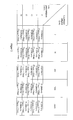
- eine Steuertabelle mit Wertepaaren (Umgebungshelligkeit und Fahrgeschwindigkeit) und den zugehörigen Bildwiederholraten bzw. Integrationszeiten,
- Figur 3
- eine dreidimensionales Diagramm zur Veranschaulichung der Steuertabelle gemäß Figur 2.
- (0 ≤ v < 5km/h) ^ (2 < L ≤ 20 Lux) => T= 67ms
- (5km/h ≤ v < 10 km/h) ^ (2 < L≤ 20 Lux) => T= 50ms
- (10km/h ≤ v < 15) ^ (2 < L≤ 20 Lux) => T= 40ms
- (15km/h ≤ v) ^ (2 < L≤ 20 Lux) => T= 33ms
- (0 ≤ v < 5km/h) ^ (20 < L≤ 200 Lux) => T= 50ms
- (5km/h ≤ v < 10 km/h) ^ (20 < L ≤ 200 Lux) => T= 40ms
- (10km/h ≤ v) ^ (2 < L ≤ 20 Lux) => T= 33ms
- (0 ≤ v < 5km/h) ^ (200 < L ≤ 2000 Lux) => T= 40ms
- (5km/h< v) ^ (200 < L ≤ 2000 Lux) => T= 33ms
- L > 2000 Lux => T=33ms
Claims (13)
- Optoelektronische Überwachungseinrichtung für Kraftfahrzeuge zur sequentiellen Aufnahme von Bildern der Kraftfahrzeugumgebung mit einem Sensorarray bestehend aus einer Vielzahl von einzelne Bildpunkte bildenden photoelektrischen Wandlerelementen, wobei die Wandlerelemente in Abhängigkeit von ihrer jeweiligen Lichtbeauschlagung ein der Lichtstärke und der elektronisch einstellbaren Integrationszeit entsprechendes elektrisches Signal generieren,
dadurch gekennzeichnet, dassdie Integrationszeit von mindestens einem Wandlerelement in Abhängigkeit von der Relativbewegung zwischen dem Kraftfahrzeug und der Umgebung eingestellt wird und/oderdie Integrationszeit in Abhängigkeit von der Relativbewegung von Objekten einer Bildfolge eingestellt wird. - Optoelektronische Überwachungseinrichtung nach Anspruch 1,
dadurch gekennzeichnet, dass
die Integrationszeit in Abhängigkeit von der Fahrgeschwindigkeit des Kraftfahrzeuges eingestellt wird. - Optoelektronische Überwachungseinrichtung nach Anspruch 1 oder 2,
dadurch gekennzeichnet, dass
die Integrationszeit in Abhängigkeit von der Relativbewegung von Objekten einer Bildfolge eingestellt wird. - Optoelektronische Überwachungseinrichtung nach einem der vorstehenden Ansprüche,
dadurch gekennzeichnet, dass
die Integrationszeit in Abhängigkeit von der Lichtstärke eingestellt wird. - Optoelektronische Überwachungsvorrichtung nach Anspruch 4,
dadurch gekennzeichnet, dass
das Signal mindestens eines Wandlerelements zur Bestimmung der Lichtstärke verwendet wird, um die Integrationszeit in Abhängigkeit der Lichtstärke einzustellen. - Optoelektronische Überwachungsvorrichtung nach Anspruch 5,
dadurch gekennzeichnet, dass
zur Bestimmung der Lichtstärke eine vorherbestimmte Anzahl von Wandlerelementen verwendet werden, die sich zueinander in einer definierten Position befinden. - Optoelektronische Überwachungsvorrichtung nach einem der Ansprüche 1 bis 4,
dadurch gekennzeichnet, dass
ein separater Lichtmesser zur Bestimmung der Lichtstärke verwendet wird, um die Integrationszeit in Abhängigkeit der Lichtstärke einzustellen. - Optoelektronische Überwachungseinrichtung nach einem der vorstehenden Ansprüche,
dadurch gekennzeichnet, dass
die Bildwiederholrate (Anzahl der Bilder, die pro Sekunde aufgenommen werden) in Abhängigkeit von der Fahrgeschwindigkeit eingestellt wird. - Optoelektronische Überwachungseinrichtung nach einem der vorstehenden Ansprüche,
dadurch gekennzeichnet, dass
ein elektronischer Speicher vorgesehen ist, in dem eine Steuertabelle abgespeichert ist, in der für verschiedene Wertepaare oder Wertebereichspaare bestehend aus Lichtstärke und Fahrgeschwindigkeit jeweils eine Integrationszeit definiert ist. - Optoelektronische Überwachungseinrichtung nach
einem der vorstehenden Ansprüche 1 bis 8,
dadurch gekennzeichnet, dass
in einer Ansteuereinheit ein Softwarealgorithmus implementiert ist, der die Integrationszeit in Abhängigkeit von der Lichtstärke und der Fahrgeschwindigkeit ermittelt. - Optoelektronische Überwachungseinrichtung nach einem der vorstehenden Ansprüche,
dadurch gekennzeichnet, dass
die Integrationszeit jeweils für sämtliche Wandlerelemente des Sensorarrays eingestellt wird. - Optoelektronische Überwachungseinrichtung nach
einem der vorstehenden Ansprüche 1 bis 10,
dadurch gekennzeichnet, dass
die Integrationszeit jeweils für eine Zeile oder eine Spalte von Wandlerelementen des Sensorarrays eingestellt wird. - Optoelektronische Überwachungseinrichtung nach einem der vorstehenden Ansprüche,
dadurch gekennzeichnet, dass
die aufgenommenen Bilder auf einem Monitor dargestellt werden, wobei die Bildausgaberäte zur Ausgabe der Bilder auf den Monitor höher ist als die Bildwiederholrate für die Aufnahme der Bilder.
Applications Claiming Priority (2)
| Application Number | Priority Date | Filing Date | Title |
|---|---|---|---|
| DE10342388A DE10342388A1 (de) | 2003-09-13 | 2003-09-13 | Optoelektronische Überwachungseinrichtung für Kraftfahrzeuge |
| DE10342388 | 2003-09-13 |
Publications (3)
| Publication Number | Publication Date |
|---|---|
| EP1515547A2 true EP1515547A2 (de) | 2005-03-16 |
| EP1515547A3 EP1515547A3 (de) | 2005-04-27 |
| EP1515547B1 EP1515547B1 (de) | 2006-11-02 |
Family
ID=34129796
Family Applications (1)
| Application Number | Title | Priority Date | Filing Date |
|---|---|---|---|
| EP04021290A Expired - Lifetime EP1515547B1 (de) | 2003-09-13 | 2004-09-08 | Optoelektronische Überwachungseinrichtung für Kraftfahrzeuge |
Country Status (2)
| Country | Link |
|---|---|
| EP (1) | EP1515547B1 (de) |
| DE (2) | DE10342388A1 (de) |
Cited By (2)
| Publication number | Priority date | Publication date | Assignee | Title |
|---|---|---|---|---|
| WO2009118057A1 (de) | 2008-03-26 | 2009-10-01 | Robert Bosch Gmbh | Bildaufnahmesystem für ein fahrzeug, fahrzeug, steuereinrichtung und verfahren zur regelung eines bildsensors eines fahrzeugs |
| US10228699B2 (en) | 2015-05-21 | 2019-03-12 | Denso Corporation | Image generation apparatus |
Families Citing this family (3)
| Publication number | Priority date | Publication date | Assignee | Title |
|---|---|---|---|---|
| DE102008005064B4 (de) * | 2008-01-18 | 2010-06-17 | Sick Ag | Optoelektronisches Detektionsverfahren und optoelektronischer Detektor |
| DE102013214369B4 (de) * | 2013-07-23 | 2021-03-04 | Application Solutions (Electronics and Vision) Ltd. | Verfahren und Vorrichtung zur Wiedergabe eines Umgebungsbereichs eines Fahrzeugs |
| DE102017212175A1 (de) | 2017-07-17 | 2019-01-17 | Robert Bosch Gmbh | Verfahren und Vorrichtung zum Ermitteln eines optischen Flusses anhand einer von einer Kamera eines Fahrzeugs aufgenommenen Bildsequenz |
Family Cites Families (11)
| Publication number | Priority date | Publication date | Assignee | Title |
|---|---|---|---|---|
| US4382267A (en) * | 1981-09-24 | 1983-05-03 | Rca Corporation | Digital control of number of effective rows of two-dimensional charge-transfer imager array |
| GB2219881A (en) * | 1988-06-15 | 1989-12-20 | English Electric Valve Co Ltd | Vehicle monitoring system |
| DE3909394A1 (de) * | 1989-03-22 | 1990-09-27 | Messerschmitt Boelkow Blohm | Zweidimensionaler ccd-bildsensor, bildaufnahmeverfahren fuer eine bewegte szene sowie ansteuerungsvorrichtung und -verfahren fuer den bildsensor |
| FR2665600A1 (fr) * | 1990-08-03 | 1992-02-07 | Thomson Csf | Procede de detection pour camera panoramique, camera pour sa mise en óoeuvre, et systeme de veille equipe d'une telle camera. |
| US5835137A (en) * | 1995-06-21 | 1998-11-10 | Eastman Kodak Company | Method and system for compensating for motion during imaging |
| JPH10175478A (ja) * | 1996-12-18 | 1998-06-30 | Koito Mfg Co Ltd | 車輌用灯具装置 |
| US5923027A (en) * | 1997-09-16 | 1999-07-13 | Gentex Corporation | Moisture sensor and windshield fog detector using an image sensor |
| US5837994C1 (en) * | 1997-04-02 | 2001-10-16 | Gentex Corp | Control system to automatically dim vehicle head lamps |
| CA2320153A1 (en) * | 1997-12-31 | 1999-07-08 | Gentex Corporation | Vehicle vision system |
| EP1110381B1 (de) * | 1998-08-28 | 2003-07-16 | Sarnoff Corporation | Gerät und verfahren zur elektronischen bildverbesserung |
| JP4108314B2 (ja) * | 2001-10-31 | 2008-06-25 | トヨタ自動車株式会社 | 車両用周辺監視装置 |
-
2003
- 2003-09-13 DE DE10342388A patent/DE10342388A1/de not_active Withdrawn
-
2004
- 2004-09-08 DE DE502004001886T patent/DE502004001886D1/de not_active Expired - Lifetime
- 2004-09-08 EP EP04021290A patent/EP1515547B1/de not_active Expired - Lifetime
Cited By (3)
| Publication number | Priority date | Publication date | Assignee | Title |
|---|---|---|---|---|
| WO2009118057A1 (de) | 2008-03-26 | 2009-10-01 | Robert Bosch Gmbh | Bildaufnahmesystem für ein fahrzeug, fahrzeug, steuereinrichtung und verfahren zur regelung eines bildsensors eines fahrzeugs |
| DE102008000819B4 (de) | 2008-03-26 | 2018-12-27 | Robert Bosch Gmbh | Steuereinrichtung zur Steuerung eines Bildsensors, Bildaufnahmesystem und Verfahren zur Regelung eines Bildsensors eines Fahrzeugs |
| US10228699B2 (en) | 2015-05-21 | 2019-03-12 | Denso Corporation | Image generation apparatus |
Also Published As
| Publication number | Publication date |
|---|---|
| EP1515547A3 (de) | 2005-04-27 |
| DE10342388A1 (de) | 2005-04-07 |
| DE502004001886D1 (de) | 2006-12-14 |
| EP1515547B1 (de) | 2006-11-02 |
Similar Documents
| Publication | Publication Date | Title |
|---|---|---|
| DE102004043257B4 (de) | Kameraeinheit und Vorrichtung zur Überwachung der Fahrzeugumgebung | |
| DE10152883B4 (de) | Nachführvorrichtung | |
| EP2765031B1 (de) | Sichtsystem für Fahrzeuge, insbesondere Nutzfahrzeuge | |
| DE3830695C2 (de) | ||
| EP3501897A1 (de) | Sichtsystem zur erfassung einer fahrzeugumgebung | |
| EP2431226A1 (de) | Rückblickeinrichtung für ein Kraftfahrzeug | |
| EP3882080A1 (de) | Sichtsystem für ein fahrzeug und verfahren zum umschalten zwischen von dem sichtsystem dargestellten bildbereichen | |
| DE69401792T2 (de) | Automatische Scheinwerfereinstellung zur Korrektur des Einflusses der Neigungsveränderung des Lichtbündels relativ zur Strasse | |
| DE102008061760A1 (de) | Vorrichtung zur Überwachung einer Umgebung eines Fahrzeugs | |
| DE102018207388B4 (de) | Verfahren und Vorrichtung zur Erzeugung eines Anzeigebildes in einem Kraftfahrzeug | |
| DE102004010908B4 (de) | Bildaufnahmevorrichtung und Bildaufnahmeverfahren | |
| DE102022207163B4 (de) | Anzeigevorrichtung eines Fahrzeugs und Verfahren zu deren Betrieb | |
| EP3677019B1 (de) | Verfahren und vorrichtung zur vorhersehbaren belichtungssteuerung zumindest einer ersten fahrzeugkamera | |
| EP1372111A2 (de) | Automobiles Infrarot-Nachtsichtgerät und automobiles Display | |
| EP2539866B1 (de) | Verfahren und vorrichtung zur freisichtprüfung einer kamera für ein automobiles umfeld | |
| WO2007098974A2 (de) | Vorrichtung und verfahren zur ausgabe von unterschiedlichen bildern auf wenigstens zwei anzeigen | |
| DE102016012341A1 (de) | Fahrerassistenzsystem für ein Kraftfahrzeug mit einer belichtungskompensierten Kamera | |
| DE102006009566A1 (de) | Verfahren und Vorrichtung zur Verhinderung von Kinetose-Störungen bei Passagieren von Kraftfahrzeugen | |
| DE102011114059A1 (de) | Vorrichtung und Verfahren zur Anzeige von Bewegtbildern in einem Kraftfahrzeug sowie Kraftfahrzeug | |
| EP1515547B1 (de) | Optoelektronische Überwachungseinrichtung für Kraftfahrzeuge | |
| DE102011076795A1 (de) | Verfahren zum Bestimmen einer Nickbewegung einer in einem Fahrzeug verbauten Kamera und Verfahren zur Steuerung einer Lichtaussendung zumindest eines Frontscheinwerfers eines Fahrzeugs | |
| EP3645343B1 (de) | Kameravorrichtung sowie verfahren zur umgebungsangepassten erfassung eines umgebungsbereichs eines fahrzeugs | |
| DE10016184A1 (de) | Vorrichtung zur Anzeige der Umgebung eines Fahrzeugs | |
| DE102013220022B4 (de) | Fahrzeugkamera zur Erfassung von Bildern aus einem Umgebungsbereich eines Fahrzeugs und Fahrzeug | |
| DE102015119871A1 (de) | Verfahren zum Betreiben eines Kamerasystems mit einer Vielzahl von Bildsensorelementen und Kraftfahrzeug |
Legal Events
| Date | Code | Title | Description |
|---|---|---|---|
| PUAI | Public reference made under article 153(3) epc to a published international application that has entered the european phase |
Free format text: ORIGINAL CODE: 0009012 |
|
| PUAL | Search report despatched |
Free format text: ORIGINAL CODE: 0009013 |
|
| AK | Designated contracting states |
Kind code of ref document: A2 Designated state(s): AT BE BG CH CY CZ DE DK EE ES FI FR GB GR HU IE IT LI LU MC NL PL PT RO SE SI SK TR |
|
| AX | Request for extension of the european patent |
Extension state: AL HR LT LV MK |
|
| RIC1 | Information provided on ipc code assigned before grant |
Ipc: 7B 60Q 1/08 B Ipc: 7G 08G 1/16 B Ipc: 7G 08G 1/04 B Ipc: 7G 06T 7/20 B Ipc: 7B 60Q 1/52 B Ipc: 7B 60R 1/00 B Ipc: 7H 04N 5/235 A |
|
| AK | Designated contracting states |
Kind code of ref document: A3 Designated state(s): AT BE BG CH CY CZ DE DK EE ES FI FR GB GR HU IE IT LI LU MC NL PL PT RO SE SI SK TR |
|
| AX | Request for extension of the european patent |
Extension state: AL HR LT LV MK |
|
| 17P | Request for examination filed |
Effective date: 20050929 |
|
| AKX | Designation fees paid |
Designated state(s): DE ES FR GB IT SE |
|
| GRAP | Despatch of communication of intention to grant a patent |
Free format text: ORIGINAL CODE: EPIDOSNIGR1 |
|
| GRAS | Grant fee paid |
Free format text: ORIGINAL CODE: EPIDOSNIGR3 |
|
| GRAA | (expected) grant |
Free format text: ORIGINAL CODE: 0009210 |
|
| AK | Designated contracting states |
Kind code of ref document: B1 Designated state(s): DE FR GB SE |
|
| REG | Reference to a national code |
Ref country code: GB Ref legal event code: FG4D Free format text: NOT ENGLISH |
|
| REF | Corresponds to: |
Ref document number: 502004001886 Country of ref document: DE Date of ref document: 20061214 Kind code of ref document: P |
|
| GBT | Gb: translation of ep patent filed (gb section 77(6)(a)/1977) |
Effective date: 20061220 |
|
| PG25 | Lapsed in a contracting state [announced via postgrant information from national office to epo] |
Ref country code: SE Free format text: LAPSE BECAUSE OF FAILURE TO SUBMIT A TRANSLATION OF THE DESCRIPTION OR TO PAY THE FEE WITHIN THE PRESCRIBED TIME-LIMIT Effective date: 20070202 |
|
| ET | Fr: translation filed | ||
| PLBE | No opposition filed within time limit |
Free format text: ORIGINAL CODE: 0009261 |
|
| STAA | Information on the status of an ep patent application or granted ep patent |
Free format text: STATUS: NO OPPOSITION FILED WITHIN TIME LIMIT |
|
| 26N | No opposition filed |
Effective date: 20070803 |
|
| PGFP | Annual fee paid to national office [announced via postgrant information from national office to epo] |
Ref country code: DE Payment date: 20110831 Year of fee payment: 8 Ref country code: GB Payment date: 20110907 Year of fee payment: 8 Ref country code: FR Payment date: 20110922 Year of fee payment: 8 |
|
| GBPC | Gb: european patent ceased through non-payment of renewal fee |
Effective date: 20120908 |
|
| REG | Reference to a national code |
Ref country code: FR Ref legal event code: ST Effective date: 20130531 |
|
| PG25 | Lapsed in a contracting state [announced via postgrant information from national office to epo] |
Ref country code: DE Free format text: LAPSE BECAUSE OF NON-PAYMENT OF DUE FEES Effective date: 20130403 Ref country code: GB Free format text: LAPSE BECAUSE OF NON-PAYMENT OF DUE FEES Effective date: 20120908 |
|
| PG25 | Lapsed in a contracting state [announced via postgrant information from national office to epo] |
Ref country code: FR Free format text: LAPSE BECAUSE OF NON-PAYMENT OF DUE FEES Effective date: 20121001 |
|
| REG | Reference to a national code |
Ref country code: DE Ref legal event code: R119 Ref document number: 502004001886 Country of ref document: DE Effective date: 20130403 |