EP1515546A2 - Videobenutzerschnittstellensystem und -verfahren - Google Patents
Videobenutzerschnittstellensystem und -verfahren Download PDFInfo
- Publication number
- EP1515546A2 EP1515546A2 EP04010139A EP04010139A EP1515546A2 EP 1515546 A2 EP1515546 A2 EP 1515546A2 EP 04010139 A EP04010139 A EP 04010139A EP 04010139 A EP04010139 A EP 04010139A EP 1515546 A2 EP1515546 A2 EP 1515546A2
- Authority
- EP
- European Patent Office
- Prior art keywords
- view
- data
- panoramic
- virtual
- virtual view
- Prior art date
- Legal status (The legal status is an assumption and is not a legal conclusion. Google has not performed a legal analysis and makes no representation as to the accuracy of the status listed.)
- Granted
Links
Images


Classifications
-
- H—ELECTRICITY
- H04—ELECTRIC COMMUNICATION TECHNIQUE
- H04N—PICTORIAL COMMUNICATION, e.g. TELEVISION
- H04N23/00—Cameras or camera modules comprising electronic image sensors; Control thereof
- H04N23/60—Control of cameras or camera modules
- H04N23/698—Control of cameras or camera modules for achieving an enlarged field of view, e.g. panoramic image capture
-
- G—PHYSICS
- G06—COMPUTING OR CALCULATING; COUNTING
- G06F—ELECTRIC DIGITAL DATA PROCESSING
- G06F3/00—Input arrangements for transferring data to be processed into a form capable of being handled by the computer; Output arrangements for transferring data from processing unit to output unit, e.g. interface arrangements
- G06F3/01—Input arrangements or combined input and output arrangements for interaction between user and computer
- G06F3/048—Interaction techniques based on graphical user interfaces [GUI]
- G06F3/0481—Interaction techniques based on graphical user interfaces [GUI] based on specific properties of the displayed interaction object or a metaphor-based environment, e.g. interaction with desktop elements like windows or icons, or assisted by a cursor's changing behaviour or appearance
- G06F3/04815—Interaction with a metaphor-based environment or interaction object displayed as three-dimensional [3D], e.g. changing the user viewpoint with respect to the environment or object
-
- G—PHYSICS
- G08—SIGNALLING
- G08B—SIGNALLING SYSTEMS, e.g. PERSONAL CALLING SYSTEMS; ORDER TELEGRAPHS; ALARM SYSTEMS
- G08B13/00—Burglar, theft or intruder alarms
- G08B13/18—Actuation by interference with heat, light, or radiation of shorter wavelength; Actuation by intruding sources of heat, light, or radiation of shorter wavelength
- G08B13/189—Actuation by interference with heat, light, or radiation of shorter wavelength; Actuation by intruding sources of heat, light, or radiation of shorter wavelength using passive radiation detection systems
- G08B13/194—Actuation by interference with heat, light, or radiation of shorter wavelength; Actuation by intruding sources of heat, light, or radiation of shorter wavelength using passive radiation detection systems using image scanning and comparing systems
- G08B13/196—Actuation by interference with heat, light, or radiation of shorter wavelength; Actuation by intruding sources of heat, light, or radiation of shorter wavelength using passive radiation detection systems using image scanning and comparing systems using television cameras
- G08B13/19617—Surveillance camera constructional details
- G08B13/19626—Surveillance camera constructional details optical details, e.g. lenses, mirrors or multiple lenses
- G08B13/19628—Surveillance camera constructional details optical details, e.g. lenses, mirrors or multiple lenses of wide angled cameras and camera groups, e.g. omni-directional cameras, fish eye, single units having multiple cameras achieving a wide angle view
-
- G—PHYSICS
- G08—SIGNALLING
- G08B—SIGNALLING SYSTEMS, e.g. PERSONAL CALLING SYSTEMS; ORDER TELEGRAPHS; ALARM SYSTEMS
- G08B13/00—Burglar, theft or intruder alarms
- G08B13/18—Actuation by interference with heat, light, or radiation of shorter wavelength; Actuation by intruding sources of heat, light, or radiation of shorter wavelength
- G08B13/189—Actuation by interference with heat, light, or radiation of shorter wavelength; Actuation by intruding sources of heat, light, or radiation of shorter wavelength using passive radiation detection systems
- G08B13/194—Actuation by interference with heat, light, or radiation of shorter wavelength; Actuation by intruding sources of heat, light, or radiation of shorter wavelength using passive radiation detection systems using image scanning and comparing systems
- G08B13/196—Actuation by interference with heat, light, or radiation of shorter wavelength; Actuation by intruding sources of heat, light, or radiation of shorter wavelength using passive radiation detection systems using image scanning and comparing systems using television cameras
- G08B13/19678—User interface
- G08B13/19682—Graphic User Interface [GUI] presenting system data to the user, e.g. information on a screen helping a user interacting with an alarm system
-
- G—PHYSICS
- G08—SIGNALLING
- G08B—SIGNALLING SYSTEMS, e.g. PERSONAL CALLING SYSTEMS; ORDER TELEGRAPHS; ALARM SYSTEMS
- G08B13/00—Burglar, theft or intruder alarms
- G08B13/18—Actuation by interference with heat, light, or radiation of shorter wavelength; Actuation by intruding sources of heat, light, or radiation of shorter wavelength
- G08B13/189—Actuation by interference with heat, light, or radiation of shorter wavelength; Actuation by intruding sources of heat, light, or radiation of shorter wavelength using passive radiation detection systems
- G08B13/194—Actuation by interference with heat, light, or radiation of shorter wavelength; Actuation by intruding sources of heat, light, or radiation of shorter wavelength using passive radiation detection systems using image scanning and comparing systems
- G08B13/196—Actuation by interference with heat, light, or radiation of shorter wavelength; Actuation by intruding sources of heat, light, or radiation of shorter wavelength using passive radiation detection systems using image scanning and comparing systems using television cameras
- G08B13/19678—User interface
- G08B13/19689—Remote control of cameras, e.g. remote orientation or image zooming control for a PTZ camera
-
- G—PHYSICS
- G08—SIGNALLING
- G08B—SIGNALLING SYSTEMS, e.g. PERSONAL CALLING SYSTEMS; ORDER TELEGRAPHS; ALARM SYSTEMS
- G08B13/00—Burglar, theft or intruder alarms
- G08B13/18—Actuation by interference with heat, light, or radiation of shorter wavelength; Actuation by intruding sources of heat, light, or radiation of shorter wavelength
- G08B13/189—Actuation by interference with heat, light, or radiation of shorter wavelength; Actuation by intruding sources of heat, light, or radiation of shorter wavelength using passive radiation detection systems
- G08B13/194—Actuation by interference with heat, light, or radiation of shorter wavelength; Actuation by intruding sources of heat, light, or radiation of shorter wavelength using passive radiation detection systems using image scanning and comparing systems
- G08B13/196—Actuation by interference with heat, light, or radiation of shorter wavelength; Actuation by intruding sources of heat, light, or radiation of shorter wavelength using passive radiation detection systems using image scanning and comparing systems using television cameras
- G08B13/19678—User interface
- G08B13/19691—Signalling events for better perception by user, e.g. indicating alarms by making display brighter, adding text, creating a sound
-
- H—ELECTRICITY
- H04—ELECTRIC COMMUNICATION TECHNIQUE
- H04N—PICTORIAL COMMUNICATION, e.g. TELEVISION
- H04N23/00—Cameras or camera modules comprising electronic image sensors; Control thereof
- H04N23/60—Control of cameras or camera modules
- H04N23/62—Control of parameters via user interfaces
-
- H—ELECTRICITY
- H04—ELECTRIC COMMUNICATION TECHNIQUE
- H04N—PICTORIAL COMMUNICATION, e.g. TELEVISION
- H04N23/00—Cameras or camera modules comprising electronic image sensors; Control thereof
- H04N23/60—Control of cameras or camera modules
- H04N23/63—Control of cameras or camera modules by using electronic viewfinders
- H04N23/633—Control of cameras or camera modules by using electronic viewfinders for displaying additional information relating to control or operation of the camera
- H04N23/635—Region indicators; Field of view indicators
-
- H—ELECTRICITY
- H04—ELECTRIC COMMUNICATION TECHNIQUE
- H04N—PICTORIAL COMMUNICATION, e.g. TELEVISION
- H04N7/00—Television systems
- H04N7/18—Closed-circuit television [CCTV] systems, i.e. systems in which the video signal is not broadcast
- H04N7/181—Closed-circuit television [CCTV] systems, i.e. systems in which the video signal is not broadcast for receiving images from a plurality of remote sources
-
- H—ELECTRICITY
- H04—ELECTRIC COMMUNICATION TECHNIQUE
- H04N—PICTORIAL COMMUNICATION, e.g. TELEVISION
- H04N23/00—Cameras or camera modules comprising electronic image sensors; Control thereof
- H04N23/60—Control of cameras or camera modules
- H04N23/695—Control of camera direction for changing a field of view, e.g. pan, tilt or based on tracking of objects
Definitions
- This invention generally relates to imaging systems, and more particularly, to a system and method for generating a graphical user interface from image data, such as video images.
- Conventional video surveillance systems allow users to view portions of monitored areas by either physically aiming a video camera at a desired portion or by generating a perspective corrected view of the desired portion from a wide angle (e.g., fisheye) image of the monitored area.
- a video surveillance system may display a close-up image of a person or an object (the displayed portion) in a room or a parking lot (the monitored area). Without an image of the entire room or lot and an indication of the area represented by the close-up image, it may be difficult or impossible to quickly determine the position of the person or object in the monitored room or lot. This is especially true for a crowded room or lot, where it may be difficult to distinguish one isolated portion from another.
- video surveillance systems typically do not allow an operator to see anything but the portions of monitored areas being displayed.
- the undisplayed portions may comprise a substantial portion of a monitored area, in which significant activity of interest may occur. For example, if a displayed image represents only 10% of a monitored parking lot, the other 90% may be unmonitored at any given time.
- the invention overcomes one or more of the problems in conventional video surveillance systems as set forth above, it should be apparent that the invention may have applicability to a wide array of imaging devices and methods, particularly those employing images of moving objects, regardless of the particular format of the image data.
- the invention avoids the drawbacks of the prior art by providing a graphical user interface that may, according to one aspect of the invention, include one or more panoramic views of a monitored area, one or more virtual views preferably corresponding to portions of the monitored area, and/or reference data such as a reference window overlaid in a panoramic view to identify a portion of the panoramic view corresponding to a virtual view.
- Panoramic views of the invention which may be derived from wide-angle lens image data, exhibit a determined (e.g., upright) orientation and substantially reduced (or no) wide-angle image distortion, thus providing a readily discernible view.
- Virtual views of the invention which may be based upon either transformed wide-angle lens image data or image data from a camera system without a wide-angle lens, also exhibit substantially reduced (or no) wide-angle image distortion, thus providing a readily discernible view.
- the virtual views and reference windows may respond to operator commands.
- a system for creating signals indicative of a graphical user interface from wide-angle image data, such as video images, corresponding to a monitored area.
- the system includes a buffer configured to receive wide-angle image data such as video images, corresponding to the monitored area.
- a processor operably coupled to the buffer is configured to transform wide angle image data received by the buffer into panoramic view data corresponding to at least one panoramic view of the monitored area, and into virtual view data corresponding to at least one virtual view of a portion of the at least one panoramic view.
- a method of creating a graphical user interface includes the steps of buffering wide-angle data corresponding to a wide-angle image, such as a video image, of a monitored area; transforming the buffered data into panoramic data for at least one panoramic view using a panoramic transformation; and transforming portions of the buffered data into virtual view data for at least one virtual view using a virtual view transformation.
- the graphical user interface may include a reference window overlaid in a panoramic view to identify a portion of the panoramic view represented by a virtual view.
- the system may include a dome camera system configured to provide image data for a virtual view according to commands. The dome camera image data may exhibit higher resolution than the wide-angle data.
- a system for creating signals indicative of a graphical user interface from wide-angle image data corresponding to a monitored area includes a means for storing wide-angle image data corresponding to a monitored area.
- the system also includes a means for processing and transforming data received from said storing means into panoramic view data corresponding to at least one panoramic view of the monitored area and into virtual view data corresponding to at least one virtual view of a portion of the at least one panoramic view.
- An exemplary system in accordance with the invention includes a processor configured to transform digital image data corresponding to the wide-angle images, such as video images, of a monitored area into data corresponding to one or more panoramic views of the monitored area.
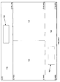
- a user interface in accordance with an exemplary implementation of the invention is conceptually shown.
- Strips 110 and 160 which may be rectangular in shape as illustrated, correspond to transformed panoramic views.
- the transformed panoramic views 110 and 160 exhibit upright orientation and substantially reduced (or no) wide-angle image distortion, thus providing a readily discernible view of the monitored area. Examples of a suitable transformation carried out by the processor are discussed subsequently.
- the processor is also configured to provide data corresponding to one or more virtual views 130 and 140 , each of which is an undistorted (or substantially undistorted) view of a user-determined portion of the panoramic views 110 and 160 .
- Virtual view data may be obtained either by transformation of portions of the wide-angle video image data, or by positioning and focusing a camera having a normal lens (i.e., not a wide angle lens) or a telephoto lens to produce image data for the determined portion of the monitored area. Again, a suitable transformation to obtain the virtual view data is discussed subsequently.
- the processor may be further configured to provide reference data (e.g., windows - i.e., graphically generated boxes or other shapes overlaid in the panoramic views - boxes 120 and 150 as shown in Figure 1 ) corresponding to the undistorted view of the determined portions of the panoramic views represented by the virtual views 130 and 140 .
- reference data e.g., windows - i.e., graphically generated boxes or other shapes overlaid in the panoramic views - boxes 120 and 150 as shown in Figure 1
- the reference data 120 and 150 reveals what portions of the panoramic views are represented by the virtual views 130 and 140 .
- the corresponding reference window 120 or 150 overlaid on top of a panoramic view 110 and 160 moves in the panoramic view 110 or 160 , thus indicating the part of the panoramic view 110 and 160 represented by the virtual view 130 or 140 .
- the system is preferably configured to allow a user to select which virtual view 130 or 140 to currently control.
- the active (i.e., currently controlled) virtual view 130 or 140 may be distinguished from the inactive virtual view by an indicia. For example, a white frame may surround the active virtual window and a black frame may surround the inactive virtual view.
- the corresponding reference window 120 or 150 may also be highlighted in either black or white based on its associated virtual view's active/inactive status.
- the exemplary display screen may have a resolution of 486 by 720 pixels.
- the exemplary panoramic views, as shown in Figure 1 are each 720 pixels wide and 120 pixels high.
- the exemplary virtual views, as shown in Figure 1 may each be 360 pixels wide and 246 pixels high.
- Those skilled in the art will appreciate that the invention is not limited to the exemplary resolution or view sizes. Many other resolutions and sizes are feasible and come within the scope of the invention.
- the reference data may be controllable via a user input device, such as a joystick, cursors or other pointing device.
- a user may move and resize reference windows 120 and 150 to cover any portions of the panoramic views 110 and 160 .
- the portions of the panoramic views covered by the reference windows 120 and 150 correspond to or define the virtual views 130 and 140 .
- the system may also automatically determine the portions of the panoramic views 110 and 160 to cover, such as by one or more determined algorithms (e.g., move reference windows as a function of time) or in response to one or more signals (e.g., a motion detector, gate sensor, or alarm signal).
- Other manifestations of reference data such as numerical coordinates or cross hairs, may be used in lieu of or in addition to reference windows 120 and 150.
- Panoramic views 110 and 160 and virtual views 130 and 140 may be displayed concurrently on a display monitor, thus providing a readily discernible view of the entire monitored area and an undistorted (or substantially undistorted) view of a portion of the monitored area.
- the reference data 120 and 150 may also be displayed with the panoramic views 110 and 160 , thus enabling a user to readily identify the portions of the panoramic views 110 and 160 that are represented by the virtual views 130 and 140 .
- the invention is not limited to the exemplary number, size, shape or arrangement of panoramic views and/or reference windows shown in Figure 1 and discussed above.
- one or more panoramic views 110 and 160 , virtual views 130 and 140 and or reference windows 120 and 150 may be provided without departing from the scope of the invention.
- the user interface components may be arranged as shown in Figure 1 and discussed above, or differently, on one or more display monitors, or in one or more windowed portions of one or more display monitors, without departing from the scope of the invention.
- the interface may be configured to allow a user to control the display arrangement.
- a user may hide or move a panoramic view 110 or 160 , and/or a virtual view 130 or 140 and/or a reference window 120 or 150 ; or hide all virtual views 130 and 140 reference windows 120 and 150 ; or opt to display only a selected panoramic view 110 or 160 or virtual view 130 or 140.
- image sources may supply image data for use by a system in accordance with the invention.
- one or more imagers such as digital or analog video cameras may be used to supply video data, which may be in any known format.
- video broadly refers to images, such as images of stationary and/or moving objects, which may or may not be produced using signals in standard formats, such as NTSC signals.
- the system of the invention may operate in real time, processing video data as it is produced using the video imagers and without appreciably delaying output to a display monitor or recorder.
- saved analog or digital video signals or data may serve as the source of images.
- the video imaging system 200 includes a video camera 210 equipped with a wide-angle lens 205 , such as a fisheye lens.
- a wide-angle lens 205 such as a fisheye lens.
- Various wide-angle lenses are available, many of which, for example, have an angular field of view of approximately 50 degrees or more.
- the wide-angle lens may preferably be suitable for producing an image of an entire area to be monitored (e.g., portions of a room excluding the ceiling) when the wide-angle lens is positioned at a determined point relative to the monitored area (e.g., on a ceiling of the room, at or near the center of the ceiling, pointing downwardly).
- a fisheye lens which is a type of wide-angle lens, and which may have a field of view of 180 degrees
- the camera 210 may be a digital camera such as a camera that employs a charge coupled device (CCD) array, a Time Delay Integration (TDI) CCD array, complementary metal oxide semiconductor (CMOS) image sensors or other sensors or devices for electronic image production.
- the camera 210 may be an analog camera that produces analog (e.g. NTSC or PAL) output signals.
- the wide-angle lens 205 is aimed at the area to be monitored.
- the lens 205 may be a fisheye lens or another type of wide-angle lens that provides a 180° field of view, or a wider or narrower field of view.
- the position and orientation may generate a fisheye view of the entire monitored area.
- a video decoder 215 operably coupled to the camera translates analog signals from the camera into digital video data.
- the decoder 215 may include a clock circuit (e.g., a 27 MHz video clock circuit) suitable for synchronization and processing of video image data streams.
- Clock signals 217 from the clock circuit may be transmitted to processor 225 .
- a suitable decoder 215 may include commercially available decoders, such as an SAA7113H 9-bit video input processor available from Phillips Electronics N.V.
- the SAA7113H 9-bit video input processor includes an anti-aliasing filter, an automatic clamp and gain control, a clock generation circuit, a digital multi-standard decoder, and a brightness, contrast and saturation control circuit. It is able to decode Phase Alternation Line (PAL), French Sequential Couleur Electro Memoire (SECAM) and American National Television Systems Committee (NTSC) standard signals into CCIR-601 (International Radio Consultative Committee, now the International Telecommunication Union Radiocommunication Sector, standard for encoding analog video signals in digital form) compatible color component data values.
- the SAA7113H accepts as analog inputs CVBS (i.e., composite Chroma Video Blanking & Sync inputs) or S-video (Y/C).
- Digital video data from decoder 215 may be stored in an image buffer 220 .
- the image buffer 220 provides a means for storing wide-angle image data corresponding to a monitored area.
- the image buffer 220 may be comprised of volatile or non-volatile memory or other devices configured to store video image data.
- the data may be stored temporarily, for example, until no longer needed for transformation by the image data processor 225 , as described below, until new video image data is required to be stored in the occupied portion of the buffer, or until some other event occurs or a period of time elapses.
- the buffer 220 may be sized to store image data corresponding to an entire field or frame of video, or more or less data.
- One or more user input modules 290 may also be provided to generate user commands.
- the module may include an input device 275 such as a keypad, digitizer, joystick, microphone and voice recognition module, or some other device configured to enable a user to enter commands.
- the input device 275 may be operably coupled to an input processor 280 and input memory 285 configured to produce user command data 292 corresponding to user input commands.
- the input processor 280 may be implemented as a special purpose computer; a programmed general purpose computer; a programmed microprocessor, microcontroller or programmable read-only memory and peripheral integrated circuit elements; an application specific integrated circuit (ASIC) or other integrated circuits; a digital signal processor; a hardwired electronic or logic circuit such as a discrete element circuit; a programmable logic device such as a field programmable gate array (FPGA), or the like.
- ASIC application specific integrated circuit
- FPGA field programmable gate array
- the input memory 285 may include volatile or non-volatile memory such as, for example, static random access memory (SRAM), dynamic random access memory (DRAM), fast page mode dynamic random access memory (FPM DRAM), extended data-out dynamic random access memory (EDO DRAM), synchronous dynamic random access memory (SDRAM), double data rate synchronous dynamic RAM (DDR SDRAM), electronically erasable programmable read only memory (EEPROM) such as flash memory with or without a controller, hard disk enabled virtual memory, and/or other data storage devices that may be operably coupled to the input processor 280 .
- SRAM static random access memory
- DRAM dynamic random access memory
- FPM DRAM fast page mode dynamic random access memory
- EEO DRAM extended data-out dynamic random access memory
- SDRAM synchronous dynamic random access memory
- DDR SDRAM double data rate synchronous dynamic RAM
- EEPROM electronically erasable programmable read only memory
- flash memory with or without a controller, hard disk enabled virtual memory, and/or other data storage devices that may be operably coupled to the
- An image data processor 225 may receive buffered image data 222 , clock signals 217 and user command data 292 to produce panoramic view data, virtual view data and reference data.
- the image data processor 225 thus provides a means for processing and transforming data received from the storing means (i.e., the image buffer 220 ) into panoramic view data corresponding to at least one panoramic view of the monitored area and into virtual view data corresponding to at least one virtual view of a portion of the at least one panoramic view.
- the processor 225 may be implemented as a special purpose computer; a programmed general purpose computer; a programmed microprocessor, microcontroller or programmable read-only memory and peripheral integrated circuit elements; an application specific integrated circuit (ASIC) or other integrated circuits; a digital signal processor; a hardwired electronic or logic circuit such as a discrete element circuit; a programmable logic device such as a field programmable gate array (FPGA), or the like.
- a preferred implementation uses an FPGA or an ASIC as the processor 225 . When a system design is considered stable, an FPGA could be replaced with an ASIC to reduce system cost.
- the image data processor 225 may also be operably coupled to memory 230 , which may, for example, be non-volatile memory in the form of electronically erasable programmable read only memory (EEPROM), such as flash memory, with or without a controller; a solid-state floppy-disk card (SSFDC) such as SmartMedia® memory commercially available from Kabushiki Kaisha Toshiba, Toshiba Corporation, and Toshiba America Electronic Components, Inc.; CompactFlash® memory by SanDisk Corporation; hard disk enabled virtual memory; and/or other non-volatile storage devices.
- memory 230 may be used to facilitate processor computations by storing one or more tables of values for frequently calculated functions, especially functions that might otherwise consume significant processor 225 resources.
- memory 230 may store a table of values, such as cosine, sine, 1/cosine, 1/sine, or other values based on trigonometric or other types of functions used in an applicable transformation algorithm, as discussed more fully below.
- the indices for the table may be angular values in degrees, radians, other types of measurements, or some other possible value for a variable.
- the table entries may be pre-calculated values based on the corresponding indices. Trigonometric functions and complex floating point calculations can otherwise be a time and resource consuming part of processor 225 calculations. The use of pre-determined stored values conserves processor resources and may lead to an appreciable increase in overall computation speed.
- the image data processor 225 mathematically transforms wide angle video image data in the image buffer 220 into panoramic views using a panoramic view transformation algorithm.
- the image data processor 225 may also transform wide angle video image data in the image buffer 220 into virtual views using a virtual view transformation algorithm, as discussed more fully below.
- the processor 225 Upon transformation, the processor 225 sends transformed video data to an encoder 235 .
- the encoder converts the digital video data into output signals compatible with an output device such as a display monitor 240 and/or video recorder 245 .
- the encoder may be any suitable commercially available decoder, such as an SAA7121H digital video encoder by Phillips Electronics, N.V.
- the SAA7121H digital video encoder circuit accepts CCIR compatible YUV data with 720 active pixels per line and encodes the digital YUV video data to NTSC, PAL, CVBS or S-video signals.
- Output from the encoder 235 is sent to an output device, such as a standard display monitor 240 and/or video recorder 245 .
- the display monitor may be any device configured to visually display images based on electronic video signals output from the encoder 235 .
- the recorder may be any device configured to record video signals from the encoder 235 on removable or non-removable storage media such as, for example, a magnetic tape, diskette, CD-ROM, DVD, hard disk, memory (e.g., nonvolatile EEPROM) or the like. If both a display monitor 240 and recorder 245 are used, the devices may be configured in parallel or in series (e.g., without output from the video recorder being sent to a display monitor).
- the image data processor 225 may generate virtual view data from video image data produced by a one or more additional camera systems 250 .
- An additional camera system may include an analog or digital camera 260 with a normal lens 255 (i.e., not a wide angle lens) aimed at a determined portion of the monitored area.
- the lens 255 may have a narrower Field of View ( FOV), e.g., 45°, which would provide higher resolution than wide-angle lens 205 , thus providing a more detailed video image for a virtual view.
- FOV Field of View
- the additional camera enables switching from a low resolution virtual view derived from wide-angle lens image data to a high resolution virtual view, with high zoom factor capability, produced using the additional camera system. This gives the user the ability to isolate small details of a monitored area.
- the additional camera system 250 may also include a video decoder 265 that is operably coupled to the camera and configured to translate analog signals from the camera into digital video data.
- the decoder 265 may also include a clock circuit (e.g., a 27 MHz video clock circuit) suitable for synchronization and processing of video image data streams.
- Clock signals 267 may be transmitted to processor 225 .
- the additional camera system 250 may further include an image buffer 270 .
- the image buffer 270 may be comprised of volatile or non-volatile memory or other devices configured to temporarily store video image data, such as, for example, static random access memory (SRAM), dynamic random access memory (DRAM), fast page mode dynamic random access memory (FPM DRAM), extended data-out dynamic random access memory (EDO DRAM), synchronous dynamic random access memory (SDRAM), double data rate synchronous dynamic RAM (DDR SDRAM), Rambus dynamic random access memory (RDRAM), multiport dynamic random access memory (MPDRAM), synchronous graphics RAM (SGRAM), electronically erasable programmable read only memory (EEPROM), hard disk enabled virtual memory and/or other data storage device.
- SRAM static random access memory
- DRAM dynamic random access memory
- FPM DRAM fast page mode dynamic random access memory
- EEO DRAM extended data-out dynamic random access memory
- SDRAM synchronous dynamic random access memory
- DDR SDRAM double data rate synchronous dynamic RAM
- RDRAM Rambus dynamic random access memory
- the buffer 270 may be sized to store image data corresponding to an entire field or frame of video, or more or less data. Buffered video data 272 may be transmitted to processor 225 . That data may then be processed and encoded 235 for display in either virtual view 130 or 140 .
- the additional camera system 250 may be configured as a programmable dome camera system. Dome cameras can typically rotate (i.e., pan) 360 degrees, and tilt and zoom according to control signals.
- the dome camera 260 may be coupled to a processor programmed to produce control signals causing the camera 260 to aim at particular portions of a monitored area in particular patterns.
- processor 225 may produce control data 294 , based upon user command data 292 from user input module 290 , to control positioning and movement of the dome camera.
- a control interface (not shown) may also be operably coupled to dome camera 260 and processor 225 , as necessary to convert control data output from the processor 225 into signals for controlling dome camera 260 position, movement and zooming.
- panoramic views 110 and 160 and virtual views 130 and 140 may be produced by transforming wide-angle image data (including fisheye image data) into 2-dimensional space, without distortion (or with substantially reduced distortion).
- Many such transformation processes also referred to as dewarping, mapping, remapping, planar projection, conversion and perspective correction
- panoramic views 110 and 160 and virtual views 130 and 140 with linear perspective geometry from wide-angle image data (including fisheye image data) are known in the art and can be adapted, in accordance with the teachings herein, to produce panoramic views 110 and 160 and virtual views 130 and 140 with linear perspective geometry from wide-angle image data (including fisheye image data).
- an exemplary panoramic view transformation and an exemplary virtual view transformation are described more fully below for use with a system of the invention employing fisheye lens image data.
- the panoramic view transformation process involves mathematically transforming wide angle video image data into 2-dimensional space for producing panoramic views.
- the exemplary transformation entails determining, for each output window pixel coordinate, an address within the image buffer 220 for pixel data to be encoded and output to a display 240 and/or recorder 245 .
- this address calculation is timed such that the calculated address for each output pixel is ready just in time to feed the output encoder. This implementation advantageously eliminates the need for an output image buffer.
- two panoramic views 110 and 160 are produced.
- One panoramic view 110 corresponds to half of the monitored area (e.g., a 0-180 degree panoramic view strip).
- the other panoramic view corresponds to the other half of the monitored area (e.g., a 181-360° panoramic view strip).
- the second panoramic view is offset from the first panoramic view by half of the field of view.
- the points dividing one half from the other half may be pre-programmed, user configurable or user controllable.
- the two panoramic views combined provide a full (e.g., a 360°) view of the monitored area.
- the exemplary panoramic views are 720 pixels wide and 120 pixels high.
- Output window pixel coordinates range from -360 to +360 for Wx and from -60 to +60 for Wy.
- the Wx and Wy coordinates are derived from the output view column and line pixel counters, and together with the desired Zoom factor, are transformed into ⁇ (i.e., the pan rotation angle around the Z-axis) and ⁇ (the tilt rotation angle around the X-axis), as conceptually illustrated in Figure 3 .
- This information is then converted to an address in the input capture buffer.
- the data from this address is output to the encoder for display.
- the variables Pan, Tilt and Zoom may be programmed or commanded via user input module 290 . Given:
- the horizontal component of the panoramic view (starting with output window upper left at - 360 ,+ 120 ) is converted from pixel units to degrees( SFx ). Each output pixel equates to .25 degrees ( 180° / 720 pixels). The programmable Pan value is added to each pixel value.
- the second panoramic view 160 is offset from the first 110 by + 180 degrees.
- the vertical component of the panoramic view (starting with output window upper left at origin -360,+120) is converted from pixel units to degrees (SFy). Each vertical pixel equates to 0.375 degrees (45°/120lines).
- the programmable Tilt value is added to each pixel value.
- the programmable zoom performs a scale (45° x (1/zoom)) / 120. Therefore, Zoom Scale equals 1.
- the image buffer 220 is preferably addressed as a 1024 byte by 1024 byte array.
- PixelData may then be sent to the encoder 235 for output to the output device such as a display monitor 240 and or a recorder 245 .
- Pixel Data for each pixel comprising the panoramic views 110 and 160 may be determined in a similar manner.
- Each virtual view window 130 and 140 provides a perspective corrected view (e.g., a view with no, or substantially reduced, fisheye distortion) of any portion of a panoramic view 110 or 160 .
- the virtual view windows are preferably 360 pixels wide and 240 pixels high. The center of the window is defined as 0,0.
- Wx values range from - 180 to + 180 and Wy values range from + 120 down to - 120.
- the Wx and Wy coordinates are taken from the output window line and pixel counters and, together with the desired Pan, Tilt and Zoom Scale, are transformed into ⁇ , ⁇ , and Radius using the virtual view transformation algorithm.
- the processor determines which algorithm (i.e., the virtual view transformation algorithm or the panoramic view transformation algorithm) to use based on where the counters indicate it is in the output video frame.
- ⁇ is defined as the Pan angle around the Z-Axis, where the positive Y direction, as shown in Figure 3, is 0 degrees.
- ⁇ is the Tilt angle around the X-Axis where the positive Z direction, pointing straight down as shown in Figure 3, is 0 degrees.
- Z is the perpendicular distance from the X-Y plane down to the surface of a unity radius hemispheric fisheye model.
- the virtual view transformation algorithm entails converting the X and Y output window coordinates to an equivalent proportion of a unity radius hemisphere model using a current Zoom factor and a measured radius-X and radius-Y from an input fisheye circular image. These adjusted values are used to calculate a corresponding Z value.
- the X, Y and Z coordinates are rotated around the unity radius hemisphere model using the commanded Pan and Tilt from the user input module 290.
- the rotated X and Y values are then rescaled back to pixels and lines, based on measured radius-X and radius-Y from the input fisheye circular image.
- the rescaled X and Y are then converted to an address in the input capture buffer. Data from this address is then output to the encoder for display.
- the variables Pan, Tilt, and Zoom are the angle of interest commanded by the user input module 290 . Given:
- a rotation of the desired window to a desired spot on the image can be performed using the Pan and Tilt values to simulate a movable dome.
- Wy' ( Wy ⁇ cos( Tilt )) + ( Iz ⁇ sin( Tilt ))
- Wy' ( Wx ⁇ sin( Pan )) + ( Wy' ⁇ cos( Pan ))
- Equation 22 Wx' ⁇ IRx Equation 23
- Iy Wy' ⁇ IRy
- Equation 24 Ix + ICx Equation 25
- Iy Iy + ICy
- the image buffer 220 may be addressed as a 1024 byte by 1024 byte array.
- PixelData may then be sent to the encoder 235 for output to the display window.
- the panoramic views 110 and 160 provided by the invention provide context for the virtual views 130 and 140 .
- a user never loses sight as to what is happening in the monitored area outside a virtual view, even as the user zooms in on a specific event or object.
- the user does not have to keep changing video sources to view areas outside the virtual views 130 and 140 .
- the reference windows 120 and 150 provide a visual indication of the portion of a panoramic view represented by a virtual view.
- the ability to switch to the additional camera to produce a high resolution, high zoom factor, virtual view gives the user the ability to resolve small details of a scene.
- FIG. 5 a high level flow chart for a process of creating a video user interface in accordance with an exemplary implementation of the invention is shown. The steps may be implemented using a system with a programmed processor as described above. Figure 5 may equally represent a high level block diagram of an exemplary system constructed in accordance with the invention, implementing the steps thereof.
- wide-angle data (e.g., fisheye lens image data) is buffered.
- the data may be supplied from a video camera system with a decoder or from a source of pre-recorded data.
- pan, tilt and zoom angles are determined to specify regions of interest in the panoramic views for display in virtual views.
- Pan, tilt and zoom angles may be supplied by a programmed algorithm, a table or a user input module.
- values other than pan, tilt and zoom e.g., Cartesian coordinate values
- reference data for reference windows are determined.
- the reference data preferably corresponds to rectangular windows overlaying the virtual view regions of interest within the panoramic views.
- the rectangular windows move according to a programmed algorithm, a table or user commands from a user input module. As the rectangular windows move, the virtual views correspondingly change.
- step 540 buffered wide-angle data are transformed using a panoramic transformation algorithm for panoramic view data, and using a virtual view transformation algorithm for virtual view data.
- the transformed data and reference data are encoded for output.
- the transformed data defines any other virtual views and the panoramic views.
- the reference data defines the reference windows.
- the encoded output may be sent to a display monitor and/or to a recorder.
- reference data may be determined before, after or during transformation of the buffered data.
- a pre-programmed pan, tilt and zoom may be determined before wide-angle data is initially buffered.
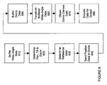
- FIG. 6 a high level flow chart for another process of creating video user interface in accordance with an exemplary implementation of the invention is shown. As with the process illustrated by the flowchart of Figure 5, the steps may be implemented using a system with a programmed processor as described above. Figure 6 may equally represent a high level block diagram of an exemplary system constructed in accordance with the invention, implementing the steps thereof.
- wide-angle data (e.g., fisheye lens image data) is buffered.
- the data may be supplied from a video camera system with a decoder or from a source of pre-recorded data.
- pan, tilt and zoom angles are determined to specify regions of interest in the panoramic views for display in virtual views.
- Pan, tilt and zoom angles may be supplied by a programmed algorithm, a table or a user input module.
- values other than pan, tilt and zoom e.g., Cartesian coordinate values
- reference data for reference windows are determined.
- the reference data preferably corresponds to rectangular windows overlaying the virtual view regions of interest within the panoramic views.
- the rectangular windows move according to a programmed algorithm, a table or user commands from a user input module. As the rectangular windows move, the virtual views correspondingly change.
- step 640 position data is communicated to a dome camera system.
- the communicated position data will cause the dome camera to aim at and zoom to the region of the monitored area corresponding to the determined pan, tilt and zoom values.
- dome camera data is buffered.
- the buffered data may be encoded, without transformation, for output to a display monitor and/or to a recorder as a virtual view.
- step 660 buffered wide-angle data are transformed using a panoramic transformation algorithm for panoramic view data, and using a virtual view transformation algorithm for virtual view data.
- step 670 buffered dome camera data are obtained for encoding.
- the dome camera data may be obtained form a dome camera buffer by a processor and communicated with transformed wide-angle data for encoding.
- the transformed data, dome camera data and reference data are encoded for output.
- the dome camera data defines one virtual view.
- the transformed data defines any other virtual views and the panoramic views.
- the reference data defines the reference windows.
- the encoded output may be sent to a display monitor and/or to a recorder.
- the reference data may be determined before, after or during transformation of the buffered data.
- a pre-programmed pan, tilt and zoom may be determined before the wide-angle data is initially buffered.
- dome position data may be sent before reference data is determined.
- dome data may be buffered after transformation of wide-angle data.
- dome camera data may be obtained by the processor before completion of transformation.
Landscapes
- Engineering & Computer Science (AREA)
- Human Computer Interaction (AREA)
- Physics & Mathematics (AREA)
- General Physics & Mathematics (AREA)
- Multimedia (AREA)
- Signal Processing (AREA)
- General Engineering & Computer Science (AREA)
- Theoretical Computer Science (AREA)
- Studio Devices (AREA)
- Closed-Circuit Television Systems (AREA)
- Image Processing (AREA)
Applications Claiming Priority (2)
| Application Number | Priority Date | Filing Date | Title |
|---|---|---|---|
| US50272803P | 2003-09-12 | 2003-09-12 | |
| US502728P | 2003-09-12 |
Publications (3)
| Publication Number | Publication Date |
|---|---|
| EP1515546A2 true EP1515546A2 (de) | 2005-03-16 |
| EP1515546A3 EP1515546A3 (de) | 2010-01-20 |
| EP1515546B1 EP1515546B1 (de) | 2019-08-07 |
Family
ID=34135389
Family Applications (1)
| Application Number | Title | Priority Date | Filing Date |
|---|---|---|---|
| EP04010139.6A Expired - Lifetime EP1515546B1 (de) | 2003-09-12 | 2004-04-29 | Videobenutzerschnittstellensystem und -verfahren |
Country Status (4)
| Country | Link |
|---|---|
| US (2) | US20050062845A1 (de) |
| EP (1) | EP1515546B1 (de) |
| CA (1) | CA2465045C (de) |
| ES (1) | ES2748129T3 (de) |
Cited By (3)
| Publication number | Priority date | Publication date | Assignee | Title |
|---|---|---|---|---|
| WO2008030135A1 (en) * | 2006-09-04 | 2008-03-13 | Nikolay Ivanovich Palchenko | Method and system for simulating and operating a single virtual space |
| FR2937208A1 (fr) * | 2008-10-13 | 2010-04-16 | Withings | Procede et dispositif de tele-visionnage |
| CN105472344A (zh) * | 2015-12-28 | 2016-04-06 | 北京极图科技有限公司 | 四路拼接式实时全景成像装置 |
Families Citing this family (19)
| Publication number | Priority date | Publication date | Assignee | Title |
|---|---|---|---|---|
| JP2005292879A (ja) * | 2004-03-31 | 2005-10-20 | Fujitsu Ltd | 撮影情報サーバおよび撮影情報送信システム |
| JP2006033257A (ja) * | 2004-07-14 | 2006-02-02 | Fujitsu Ltd | 画像配信装置 |
| US7750936B2 (en) * | 2004-08-06 | 2010-07-06 | Sony Corporation | Immersive surveillance system interface |
| USD619144S1 (en) | 2008-03-04 | 2010-07-06 | Apple Inc. | Icon for a display screen or portion thereof |
| US9792012B2 (en) | 2009-10-01 | 2017-10-17 | Mobile Imaging In Sweden Ab | Method relating to digital images |
| WO2011114610A1 (ja) * | 2010-03-18 | 2011-09-22 | パナソニック株式会社 | 全方位画像処理装置および全方位画像処理方法 |
| CN101827260B (zh) * | 2010-05-06 | 2012-02-01 | 东莞光阵显示器制品有限公司 | 一种视频传输及实时监控的实现方法及系统装置 |
| CN103189796B (zh) | 2010-09-20 | 2015-11-25 | 瑞典移动影像股份公司 | 用于形成图像的方法 |
| US9930225B2 (en) * | 2011-02-10 | 2018-03-27 | Villmer Llc | Omni-directional camera and related viewing software |
| JP2016127377A (ja) * | 2014-12-26 | 2016-07-11 | カシオ計算機株式会社 | 画像処理装置及び画像処理方法、画像再生装置及び画像再生方法、並びにプログラム |
| WO2016187235A1 (en) | 2015-05-20 | 2016-11-24 | Gopro, Inc. | Virtual lens simulation for video and photo cropping |
| WO2017026193A1 (ja) * | 2015-08-12 | 2017-02-16 | ソニー株式会社 | 画像処理装置と画像処理方法とプログラムおよび画像処理システム |
| US10225511B1 (en) | 2015-12-30 | 2019-03-05 | Google Llc | Low power framework for controlling image sensor mode in a mobile image capture device |
| US10732809B2 (en) | 2015-12-30 | 2020-08-04 | Google Llc | Systems and methods for selective retention and editing of images captured by mobile image capture device |
| EP3311750A1 (de) * | 2016-10-18 | 2018-04-25 | Vatech Co. Ltd. | Herstellung einer panoramischen radiografie |
| KR102473815B1 (ko) | 2016-10-18 | 2022-12-05 | 주식회사 바텍 | 엑스선 영상 표시 장치 및 그 방법 |
| USD822711S1 (en) | 2017-06-05 | 2018-07-10 | Apple Inc. | Display screen or portion thereof with graphical user interface |
| CN109151295B (zh) * | 2017-06-16 | 2020-04-03 | 杭州海康威视数字技术股份有限公司 | 一种目标对象抓拍方法、装置及视频监控设备 |
| CN113542848B (zh) * | 2021-06-22 | 2024-04-02 | 惠州市德赛西威汽车电子股份有限公司 | 一种车载影像窗口自定义调节方法及车载系统 |
Citations (2)
| Publication number | Priority date | Publication date | Assignee | Title |
|---|---|---|---|---|
| WO1997050252A1 (en) | 1996-06-24 | 1997-12-31 | Behere Corporation | Panoramic camera |
| WO1999045511A1 (en) | 1998-03-04 | 1999-09-10 | The Trustees Of Columbia University In The City Of New York | A combined wide angle and narrow angle imaging system and method for surveillance and monitoring |
Family Cites Families (20)
| Publication number | Priority date | Publication date | Assignee | Title |
|---|---|---|---|---|
| DE3919265A1 (de) * | 1989-06-13 | 1990-12-20 | Krupp Atlas Elektronik Gmbh | Opto-elektronische ausblickbaugruppe |
| US5185667A (en) * | 1991-05-13 | 1993-02-09 | Telerobotics International, Inc. | Omniview motionless camera orientation system |
| US5359363A (en) * | 1991-05-13 | 1994-10-25 | Telerobotics International, Inc. | Omniview motionless camera surveillance system |
| JPH07504285A (ja) * | 1992-11-24 | 1995-05-11 | フランク・データ・インターナショナル・ナムローゼ・フェンノートシャップ | パノラマ画像の形成方法及び装置並びにパノラマ画像探索方法及び装置 |
| CA2155719C (en) * | 1994-11-22 | 2005-11-01 | Terry Laurence Glatt | Video surveillance system with pilot and slave cameras |
| BR9609867A (pt) * | 1995-07-27 | 1999-04-06 | Sensormatic Electronics Corp | Dispositivo e método de divisão formação e processamento de imagem para uso com câmera sem partes móveis |
| JP4332231B2 (ja) * | 1997-04-21 | 2009-09-16 | ソニー株式会社 | 撮像装置コントローラおよび撮像システム |
| US6624846B1 (en) * | 1997-07-18 | 2003-09-23 | Interval Research Corporation | Visual user interface for use in controlling the interaction of a device with a spatial region |
| US6034716A (en) * | 1997-12-18 | 2000-03-07 | Whiting; Joshua B. | Panoramic digital camera system |
| US7576770B2 (en) * | 2003-02-11 | 2009-08-18 | Raymond Metzger | System for a plurality of video cameras disposed on a common network |
| US7023913B1 (en) * | 2000-06-14 | 2006-04-04 | Monroe David A | Digital security multimedia sensor |
| JP2000152168A (ja) * | 1998-11-13 | 2000-05-30 | Olympus Optical Co Ltd | 画像再生装置 |
| JP3627914B2 (ja) * | 2000-05-23 | 2005-03-09 | シャープ株式会社 | 車両の周囲監視システム |
| JP3773433B2 (ja) * | 2000-10-11 | 2006-05-10 | シャープ株式会社 | 移動体の周囲監視装置 |
| JP3472273B2 (ja) * | 2001-03-07 | 2003-12-02 | キヤノン株式会社 | 画像再生装置及び画像処理装置及び方法 |
| US20020147991A1 (en) * | 2001-04-10 | 2002-10-10 | Furlan John L. W. | Transmission of panoramic video via existing video infrastructure |
| US6833843B2 (en) * | 2001-12-03 | 2004-12-21 | Tempest Microsystems | Panoramic imaging and display system with canonical magnifier |
| JP3925299B2 (ja) * | 2002-05-15 | 2007-06-06 | ソニー株式会社 | モニタリングシステムおよび方法 |
| US6715940B2 (en) * | 2002-09-10 | 2004-04-06 | General Electric Company | Rugged miniature pan/tilt dome camera assembly |
| US7680192B2 (en) * | 2003-07-14 | 2010-03-16 | Arecont Vision, Llc. | Multi-sensor panoramic network camera |
-
2004
- 2004-03-17 US US10/802,451 patent/US20050062845A1/en not_active Abandoned
- 2004-04-22 CA CA2465045A patent/CA2465045C/en not_active Expired - Lifetime
- 2004-04-29 EP EP04010139.6A patent/EP1515546B1/de not_active Expired - Lifetime
- 2004-04-29 ES ES04010139T patent/ES2748129T3/es not_active Expired - Lifetime
-
2013
- 2013-07-19 US US13/946,279 patent/US9955073B2/en not_active Expired - Lifetime
Patent Citations (2)
| Publication number | Priority date | Publication date | Assignee | Title |
|---|---|---|---|---|
| WO1997050252A1 (en) | 1996-06-24 | 1997-12-31 | Behere Corporation | Panoramic camera |
| WO1999045511A1 (en) | 1998-03-04 | 1999-09-10 | The Trustees Of Columbia University In The City Of New York | A combined wide angle and narrow angle imaging system and method for surveillance and monitoring |
Cited By (5)
| Publication number | Priority date | Publication date | Assignee | Title |
|---|---|---|---|---|
| WO2008030135A1 (en) * | 2006-09-04 | 2008-03-13 | Nikolay Ivanovich Palchenko | Method and system for simulating and operating a single virtual space |
| FR2937208A1 (fr) * | 2008-10-13 | 2010-04-16 | Withings | Procede et dispositif de tele-visionnage |
| WO2010043805A1 (fr) * | 2008-10-13 | 2010-04-22 | Withings | Procede et dispositif de tele-visionnage |
| US9019371B2 (en) | 2008-10-13 | 2015-04-28 | Withings | Method and device for tele-viewing |
| CN105472344A (zh) * | 2015-12-28 | 2016-04-06 | 北京极图科技有限公司 | 四路拼接式实时全景成像装置 |
Also Published As
| Publication number | Publication date |
|---|---|
| EP1515546B1 (de) | 2019-08-07 |
| CA2465045C (en) | 2018-05-22 |
| US20130300822A1 (en) | 2013-11-14 |
| EP1515546A3 (de) | 2010-01-20 |
| ES2748129T3 (es) | 2020-03-13 |
| US20050062845A1 (en) | 2005-03-24 |
| CA2465045A1 (en) | 2005-03-12 |
| US9955073B2 (en) | 2018-04-24 |
Similar Documents
| Publication | Publication Date | Title |
|---|---|---|
| US9955073B2 (en) | Video user interface system and method | |
| CA2465087C (en) | Imaging system and method for displaying and/or recording undistorted wide-angle image data | |
| US7161615B2 (en) | System and method for tracking objects and obscuring fields of view under video surveillance | |
| KR101329470B1 (ko) | 화상 처리 장치, 화상 처리 방법 및 그 프로그램을 기록한 기록 매체 | |
| US10091408B2 (en) | Imaging apparatus and method of recognizing target object | |
| JP4268206B2 (ja) | 魚眼レンズカメラ装置及びその画像歪み補正方法 | |
| US8855441B2 (en) | Method and apparatus for transforming a non-linear lens-distorted image | |
| JP5235910B2 (ja) | カメラ雲台システム | |
| JPH11261868A (ja) | 魚眼レンズカメラ装置及びその画像歪み補正方法及び画像抽出方法 | |
| JP2000083242A (ja) | 全視野静止カメラとサ―ベイランスシステム | |
| KR20190075034A (ko) | 차량용 영상 생성 장치 및 방법 | |
| US11190698B2 (en) | Imaging apparatus, control method for imaging apparatus, information processing apparatus, and storage medium | |
| KR101778744B1 (ko) | 다중 카메라 입력의 합성을 통한 실시간 모니터링 시스템 | |
| JP2006245793A (ja) | 撮像システム | |
| JP3594225B2 (ja) | 広視野カメラ装置 | |
| US6876387B1 (en) | Digital zoom-out processing apparatus | |
| US8860780B1 (en) | Automatic pivoting in a wide-angle video camera | |
| HK1078212A (en) | Video user interface system and method | |
| HK1078213A (en) | Imaging system and method for displaying and/or recording undistorted wide-angle image data | |
| HK1078213B (en) | Imaging system and method for displaying and/or recording undistorted wide-angle image data | |
| EP4009622B1 (de) | Verfahren zur erfassung und verarbeitung eines digitalen panoramabildes | |
| WO1996008105A1 (en) | Method for creating image data | |
| KR20180022327A (ko) | Cctv 카메라의 360도 영상 변환 장치 | |
| JP2019009574A (ja) | 画像処理装置 | |
| KR20250102434A (ko) | 팬틸트줌 카메라 운용 시스템 |
Legal Events
| Date | Code | Title | Description |
|---|---|---|---|
| PUAI | Public reference made under article 153(3) epc to a published international application that has entered the european phase |
Free format text: ORIGINAL CODE: 0009012 |
|
| AK | Designated contracting states |
Kind code of ref document: A2 Designated state(s): AT BE BG CH CY CZ DE DK EE ES FI FR GB GR HU IE IT LI LU MC NL PL PT RO SE SI SK TR |
|
| AX | Request for extension of the european patent |
Extension state: AL HR LT LV MK |
|
| REG | Reference to a national code |
Ref country code: HK Ref legal event code: DE Ref document number: 1078212 Country of ref document: HK |
|
| PUAL | Search report despatched |
Free format text: ORIGINAL CODE: 0009013 |
|
| AK | Designated contracting states |
Kind code of ref document: A3 Designated state(s): AT BE BG CH CY CZ DE DK EE ES FI FR GB GR HU IE IT LI LU MC NL PL PT RO SE SI SK TR |
|
| AX | Request for extension of the european patent |
Extension state: AL HR LT LV MK |
|
| 17P | Request for examination filed |
Effective date: 20100715 |
|
| AKX | Designation fees paid |
Designated state(s): AT BE BG CH CY CZ DE DK EE ES FI FR GB GR HU IE IT LI LU MC NL PL PT RO SE SI SK TR |
|
| 17Q | First examination report despatched |
Effective date: 20100917 |
|
| RAP1 | Party data changed (applicant data changed or rights of an application transferred) |
Owner name: SENSORMATIC ELECTRONICS, LLC |
|
| RAP1 | Party data changed (applicant data changed or rights of an application transferred) |
Owner name: TYCO FIRE & SECURITY GMBH |
|
| RAP1 | Party data changed (applicant data changed or rights of an application transferred) |
Owner name: SENSORMATIC ELECTRONICS, LLC |
|
| GRAP | Despatch of communication of intention to grant a patent |
Free format text: ORIGINAL CODE: EPIDOSNIGR1 |
|
| STAA | Information on the status of an ep patent application or granted ep patent |
Free format text: STATUS: GRANT OF PATENT IS INTENDED |
|
| INTG | Intention to grant announced |
Effective date: 20190225 |
|
| GRAS | Grant fee paid |
Free format text: ORIGINAL CODE: EPIDOSNIGR3 |
|
| GRAA | (expected) grant |
Free format text: ORIGINAL CODE: 0009210 |
|
| STAA | Information on the status of an ep patent application or granted ep patent |
Free format text: STATUS: THE PATENT HAS BEEN GRANTED |
|
| AK | Designated contracting states |
Kind code of ref document: B1 Designated state(s): AT BE BG CH CY CZ DE DK EE ES FI FR GB GR HU IE IT LI LU MC NL PL PT RO SE SI SK TR |
|
| REG | Reference to a national code |
Ref country code: GB Ref legal event code: FG4D |
|
| REG | Reference to a national code |
Ref country code: CH Ref legal event code: EP Ref country code: AT Ref legal event code: REF Ref document number: 1165650 Country of ref document: AT Kind code of ref document: T Effective date: 20190815 |
|
| REG | Reference to a national code |
Ref country code: DE Ref legal event code: R096 Ref document number: 602004054169 Country of ref document: DE |
|
| REG | Reference to a national code |
Ref country code: IE Ref legal event code: FG4D |
|
| REG | Reference to a national code |
Ref country code: NL Ref legal event code: MP Effective date: 20190807 |
|
| PG25 | Lapsed in a contracting state [announced via postgrant information from national office to epo] |
Ref country code: NL Free format text: LAPSE BECAUSE OF FAILURE TO SUBMIT A TRANSLATION OF THE DESCRIPTION OR TO PAY THE FEE WITHIN THE PRESCRIBED TIME-LIMIT Effective date: 20190807 Ref country code: SE Free format text: LAPSE BECAUSE OF FAILURE TO SUBMIT A TRANSLATION OF THE DESCRIPTION OR TO PAY THE FEE WITHIN THE PRESCRIBED TIME-LIMIT Effective date: 20190807 Ref country code: BG Free format text: LAPSE BECAUSE OF FAILURE TO SUBMIT A TRANSLATION OF THE DESCRIPTION OR TO PAY THE FEE WITHIN THE PRESCRIBED TIME-LIMIT Effective date: 20191107 Ref country code: FI Free format text: LAPSE BECAUSE OF FAILURE TO SUBMIT A TRANSLATION OF THE DESCRIPTION OR TO PAY THE FEE WITHIN THE PRESCRIBED TIME-LIMIT Effective date: 20190807 Ref country code: PT Free format text: LAPSE BECAUSE OF FAILURE TO SUBMIT A TRANSLATION OF THE DESCRIPTION OR TO PAY THE FEE WITHIN THE PRESCRIBED TIME-LIMIT Effective date: 20191209 |
|
| REG | Reference to a national code |
Ref country code: AT Ref legal event code: MK05 Ref document number: 1165650 Country of ref document: AT Kind code of ref document: T Effective date: 20190807 |
|
| PG25 | Lapsed in a contracting state [announced via postgrant information from national office to epo] |
Ref country code: GR Free format text: LAPSE BECAUSE OF FAILURE TO SUBMIT A TRANSLATION OF THE DESCRIPTION OR TO PAY THE FEE WITHIN THE PRESCRIBED TIME-LIMIT Effective date: 20191108 |
|
| REG | Reference to a national code |
Ref country code: ES Ref legal event code: FG2A Ref document number: 2748129 Country of ref document: ES Kind code of ref document: T3 Effective date: 20200313 |
|
| PG25 | Lapsed in a contracting state [announced via postgrant information from national office to epo] |
Ref country code: TR Free format text: LAPSE BECAUSE OF FAILURE TO SUBMIT A TRANSLATION OF THE DESCRIPTION OR TO PAY THE FEE WITHIN THE PRESCRIBED TIME-LIMIT Effective date: 20190807 |
|
| PG25 | Lapsed in a contracting state [announced via postgrant information from national office to epo] |
Ref country code: AT Free format text: LAPSE BECAUSE OF FAILURE TO SUBMIT A TRANSLATION OF THE DESCRIPTION OR TO PAY THE FEE WITHIN THE PRESCRIBED TIME-LIMIT Effective date: 20190807 Ref country code: DK Free format text: LAPSE BECAUSE OF FAILURE TO SUBMIT A TRANSLATION OF THE DESCRIPTION OR TO PAY THE FEE WITHIN THE PRESCRIBED TIME-LIMIT Effective date: 20190807 Ref country code: PL Free format text: LAPSE BECAUSE OF FAILURE TO SUBMIT A TRANSLATION OF THE DESCRIPTION OR TO PAY THE FEE WITHIN THE PRESCRIBED TIME-LIMIT Effective date: 20190807 Ref country code: RO Free format text: LAPSE BECAUSE OF FAILURE TO SUBMIT A TRANSLATION OF THE DESCRIPTION OR TO PAY THE FEE WITHIN THE PRESCRIBED TIME-LIMIT Effective date: 20190807 Ref country code: IT Free format text: LAPSE BECAUSE OF FAILURE TO SUBMIT A TRANSLATION OF THE DESCRIPTION OR TO PAY THE FEE WITHIN THE PRESCRIBED TIME-LIMIT Effective date: 20190807 Ref country code: EE Free format text: LAPSE BECAUSE OF FAILURE TO SUBMIT A TRANSLATION OF THE DESCRIPTION OR TO PAY THE FEE WITHIN THE PRESCRIBED TIME-LIMIT Effective date: 20190807 |
|
| PG25 | Lapsed in a contracting state [announced via postgrant information from national office to epo] |
Ref country code: CZ Free format text: LAPSE BECAUSE OF FAILURE TO SUBMIT A TRANSLATION OF THE DESCRIPTION OR TO PAY THE FEE WITHIN THE PRESCRIBED TIME-LIMIT Effective date: 20190807 Ref country code: SK Free format text: LAPSE BECAUSE OF FAILURE TO SUBMIT A TRANSLATION OF THE DESCRIPTION OR TO PAY THE FEE WITHIN THE PRESCRIBED TIME-LIMIT Effective date: 20190807 |
|
| REG | Reference to a national code |
Ref country code: DE Ref legal event code: R097 Ref document number: 602004054169 Country of ref document: DE |
|
| PLBE | No opposition filed within time limit |
Free format text: ORIGINAL CODE: 0009261 |
|
| STAA | Information on the status of an ep patent application or granted ep patent |
Free format text: STATUS: NO OPPOSITION FILED WITHIN TIME LIMIT |
|
| 26N | No opposition filed |
Effective date: 20200603 |
|
| PG25 | Lapsed in a contracting state [announced via postgrant information from national office to epo] |
Ref country code: SI Free format text: LAPSE BECAUSE OF FAILURE TO SUBMIT A TRANSLATION OF THE DESCRIPTION OR TO PAY THE FEE WITHIN THE PRESCRIBED TIME-LIMIT Effective date: 20190807 |
|
| PG25 | Lapsed in a contracting state [announced via postgrant information from national office to epo] |
Ref country code: MC Free format text: LAPSE BECAUSE OF FAILURE TO SUBMIT A TRANSLATION OF THE DESCRIPTION OR TO PAY THE FEE WITHIN THE PRESCRIBED TIME-LIMIT Effective date: 20190807 |
|
| REG | Reference to a national code |
Ref country code: CH Ref legal event code: PL |
|
| PG25 | Lapsed in a contracting state [announced via postgrant information from national office to epo] |
Ref country code: LU Free format text: LAPSE BECAUSE OF NON-PAYMENT OF DUE FEES Effective date: 20200429 Ref country code: LI Free format text: LAPSE BECAUSE OF NON-PAYMENT OF DUE FEES Effective date: 20200430 Ref country code: CH Free format text: LAPSE BECAUSE OF NON-PAYMENT OF DUE FEES Effective date: 20200430 |
|
| REG | Reference to a national code |
Ref country code: BE Ref legal event code: MM Effective date: 20200430 |
|
| PG25 | Lapsed in a contracting state [announced via postgrant information from national office to epo] |
Ref country code: BE Free format text: LAPSE BECAUSE OF NON-PAYMENT OF DUE FEES Effective date: 20200430 |
|
| PG25 | Lapsed in a contracting state [announced via postgrant information from national office to epo] |
Ref country code: IE Free format text: LAPSE BECAUSE OF NON-PAYMENT OF DUE FEES Effective date: 20200429 |
|
| PG25 | Lapsed in a contracting state [announced via postgrant information from national office to epo] |
Ref country code: CY Free format text: LAPSE BECAUSE OF FAILURE TO SUBMIT A TRANSLATION OF THE DESCRIPTION OR TO PAY THE FEE WITHIN THE PRESCRIBED TIME-LIMIT Effective date: 20190807 |
|
| REG | Reference to a national code |
Ref country code: DE Ref legal event code: R079 Ref document number: 602004054169 Country of ref document: DE Free format text: PREVIOUS MAIN CLASS: H04N0005232000 Ipc: H04N0023600000 |
|
| PGFP | Annual fee paid to national office [announced via postgrant information from national office to epo] |
Ref country code: FR Payment date: 20230421 Year of fee payment: 20 Ref country code: ES Payment date: 20230515 Year of fee payment: 20 Ref country code: DE Payment date: 20230427 Year of fee payment: 20 |
|
| PGFP | Annual fee paid to national office [announced via postgrant information from national office to epo] |
Ref country code: GB Payment date: 20230418 Year of fee payment: 20 |
|
| REG | Reference to a national code |
Ref country code: DE Ref legal event code: R071 Ref document number: 602004054169 Country of ref document: DE |
|
| REG | Reference to a national code |
Ref country code: ES Ref legal event code: FD2A Effective date: 20240508 |
|
| REG | Reference to a national code |
Ref country code: GB Ref legal event code: PE20 Expiry date: 20240428 |
|
| PG25 | Lapsed in a contracting state [announced via postgrant information from national office to epo] |
Ref country code: GB Free format text: LAPSE BECAUSE OF EXPIRATION OF PROTECTION Effective date: 20240428 |
|
| PG25 | Lapsed in a contracting state [announced via postgrant information from national office to epo] |
Ref country code: ES Free format text: LAPSE BECAUSE OF EXPIRATION OF PROTECTION Effective date: 20240430 |
|
| PG25 | Lapsed in a contracting state [announced via postgrant information from national office to epo] |
Ref country code: GB Free format text: LAPSE BECAUSE OF EXPIRATION OF PROTECTION Effective date: 20240428 Ref country code: ES Free format text: LAPSE BECAUSE OF EXPIRATION OF PROTECTION Effective date: 20240430 |
|
| REG | Reference to a national code |
Ref country code: HK Ref legal event code: WD Ref document number: 1078212 Country of ref document: HK |