EP1515413A1 - Halterstruktur für Hochspannungsleiter - Google Patents
Halterstruktur für Hochspannungsleiter Download PDFInfo
- Publication number
- EP1515413A1 EP1515413A1 EP04077448A EP04077448A EP1515413A1 EP 1515413 A1 EP1515413 A1 EP 1515413A1 EP 04077448 A EP04077448 A EP 04077448A EP 04077448 A EP04077448 A EP 04077448A EP 1515413 A1 EP1515413 A1 EP 1515413A1
- Authority
- EP
- European Patent Office
- Prior art keywords
- spacer block
- voltage conductor
- voltage
- substantially planar
- width
- Prior art date
- Legal status (The legal status is an assumption and is not a legal conclusion. Google has not performed a legal analysis and makes no representation as to the accuracy of the status listed.)
- Granted
Links
- 239000004020 conductor Substances 0.000 title claims abstract description 80
- 125000006850 spacer group Chemical group 0.000 claims abstract description 76
- 238000000034 method Methods 0.000 claims description 10
- 239000012772 electrical insulation material Substances 0.000 claims description 4
- 239000011810 insulating material Substances 0.000 claims description 4
- SGPGESCZOCHFCL-UHFFFAOYSA-N Tilisolol hydrochloride Chemical compound [Cl-].C1=CC=C2C(=O)N(C)C=C(OCC(O)C[NH2+]C(C)(C)C)C2=C1 SGPGESCZOCHFCL-UHFFFAOYSA-N 0.000 claims 1
- 238000004804 winding Methods 0.000 description 13
- 239000007789 gas Substances 0.000 description 10
- 238000012360 testing method Methods 0.000 description 5
- 239000001257 hydrogen Substances 0.000 description 3
- 229910052739 hydrogen Inorganic materials 0.000 description 3
- 238000005259 measurement Methods 0.000 description 3
- 238000000926 separation method Methods 0.000 description 3
- 239000004593 Epoxy Substances 0.000 description 2
- UFHFLCQGNIYNRP-UHFFFAOYSA-N Hydrogen Chemical compound [H][H] UFHFLCQGNIYNRP-UHFFFAOYSA-N 0.000 description 2
- 230000015556 catabolic process Effects 0.000 description 2
- 239000003822 epoxy resin Substances 0.000 description 2
- 238000009413 insulation Methods 0.000 description 2
- 239000002648 laminated material Substances 0.000 description 2
- 229920000647 polyepoxide Polymers 0.000 description 2
- RYGMFSIKBFXOCR-UHFFFAOYSA-N Copper Chemical compound [Cu] RYGMFSIKBFXOCR-UHFFFAOYSA-N 0.000 description 1
- 238000013459 approach Methods 0.000 description 1
- 229910052802 copper Inorganic materials 0.000 description 1
- 239000010949 copper Substances 0.000 description 1
- 239000011521 glass Substances 0.000 description 1
- 150000002431 hydrogen Chemical class 0.000 description 1
- 239000000463 material Substances 0.000 description 1
- 238000012986 modification Methods 0.000 description 1
- 230000004048 modification Effects 0.000 description 1
- 238000012546 transfer Methods 0.000 description 1
Images


Classifications
-
- H—ELECTRICITY
- H02—GENERATION; CONVERSION OR DISTRIBUTION OF ELECTRIC POWER
- H02K—DYNAMO-ELECTRIC MACHINES
- H02K3/00—Details of windings
- H02K3/46—Fastening of windings on the stator or rotor structure
- H02K3/50—Fastening of winding heads, equalising connectors, or connections thereto
- H02K3/505—Fastening of winding heads, equalising connectors, or connections thereto for large machine windings, e.g. bar windings
Definitions
- the present invention relates generally to support structures for use in electric machines, and more particularly to support structures configured to reduce electrical creep between high-voltage conductors.
- Industrial turbine generators may operate at voltages as high as 30,000 volts and currents as high as 15,000 amps.
- industrial electric machines utilize large, specially-configured conductors known as high-voltage conductors.
- Stator windings are located in the stator core of a generator. Stator windings conduct the alternating current and voltage induced by a generator's field windings.
- Parallel rings are located near the ends of a generator. Parallel rings provide an electrical path from the stator windings of a generator to the main leads. Parallel rings conduct the same high-level alternating currents and voltages that are conducted by stator windings.
- High-voltage conductors like stator windings and parallel rings, are mechanically supported within an electric machine by specially-configured support structures.
- the support structures often include rectangular spacer blocks for mechanically separating adjacent high-voltage conductors. These rectangular spacer blocks are generally positioned periodically between adjacent high-voltage conductors in order to maintain a fixed distance between them. This improves the mechanical performance of an electric machine by providing rigid support for and separation of high-voltage conductors.
- conventional-rectangular spacer blocks also impair the electrical performance of an electric machine by increasing the chance of creep between the high-voltage conductors.
- high-voltage conductors When high-voltage conductors are separated by a conventional-rectangular spacer block, they become susceptible to electrical flashover in the form of creep. To address this problem, high-voltage conductors can be further insulated or spaced farther apart. But, adding additional insulation to high-voltage conductor reduces their ability to dissipate heat. Moreover, spacing the conductors further apart causes an undesirable increase in the size of the electric machine.
- An exemplary support structure includes an improved spacer block that is configured to reduce creep between adjacent conductors, without necessarily increasing the width of the spacer block or the overall size of the electric machine.
- a spacer block that includes a main body constructed of an insulating material.
- the main body has a principal width W for separating a first and second high-voltage electrical conductor by a distance substantially equal to the principle width W.
- the spacer block has an exposed surface along the principal width, extending from the first high-voltage conductor to the second high-voltage conductor.
- the spacer block includes a protruding portion that protrudes from the main body and elongates the exposed surface to form an elongated creepage path between the first and second high-voltage electrical conductor. The creepage path is greater in length than the principal width W of the spacer block.
- a support structure that comprises a brace constructed of an electrical-insulation material and configured to be rigidly mounted to an electric machine to mechanically support a first and second high-voltage conductor.
- the brace has a support surface on which the first and second high-voltage conductor are positioned.
- the support structure also includes a spacer block that has a principal width W and is constructed of an electrical-insulation material. The spacer block is configured to be mounted between the first and second high-voltage conductors to space the first and second high-voltage conductor apart by a distance of substantially W.
- the spacer block includes a protruding portion that comprises a substantially rectangular protrusion that protrudes from the spacer block to form an elongated surface over the spacer block between the first and second high-voltage conductor.
- a creepage path is formed over the substantially shortest path over the elongated surface from the first high-voltage conductor to the second high-voltage conductor.
- the creepage path has a length L that is greater than the principal width W of the spacer block 13.
- a method of mechanically supporting and spacing apart a first and second high-voltage conductor comprises the steps of positioning an insulating spacer block between the first and second high-voltage conductor to space apart the first and second high-voltage conductor by a distance W substantially equal to a principal width of the spacer block.
- the spacer block comprises a main body having a substantially rectangular main body and at least one protruding portion for increasing a creepage path between the first and second high-voltage conductor to a length L that is greater than the principal width W of the spacer block.
- Strike is an electrical discharge through an open-gas gap between conductors.
- Creep is an electrical discharge over an insulated surface, such as a spacer block between conductors.
- Conventional rectangular-spacer blocks tend to reduce the electrical performance of an electric machine by introducing a creepage path between adjacent conductors. In other words, if a first pair of conductors is separated by an open gas gap of width W and a second pair of conductors is separated by a conventional-rectangular spacer block of width W, electrical flashover will occur at a lower voltage for the conductors separated by the spacer block.
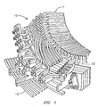
- FIG. 1 illustrates an end region 10 of a large turbine generator, which is one example of a context in which methods and apparatuses consistent with the present invention may be utilized.
- the end region 10 includes various high-voltage conductors for conducting electrical energy.
- the high-voltage conductors illustrated include stator windings 11 and parallel rings 12.
- the stator windings 11 are disposed within a generally cylindrical stator core.
- the stator windings generally also include (not illustrated) a plurality of phase zones each of which constitute a plurality of coil sides.
- the coil sides in each phase, except those constituting the terminal coil side portions, are serially connected at each axial end of the stator core.
- the unconnected ends of the terminal coil sides constitute terminals, which are radially separated from the axis of the stator core by discrete radial distances at a first axial end of the stator core.
- stator windings 11 are electrically connected to high-voltage conductors referred to as parallel rings 12.
- the parallel rings 12 comprise large copper bus bars that encircle the end of the generator.
- stator windings 11 and parallel rings 12 are the phase-to-phase voltage of the generator, which may be as high as 30,000 volts.
- stator windings 11 and parallel rings 12 may be susceptible to electrical flashover in the form of strike or creep.
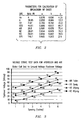
- V the strike voltage in kilovolts rms (kVrms)
- P the gas pressure in atmospheres (atm)
- T the absolute temperature in K
- R the gas constant 0.08205 liters atm/mole K
- d the gap width in millimeters
- a, b and c are gas constants.
- Figure 2 illustrates gas constants for use in this formula for calculating electrical strike in several exemplary gases. Hydrogen (H 2 ) and air are particularly common gases in electric machinery because of their desirable heat-transfer characteristics.
- Figure 3 illustrates actual test data obtained for strike in hydrogen and air at various gap sizes.
- conventional-rectangular spacer blocks used to mechanically separate high-voltage conductors actually reduce the flashover voltage for a given conductor separation.
- conventional-rectangular-spacer blocks may reduce the flashover voltage for a given conductor separation by as much as 80%.
- a conventional approach to this problem is to increase the width of the spacer block. However, this adds significant, unwanted size to the associated electric machine.
- Figures 4 and 5A-D illustrate an improved-spacer block consistent with the present invention for increasing the flashover voltage between high-voltage conductors without necessarily increasing the width of the spacer block.
- Figure 4 illustrates an exemplary support structure 20 consistent with the present invention for supporting high-voltage conductors, such as those illustrated in Figure 1.
- the support structure 20 includes a brace 21.
- the brace 21 may be constructed of any rigid insulating material. Examples of such materials include green-glass-epoxy resin or a glass-epoxy rigid laminate material.
- the support structure 20 is configured to be fixedly attached to an electric machine, such as an electrical generator.
- One or more high-voltage conductors 12 may rest on or may be fixedly attached to the brace 21.
- the support structure 20 is configured for use with one or more improved spacer blocks 22.
- Figures 5A-D illustrate an exemplary embodiment of an improved spacer block consistent with the present invention.
- the improved spacer block may be constructed of a rigid insulating material, such as green-glass-epoxy resin or a glass-epoxy rigid laminate material.
- the improved spacer block 22 is configured to be positioned between adjacent high-voltage conductors.
- the improved spacer block 22 has a principal width W for separating the adjacent conductors by a distance substantially equal to W.
- the improved spacer block 22 has a creepage path 30 of length L, which is defined by the path from one conductor to an adjacent conductor over the surface of the improved spacer block 22.
- the length L of the creepage path 30 is greater than the width W of the improved spacer block.
- the increase in the length L of the creepage path 30 may be achieved, for example, by forming the improved-spacer block 22 to have a profile with a varying height.
- the exemplary profile illustrated in Figures 5A-D has a protruding portion 32 comprising a rectangular step up region formed at the center of the block, with a height H above the main body 33 and a width smaller than the width W of the main body 33. This exemplary profile results in a creepage path having a length L that is equal to W + 2H.
- the protruding portion may protrude from only three sides of the spacer block's main body as illustrated in Figure 5A or may protrude from all four sides of the main body if accommodating modifications are made to the brace 21.
- the creepage flashover voltage level is raised by approximatelyl 17%.
- edges and corners of the main body 33 and protruding portion 32 may also be smoothed to increase the corona inception voltage at the edges and corners of the spacer block.
- Tests were conducted on the exemplary embodiment illustrated in Figures 4 and 5A-D. The tests compared the flashover voltage between two flat, insulated conductors when the conductors were separated by (i) an air gap, (ii) a conventional rectangular spacer block and (iii) the improved spacer block.
- the conductors were hand taped with a nominal single-wall insulation thickness of 0.11 inches. Flashover measurements were first made with the conductors separated by a 2 inch air gap. In that configuration, flashover occurred between 60 kVrms and 65 kVrms in the form of strike. Next, flashover measurements were made with the conductors separated by a conventional-rectangular spacer block constructed of G11 green glass having a width and creepage-path length of 2 inches.
- flashover occurred at 52 kVrms in the form of creep. Flashover measurements were then made with the conductors separated by the improved spacer block illustrated in Figures 5A-5D with a width of 2 inches, a height of 3.5 inches and a creepage-path length of 9 inches. In that configuration, flashover occurred at 60 kVrms in the form of creep.
- the exemplary embodiment of the improved-spacer block provided an effective increase in creep voltage on the order of 17 percent.
Landscapes
- Engineering & Computer Science (AREA)
- Power Engineering (AREA)
- Insulation, Fastening Of Motor, Generator Windings (AREA)
Applications Claiming Priority (2)
| Application Number | Priority Date | Filing Date | Title |
|---|---|---|---|
| US661687 | 1996-06-11 | ||
| US10/661,687 US7002278B2 (en) | 2003-09-12 | 2003-09-12 | Support structure for high-voltage conductors |
Publications (2)
| Publication Number | Publication Date |
|---|---|
| EP1515413A1 true EP1515413A1 (de) | 2005-03-16 |
| EP1515413B1 EP1515413B1 (de) | 2007-05-02 |
Family
ID=34136795
Family Applications (1)
| Application Number | Title | Priority Date | Filing Date |
|---|---|---|---|
| EP04077448A Expired - Lifetime EP1515413B1 (de) | 2003-09-12 | 2004-09-02 | Halterstruktur für Hochspannungsleiter |
Country Status (3)
| Country | Link |
|---|---|
| US (1) | US7002278B2 (de) |
| EP (1) | EP1515413B1 (de) |
| DE (1) | DE602004006207T2 (de) |
Families Citing this family (6)
| Publication number | Priority date | Publication date | Assignee | Title |
|---|---|---|---|---|
| US7604399B2 (en) * | 2007-05-31 | 2009-10-20 | Siemens Energy, Inc. | Temperature monitor for bus structure flex connector |
| US8978239B2 (en) | 2013-01-09 | 2015-03-17 | General Electric Company | Field coil winding assembly |
| DE102021105651A1 (de) | 2021-03-09 | 2022-09-15 | Dr. Ing. H.C. F. Porsche Aktiengesellschaft | Hochvolt-Elektromotor-Statoranordnung |
| US11962205B2 (en) * | 2021-03-16 | 2024-04-16 | The Timken Company | Mechanical strength of connection of wound rotor generator/motor |
| AT524971A1 (de) * | 2021-04-27 | 2022-11-15 | Andritz Hydro Gmbh | Rotor für eine elektrische Maschine |
| DE102023111179A1 (de) * | 2023-05-02 | 2024-11-07 | Schaeffler Technologies AG & Co. KG | Hochvolt-Terminal für einen Stator, Stator und Verfahren zur Herstellung eines Hochvolt-Terminals |
Citations (5)
| Publication number | Priority date | Publication date | Assignee | Title |
|---|---|---|---|---|
| US2677067A (en) * | 1952-07-02 | 1954-04-27 | Westinghouse Electric Corp | Spacer for bracing end windings of electrical machines |
| GB956724A (en) * | 1959-11-20 | 1964-04-29 | Gen Electric | Improvements in spacing means for conductor bars of electrical devices |
| US5373211A (en) * | 1994-02-14 | 1994-12-13 | Westinghouse Electric Corporation | Turbine generator stator end floating winding support |
| WO1998020598A1 (en) * | 1996-11-04 | 1998-05-14 | Asea Brown Boveri Ab | Device for controlling fault currents in a rotating electric machine |
| JP2003134753A (ja) * | 2001-10-26 | 2003-05-09 | Sumitomo Wiring Syst Ltd | 車両用薄型ブラシレスモータの集中配電部材の製造方法 |
Family Cites Families (2)
| Publication number | Priority date | Publication date | Assignee | Title |
|---|---|---|---|---|
| US2980757A (en) * | 1959-11-20 | 1961-04-18 | Gen Electric | Spacing means for electrical devices |
| JP3733316B2 (ja) * | 2001-10-26 | 2006-01-11 | 住友電装株式会社 | 車両用薄型ブラシレスモータの集中配電部材 |
-
2003
- 2003-09-12 US US10/661,687 patent/US7002278B2/en not_active Expired - Lifetime
-
2004
- 2004-09-02 EP EP04077448A patent/EP1515413B1/de not_active Expired - Lifetime
- 2004-09-02 DE DE602004006207T patent/DE602004006207T2/de not_active Expired - Lifetime
Patent Citations (6)
| Publication number | Priority date | Publication date | Assignee | Title |
|---|---|---|---|---|
| US2677067A (en) * | 1952-07-02 | 1954-04-27 | Westinghouse Electric Corp | Spacer for bracing end windings of electrical machines |
| GB956724A (en) * | 1959-11-20 | 1964-04-29 | Gen Electric | Improvements in spacing means for conductor bars of electrical devices |
| US5373211A (en) * | 1994-02-14 | 1994-12-13 | Westinghouse Electric Corporation | Turbine generator stator end floating winding support |
| WO1998020598A1 (en) * | 1996-11-04 | 1998-05-14 | Asea Brown Boveri Ab | Device for controlling fault currents in a rotating electric machine |
| JP2003134753A (ja) * | 2001-10-26 | 2003-05-09 | Sumitomo Wiring Syst Ltd | 車両用薄型ブラシレスモータの集中配電部材の製造方法 |
| US20030173841A1 (en) * | 2001-10-26 | 2003-09-18 | Sumitomo Wiring Systems, Ltd. | Method for producing centralized distribution unit of thin brushless motor for vehicle |
Non-Patent Citations (1)
| Title |
|---|
| PATENT ABSTRACTS OF JAPAN vol. 2003, no. 09 3 September 2003 (2003-09-03) * |
Also Published As
| Publication number | Publication date |
|---|---|
| EP1515413B1 (de) | 2007-05-02 |
| US20050057115A1 (en) | 2005-03-17 |
| DE602004006207T2 (de) | 2007-12-27 |
| DE602004006207D1 (de) | 2007-06-14 |
| US7002278B2 (en) | 2006-02-21 |
Similar Documents
| Publication | Publication Date | Title |
|---|---|---|
| CN101546932B (zh) | 具有磁路的高压旋转电机及其制造方法 | |
| AU2007240248B2 (en) | Non-linear dielectrics used as electrical insulation | |
| KR100447489B1 (ko) | 고전압권선용절연전도체 | |
| KR102046187B1 (ko) | 연속 전치 전도체 | |
| US11114232B2 (en) | Inductor assemblies | |
| JP2000511337A (ja) | 高圧巻線用絶縁導体およびその製造方法 | |
| EP1034607B1 (de) | Isolierter leiter für hochspannungsmaschinewicklungen | |
| US7002278B2 (en) | Support structure for high-voltage conductors | |
| JP2001503597A (ja) | 回転電気機械における故障電流制御装置 | |
| US1891716A (en) | Winding for dynamo electric machines | |
| NO326865B1 (no) | Induksjonsvikling | |
| Philippe et al. | Tool to design the primary electrical insulation system of low voltage rotating machines fed by inverters | |
| CN201918720U (zh) | 消除电弧闪络的中性点接地电阻 | |
| US1039298A (en) | Step-by-step insulation for electric conductors or the like. | |
| Touma-Holmberg et al. | Suppression of slot discharges in a cable wound generator | |
| US9543800B2 (en) | External corona shielding for an electrical machine | |
| JP2924274B2 (ja) | 円板巻線の製造方法 | |
| KR102882973B1 (ko) | 변압기 | |
| Mavroidis et al. | Impulse breakdown of short rod-plane air gaps with a dielectric covered rod | |
| KR860001587Y1 (ko) | 카본 브러쉬 | |
| JPH04123411A (ja) | 変圧器巻線 | |
| JP2000260636A (ja) | 静止誘導機器 | |
| Ishikawa et al. | Partial Discharge Characteristics of Small Gas Gaps in SF6 Gas | |
| JPS6222351B2 (de) | ||
| JP2002118021A (ja) | 静止形誘導機器 |
Legal Events
| Date | Code | Title | Description |
|---|---|---|---|
| PUAI | Public reference made under article 153(3) epc to a published international application that has entered the european phase |
Free format text: ORIGINAL CODE: 0009012 |
|
| AK | Designated contracting states |
Kind code of ref document: A1 Designated state(s): AT BE BG CH CY CZ DE DK EE ES FI FR GB GR HU IE IT LI LU MC NL PL PT RO SE SI SK TR |
|
| AX | Request for extension of the european patent |
Extension state: AL HR LT LV MK |
|
| 17P | Request for examination filed |
Effective date: 20050802 |
|
| AKX | Designation fees paid |
Designated state(s): DE FR GB IT |
|
| RAP1 | Party data changed (applicant data changed or rights of an application transferred) |
Owner name: SIEMENS POWER GENERATION, INC. |
|
| GRAP | Despatch of communication of intention to grant a patent |
Free format text: ORIGINAL CODE: EPIDOSNIGR1 |
|
| GRAS | Grant fee paid |
Free format text: ORIGINAL CODE: EPIDOSNIGR3 |
|
| GRAA | (expected) grant |
Free format text: ORIGINAL CODE: 0009210 |
|
| AK | Designated contracting states |
Kind code of ref document: B1 Designated state(s): DE FR GB IT |
|
| REG | Reference to a national code |
Ref country code: GB Ref legal event code: FG4D |
|
| REF | Corresponds to: |
Ref document number: 602004006207 Country of ref document: DE Date of ref document: 20070614 Kind code of ref document: P |
|
| ET | Fr: translation filed | ||
| PLBE | No opposition filed within time limit |
Free format text: ORIGINAL CODE: 0009261 |
|
| STAA | Information on the status of an ep patent application or granted ep patent |
Free format text: STATUS: NO OPPOSITION FILED WITHIN TIME LIMIT |
|
| 26N | No opposition filed |
Effective date: 20080205 |
|
| REG | Reference to a national code |
Ref country code: DE Ref legal event code: R081 Ref document number: 602004006207 Country of ref document: DE Owner name: SIEMENS ENERGY, INC.(N.D. GES.D. STAATES DELAW, US Free format text: FORMER OWNER: SIEMENS POWER GENERATION, INC., ORLANDO, FLA., US Effective date: 20110516 |
|
| REG | Reference to a national code |
Ref country code: FR Ref legal event code: CD Owner name: SIEMENS ENERGY, INC. Effective date: 20120413 |
|
| REG | Reference to a national code |
Ref country code: FR Ref legal event code: PLFP Year of fee payment: 13 |
|
| REG | Reference to a national code |
Ref country code: FR Ref legal event code: PLFP Year of fee payment: 14 |
|
| PGFP | Annual fee paid to national office [announced via postgrant information from national office to epo] |
Ref country code: IT Payment date: 20170629 Year of fee payment: 14 |
|
| REG | Reference to a national code |
Ref country code: FR Ref legal event code: PLFP Year of fee payment: 15 |
|
| PGFP | Annual fee paid to national office [announced via postgrant information from national office to epo] |
Ref country code: FR Payment date: 20180924 Year of fee payment: 15 |
|
| PGFP | Annual fee paid to national office [announced via postgrant information from national office to epo] |
Ref country code: GB Payment date: 20180911 Year of fee payment: 15 |
|
| PGFP | Annual fee paid to national office [announced via postgrant information from national office to epo] |
Ref country code: DE Payment date: 20181119 Year of fee payment: 15 |
|
| PG25 | Lapsed in a contracting state [announced via postgrant information from national office to epo] |
Ref country code: IT Free format text: LAPSE BECAUSE OF NON-PAYMENT OF DUE FEES Effective date: 20180902 |
|
| REG | Reference to a national code |
Ref country code: DE Ref legal event code: R119 Ref document number: 602004006207 Country of ref document: DE |
|
| PG25 | Lapsed in a contracting state [announced via postgrant information from national office to epo] |
Ref country code: DE Free format text: LAPSE BECAUSE OF NON-PAYMENT OF DUE FEES Effective date: 20200401 |
|
| GBPC | Gb: european patent ceased through non-payment of renewal fee |
Effective date: 20190902 |
|
| PG25 | Lapsed in a contracting state [announced via postgrant information from national office to epo] |
Ref country code: GB Free format text: LAPSE BECAUSE OF NON-PAYMENT OF DUE FEES Effective date: 20190902 Ref country code: FR Free format text: LAPSE BECAUSE OF NON-PAYMENT OF DUE FEES Effective date: 20190930 |