EP1515410B1 - Cutter head of a cutting and stripping device for a cable processing apparatus - Google Patents
Cutter head of a cutting and stripping device for a cable processing apparatus Download PDFInfo
- Publication number
- EP1515410B1 EP1515410B1 EP20040020706 EP04020706A EP1515410B1 EP 1515410 B1 EP1515410 B1 EP 1515410B1 EP 20040020706 EP20040020706 EP 20040020706 EP 04020706 A EP04020706 A EP 04020706A EP 1515410 B1 EP1515410 B1 EP 1515410B1
- Authority
- EP
- European Patent Office
- Prior art keywords
- cutter head
- force
- blade
- measuring device
- crimp
- Prior art date
- Legal status (The legal status is an assumption and is not a legal conclusion. Google has not performed a legal analysis and makes no representation as to the accuracy of the status listed.)
- Active
Links
- 238000009413 insulation Methods 0.000 claims description 9
- 238000005259 measurement Methods 0.000 description 10
- 239000004020 conductor Substances 0.000 description 2
- 239000011521 glass Substances 0.000 description 2
- 238000000926 separation method Methods 0.000 description 2
- 230000001419 dependent effect Effects 0.000 description 1
- 238000001514 detection method Methods 0.000 description 1
- 238000011161 development Methods 0.000 description 1
- 230000018109 developmental process Effects 0.000 description 1
- 238000004519 manufacturing process Methods 0.000 description 1
- 230000003287 optical effect Effects 0.000 description 1
- 230000000149 penetrating effect Effects 0.000 description 1
- 230000035515 penetration Effects 0.000 description 1
- 238000000275 quality assurance Methods 0.000 description 1
Images


Classifications
-
- H—ELECTRICITY
- H01—ELECTRIC ELEMENTS
- H01R—ELECTRICALLY-CONDUCTIVE CONNECTIONS; STRUCTURAL ASSOCIATIONS OF A PLURALITY OF MUTUALLY-INSULATED ELECTRICAL CONNECTING ELEMENTS; COUPLING DEVICES; CURRENT COLLECTORS
- H01R43/00—Apparatus or processes specially adapted for manufacturing, assembling, maintaining, or repairing of line connectors or current collectors or for joining electric conductors
- H01R43/04—Apparatus or processes specially adapted for manufacturing, assembling, maintaining, or repairing of line connectors or current collectors or for joining electric conductors for forming connections by deformation, e.g. crimping tool
- H01R43/048—Crimping apparatus or processes
- H01R43/0486—Crimping apparatus or processes with force measuring means
-
- H—ELECTRICITY
- H01—ELECTRIC ELEMENTS
- H01R—ELECTRICALLY-CONDUCTIVE CONNECTIONS; STRUCTURAL ASSOCIATIONS OF A PLURALITY OF MUTUALLY-INSULATED ELECTRICAL CONNECTING ELEMENTS; COUPLING DEVICES; CURRENT COLLECTORS
- H01R43/00—Apparatus or processes specially adapted for manufacturing, assembling, maintaining, or repairing of line connectors or current collectors or for joining electric conductors
- H01R43/04—Apparatus or processes specially adapted for manufacturing, assembling, maintaining, or repairing of line connectors or current collectors or for joining electric conductors for forming connections by deformation, e.g. crimping tool
- H01R43/048—Crimping apparatus or processes
- H01R43/0488—Crimping apparatus or processes with crimp height adjusting means
-
- H—ELECTRICITY
- H01—ELECTRIC ELEMENTS
- H01R—ELECTRICALLY-CONDUCTIVE CONNECTIONS; STRUCTURAL ASSOCIATIONS OF A PLURALITY OF MUTUALLY-INSULATED ELECTRICAL CONNECTING ELEMENTS; COUPLING DEVICES; CURRENT COLLECTORS
- H01R43/00—Apparatus or processes specially adapted for manufacturing, assembling, maintaining, or repairing of line connectors or current collectors or for joining electric conductors
- H01R43/04—Apparatus or processes specially adapted for manufacturing, assembling, maintaining, or repairing of line connectors or current collectors or for joining electric conductors for forming connections by deformation, e.g. crimping tool
- H01R43/048—Crimping apparatus or processes
- H01R43/052—Crimping apparatus or processes with wire-feeding mechanism
-
- H—ELECTRICITY
- H02—GENERATION; CONVERSION OR DISTRIBUTION OF ELECTRIC POWER
- H02G—INSTALLATION OF ELECTRIC CABLES OR LINES, OR OF COMBINED OPTICAL AND ELECTRIC CABLES OR LINES
- H02G1/00—Methods or apparatus specially adapted for installing, maintaining, repairing or dismantling electric cables or lines
- H02G1/12—Methods or apparatus specially adapted for installing, maintaining, repairing or dismantling electric cables or lines for removing insulation or armouring from cables, e.g. from the end thereof
- H02G1/1202—Methods or apparatus specially adapted for installing, maintaining, repairing or dismantling electric cables or lines for removing insulation or armouring from cables, e.g. from the end thereof by cutting and withdrawing insulation
- H02G1/1248—Machines
- H02G1/1251—Machines the cutting element not rotating about the wire or cable
- H02G1/1253—Machines the cutting element not rotating about the wire or cable making a transverse cut
Definitions
- the invention relates to a cutter head of a separating and stripping device for a cable processing machine consisting of an upper part with at least one knife and a lower part with at least one knife and consisting of an upper part and lower part driving drive.
- a disadvantage of the known device is the space requirement of the drives in the cutter head area. In addition, measurements must be made on the cable outside the machine.
- the invention aims to remedy this situation.
- the invention as characterized in claim 1 solves the problem of avoiding the disadvantages of the known device and to propose a cutter head, which is versatile.
- the advantages achieved by the invention are essentially to be seen in the fact that in addition to the cable separation and the cable stripping further work serving the cable processing work can be performed.
- the height of the crimp contact in the region of the wire crimp can be measured with the knife head according to the invention.
- the force for pulling the cable out of the crimp contact can be measured.
- the extended functions of the cutter head allow shorter overall processing times, because the previously performed outside the cable processing machine auxiliary functions omitted.
- the pull-out force measurement can be carried out, for example, by means of the current of the motor carrying out the linear movement of the cable gripper.
- crimp height measurement for example, only one force measuring device with piezo elements is necessary, wherein the crimp height can be determined from the increase in force of the piezo elements and the position of the cutter head halves.
- the measurement data usually collected during setup and occasionally during production can be saved and used for quality assurance purposes.
- the knife head according to the invention can be used in cable processing machines with linear cable feed or in cable processing machines with swivel arm feed.
- the knife head according to the invention can also perform non-cutting functions, such as measuring the crimp height or measuring the pull-out force.
- the knife head becomes linear delivered and comes with a drive, the bottom drive arranged to facilitate access to other modules of the cable processing machine.
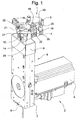
- Fig. 1 shows the inventive cutter head 1 with drive 2.
- the cutter head 1 consists of an upper part 3 and a lower part 4, which are linearly movable.
- the linear movement is generated by means of the drive 2, wherein the rotational movement of a motor 5 is converted into a linear movement of the upper / lower part 3,4.
- a linear unit 6 is housed in a housing 7 with cover 8.
- the Linear unit 6 is protected against insulation residues and strand residues by means of a movable cap 9 and by means of a bellows 10.
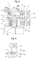
- Fig. 2 shows the drive 2 with the housing 7 open and details of the linear unit 6.
- the rotational movement of the motor 5 is transmitted to a pinion 11 which is engaged with a first rack 12 and a non-visible second rack.
- the first rack 12 is part of a first arm 13, the second rack is part of a second arm 14.
- the racks or the boom 13,14 are moved by means of pinion 11 in opposite directions.
- the first, in cross-section triangular boom 13 is guided by means of a housing 7 arranged on the first linear guide 15.
- the second, in cross-section triangular boom 14 is guided by means of a housing 7 arranged on the second linear guide 16.
- the upper part 3 of the cutter head 1 is connected to the first arm 13.
- the lower part 4 of the cutter head 1 is connected to the second arm 14.
- the position of the first jib 13 and the second jib 14 is detected by means of a measuring device 17.
- a measuring device 17 For example, by means of an optical system scanning a glass measuring rod, wherein the glass measuring rod carries out the movement of one of the arms 13, 14.
- a measuring device 17 operating on the magnetic or capacitive principle is also possible).
- Fig. 3 shows the cutter head 1 in the open position and Fig. 4 shows the cutter head 1 in the closed position.
- the upper part 3 of the cutter head 1 consists of at least one separating knife 18, a first stripping knife 19, a second stripping knife 20, a first cutting edge 21, a working on the piezoelectric principle Force measuring device 22 and a first holding plate 23.
- the lower part 4 of the cutter head 1 consists of at least one cutting knife 24, a third stripping blade 25, a fourth stripping blade 26, a second blade 27 and a second holding plate 28.
- the cap 9 is connected to a the second boom 14 connected Bride 29 is arranged. The cap 9 is moved up and down together with the second arm 14, with the first arm 13 penetrating the cap 13.
- the bellows 10 completes the penetration.
- First cutting edge 21, second cutting edge 27 and force measuring device 22 are used for crimp height measurement.
- First holding plate 23 and second holding plate 28 serve the Auszugskraftlim. Stripping residues fall into a bunker 34 shown in FIG
- FIGS. 5 and 6 show the cutter head 1 in a crimp height measurement.
- the force measuring device 22 is initialized to zero in the position shown in FIG. 4 and the position of the first arm 13 and of the second arm 14 is detected by means of the measuring device 17. Thereafter, the cutter head 1 is opened and a cable 30 consisting of a conductor 30.1 and an insulation 30.2 with a crimp contact 31 is placed between the first cutting edge 21 and the second cutting edge 27. Then, the cutter head 1 is delivered until the force measuring device 22 detects a force increase, which triggers a re-detection of the current position of the first boom 13 and the second boom 14. The difference between the two positions gives the crimp height CH. As shown in Fig. 6, the crimp height CH refers to the wire crimp 32 of the crimp contact 31. The insulation crimp 33 of the crimp contact 31 is secondary to the crimp height measurement.
- the cutter head 1 is designed so that it can be operated from the front side shown as well as from the back with leading or trailing cable ends.
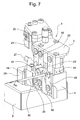
- FIG. 7 shows the cutter head 1 in a pull-out force measurement in which the first holding plate 23 and the second holding plate 28 hold the crimp contact 31.
- the cable 30 with crimp contact 31 zutemde gripper performs with limited current from a linear movement.
- the current limit corresponds to the pull-out force AK. Failure to reach the pull-out force AK or the current limit means that the crimped connection has not withstood the required pull-out force AK, the wire crimp 32 and / or the insulation crimp 33 is faulty.
- the cutter head 1 has no stripping knives 19, 20, 25, 26. If permitted by the cable 30, the conductor insulation 30.2 can be cut by means of separating knives 18, 24 (V-shaped knives cut the insulation at four points) and the insulation residue is removed.
Description
Die Erfindung betrifft einen Messerkopf einer Trenn- und Abisoliervorrichtung für eine Kabelbearbeitungsmaschine bestehend aus einem Oberteil mit mindestens einem Messer und aus einem Unterteil mit mindestens einem Messer und bestehend aus einem Oberteil und Unterteil antreibenden Antrieb.The invention relates to a cutter head of a separating and stripping device for a cable processing machine consisting of an upper part with at least one knife and a lower part with at least one knife and consisting of an upper part and lower part driving drive.
Aus der Patentschrift
Nachteilig bei der bekannten Einrichtung ist der Platzbedarf der Antriebe im Messerkopfbereich. Ausserdem müssen Messungen am Kabel ausserhalb der Maschine durchgeführt werden.A disadvantage of the known device is the space requirement of the drives in the cutter head area. In addition, measurements must be made on the cable outside the machine.
Hier will die Erfindung Abhilfe schaffen. Die Erfindung, wie sie in Anspruch 1 gekennzeichnet ist, löst die Aufgabe, die Nachteile der bekannten Einrichtung zu vermeiden und einen Messerkopf vorzuschlagen, der vielseitig verwendbar ist.The invention aims to remedy this situation. The invention, as characterized in
Vorteilhafte Weiterbildungen der Erfindung sind in den abhängigen Patentansprüchen angegeben.Advantageous developments of the invention are specified in the dependent claims.
Die durch die Erfindung erreichten Vorteile sind im wesentlichen darin zu sehen, dass ausser der Kabeltrennung und der Kabelabisolierung weitere der Kabelbearbeitung dienende Arbeiten durchführbar sind. Beispielsweise ist mit dem erfindungsgemässen Messerkopf die Höhe des Crimpkontaktes im Bereich des Drahtcrimps messbar. Im weiteren kann mit dem erfindungsgemässen Messerkopf beispielsweise die Kraft zum Ausziehen des Kabels aus dem Crimpkontakt gemessen werden. Die erweiterten Funktionen des Messerkopfes erlauben im gesamten kürzere Bearbeitungszeiten, weil die bisher ausserhalb der Kabelbearbeitungsmaschine durchgeführten Hilfsfunktionen entfallen. Die Auszugskraftmessung kann beispielsweise mittels des Stromes des die Linearbewegung des Kabelgreifers ausführenden Motors durchgeführt werden. Zur Crimphöhenmessung ist beispielsweise lediglich eine Kraftmesseinrichtung mit Piezoelementen notwendig, wobei die Crimphöhe aus dem Kraftanstieg der Piezoelemente und der Position der Messerkopfhälften bestimmbar ist.The advantages achieved by the invention are essentially to be seen in the fact that in addition to the cable separation and the cable stripping further work serving the cable processing work can be performed. For example, the height of the crimp contact in the region of the wire crimp can be measured with the knife head according to the invention. Furthermore, with the knife head according to the invention, for example, the force for pulling the cable out of the crimp contact can be measured. The extended functions of the cutter head allow shorter overall processing times, because the previously performed outside the cable processing machine auxiliary functions omitted. The pull-out force measurement can be carried out, for example, by means of the current of the motor carrying out the linear movement of the cable gripper. For crimp height measurement, for example, only one force measuring device with piezo elements is necessary, wherein the crimp height can be determined from the increase in force of the piezo elements and the position of the cutter head halves.
Die üblicherweise beim Einrichten und gelegentlich während der Produktion erfassten Messdaten können gespeichert und zur Qualitätssicherung weiterverwendet werden.The measurement data usually collected during setup and occasionally during production can be saved and used for quality assurance purposes.
Der erfindungsgemässe Messerkopf kann in Kabelbearbeitungsmaschinen mit linearer Kabelzuführung oder in Kabelbearbeitungsmaschinen mit Schwenkarmzuführung verwendet werden.The knife head according to the invention can be used in cable processing machines with linear cable feed or in cable processing machines with swivel arm feed.
Ausser den schneidenden Funktionen wie beipielsweise Trennen oder Abisolieren kann der erfindungsgemässe Messerkopf auch nichtschneidende Funktionen wie beispielsweise Messen der Crimphöhe oder Messen der Auszugskraft ausführen. Der Messerkopf wird linear zugestellt und kommt mit einem Antrieb aus, wobei der unten angeordnete Antrieb den Zugang zu anderen Modulen der Kabelbearbeitungsmaschine erleichtert.Apart from the cutting functions, such as for example separating or stripping, the knife head according to the invention can also perform non-cutting functions, such as measuring the crimp height or measuring the pull-out force. The knife head becomes linear delivered and comes with a drive, the bottom drive arranged to facilitate access to other modules of the cable processing machine.
Anhand der beiliegenden Figuren wird die vorliegende Erfindung näher erläutert.Reference to the accompanying figures, the present invention will be explained in more detail.
Es zeigen:
- Fig. 1
einen erfindungsgemässen Messerkopf mit Antrieb, - Fig. 2
den Antrieb mit geöffnetem Gehäuse, - Fig. 3
den Messerkopf in geöffneter Stellung, - Fig. 4
den Messerkopf in geschlossener Stellung, - Fig. 5 und Fig. 6
den Messerkopf bei einer Crimphöhenmessung und - Fig. 7
den Messerkopf bei einer Auszugskraftmessung.
- Fig. 1
an inventive cutter head with drive, - Fig. 2
the drive with the housing open, - Fig. 3
the cutterhead in open position, - Fig. 4
the cutter head in closed position, - Fig. 5 and Fig. 6
the knife head in a crimp height measurement and - Fig. 7
the knife head in a pull-out force measurement.
Fig. 1 zeigt den erfindungsgemässen Messerkopf 1 mit Antrieb 2. Der Messerkopf 1 besteht aus einem Oberteil 3 und einem Unterteil 4, die linear bewegbar sind. Die Linearbewegung wird mittels des Antriebes 2 erzeugt, wobei die Rotationsbewegung eines Motors 5 in eine Linearbewegung des Ober-/Unterteils 3,4 umgesetzt wird. Eine Lineareinheit 6 ist in einem Gehäuse 7 mit Abdeckung 8 untergebracht. Die Lineareinheit 6 wird vor Isolationsresten und Litzenresten geschützt mittels einer bewegbaren Kappe 9 und mittels eines Faltenbalges 10.Fig. 1 shows the
Fig. 2 zeigt den Antrieb 2 mit geöffnetem Gehäuse 7 und Einzelheiten der Lineareinheit 6. Die Rotationsbewegung des Motors 5 wird auf ein Zahnritzel 11 übertragen, das im Eingriff steht mit einer ersten Zahnstange 12 und einer nicht sichtbaren zweiten Zahnstange. Die erste Zahnstange 12 ist Teil eines ersten Auslegers 13, die zweite Zahnstange ist Teil eines zweiten Auslegers 14. Die Zahnstangen bzw. die Ausleger 13,14 werden mittels Zahnritzel 11 gegenläufig bewegt. Der erste, im Querschnitt dreieckförmige Ausleger 13 ist mittels einer am Gehäuse 7 angeordneten ersten Linearführung 15 geführt. Der zweite, im Querschnitt dreieckförmige Ausleger 14 ist mittels einer am Gehäuse 7 angeordneten zweiten Linearführung 16 geführt. Der Oberteil 3 des Messerkopfes 1 ist mit dem ersten Ausleger 13 verbunden. Der Unterteil 4 des Messerkopfes 1 ist mit dem zweiten Ausleger 14 verbunden. Die Position des ersten Auslegers 13 bzw. des zweiten Auslegers 14 wird mittels einer Messeinrichtung 17 erfasst. (Beispielsweise mittels einer einen Glasmessstab abtastenden Optik, wobei der Glasmessstab die Bewegung eines der Ausleger 13,14 ausführt. Eine auf dem magnetischen oder kapazitiven Prinzip arbeitende Messeinrichtung 17 ist auch möglich).Fig. 2 shows the
Fig. 3 zeigt den Messerkopf 1 in geöffneter Stellung und Fig. 4 zeigt den Messerkopf 1 in geschlossener Stellung. Der Oberteil 3 des Messerkopfes 1 besteht aus mindestens einem Trennmesser 18, einem ersten Abisoliermesser 19, einem zweiten Abisoliermesser 20, einer ersten Schneide 21, einer auf dem Piezo Prinzip arbeitenden Kraftmesseinrichtung 22 und aus einer ersten Halteplatte 23. Der Unterteil 4 des Messerkopfes 1 besteht aus mindestens einem Trennmesser 24, einem dritten Abisoliermesser 25, einem vierten Abisoliermesser 26, einer zweiten Schneide 27 und aus einer zweiten Halteplatte 28. Die Kappe 9 ist an einer mit dem zweiten Ausleger 14 verbundenen Bride 29 angeordnet. Die Kappe 9 wird zusammen mit dem zweiten Ausleger 14 auf und ab bewegt, wobei der erste Ausleger 13 die Kappe 13 durchdringt. Der Faltenbalg 10 schliesst die Durchdringung ab. Erste Schneide 21, zweite Schneide 27 und Kraftmesseinrichtung 22 dienen der Crimphöhenmessung. Erste Halteplatte 23 und zweite Halteplatte 28 dienen der Auszugskraftmessung. Abisolierreste fallen in einen in Fig. 7 gezeigten Bunker 34.Fig. 3 shows the
Fig. 5 und Fig. 6 zeigen den Messerkopf 1 bei einer Crimphöhenmessung. Die Kraftmesseinrichtung 22 wird in der in Fig. 4 gezeigten Stellung auf Null initialisiert und die Position des ersten Auslegers 13 bzw. des zweiten Auslegers 14 mittels der Messeinrichtung 17 erfasst. Danach wird der Messerkopf 1 geöffnet und ein aus einem Leiter 30.1 und einer Isolation 30.2 bestehendes Kabel 30 mit Crimpkontakt 31 zwischen die erste Schneide 21 und zweite Schneide 27 gelegt. Dann wird der Messerkopf 1 zugestellt bis die Kraftmesseinrichtung 22 einen Kraftanstieg feststellt, was eine erneute Erfassung der momentanen Position des ersten Auslegers 13 bzw. des zweiten Auslegers 14 auslöst. Die Differenz der beiden Positionen ergibt die Crimphöhe CH. Wie in Fig. 6 gezeigt bezieht sich die Crimphöhe CH auf den Drahtcrimp 32 des Crimpkontaktes 31. Der Isolationscrimp 33 des Crimpkontaktes 31 ist für die Crimphöhenmessung sekundär.FIGS. 5 and 6 show the
Der Messerkopf 1 ist so ausgelegt, dass er von der gezeigten Frontseite wie auch von der Rückseite mit vorauseilenden bzw. nacheilenden Kabelenden bedient werden kann.The
Fig. 7 zeigt den Messerkopf 1 bei einer Auszugskraftmessung, bei der die erste Halteplatte 23 und die zweite Halteplatte 28 den Crimpkontakt 31 festhalten. Der das Kabel 30 mit Crimpkontakt 31 zubringende Greifer führt mit begrenztem Strom eine Linearbewegung aus. Die Stromgrenze entspricht der Auszugskraft AK. Nichterreichen der Auszugskraft AK bzw. der Stromgrenze bedeutet, dass die Crimpverbindung der geforderten Auszugskraft AK nicht standgehalten hat, der Drahtcrimp 32 und/oder der Isolationscrimp 33 ist fehlerhaft.FIG. 7 shows the
In einer weiteren Ausführungsvariante weist der Messerkopf 1 keine Abisoliermesser 19,20,25,26 auf. Sofern vom Kabel 30 her zulässig, kann die Leiterisolation 30.2 mittels Trennmesser 18,24 eingeschnitten werden (V-förmige Messer schneiden die Isolation an vier Punkten ein) und der Isolationsrest abgezogen werden.In a further embodiment, the
Claims (4)
- Cutter head (1) of a cutting and stripping device for a cable processing apparatus comprising an upper part (3) with at least one cutter (18, 19, 20) and a lower part (4) with at least one cutter (24, 25, 26) and a drive (2) that drives the upper part (3) and the lower part (4),
characterized in that
by means of a linear unit (6) the rotational movement of a drive motor (5) can be converted into a linear movement of the upper part (3) and of the lower part (4), the cutter head (1) that has the cutting blade (18, 24) and insulation stripping blade (19, 20, 25, 26) is linearly feedable, and in that, for the purpose of measuring a crimp height (CH), provided at the cutter head (1) are a force measuring device (22), a first blade (21) and a second blade (27) and/or provided on the cutter head (1) for the purpose of measuring a pull-out force (AK) are a first holding plate (23) and a second holding plate (28). - Cutter head according to Claim 1,
characterized in that
the force measuring device (22) and the first blade (21) are arranged on the upper part (3) and the second blade (27) on the lower part (4), a crimp contact (31) in the force measuring device (22) that is arranged between the blades (21, 27) generating an increase in force. - Cutter head according to Claim 2,
characterized in that
with the force signal of the force-measuring device (22) and with a position signal of a measuring device (17) that detects the position of the upper part (3) and of the lower part (4) the crimp height (CH) of the crimp contact (31) can be determined. - Cutter head according to Claim 1,
characterized in that
arranged on the upper part (3) is the first holding plate (23) and on the lower part (4) the second holding plate (28), it being possible with the linear feeding movement to hold by means of the holding plates (23, 28) a crimp contact (31) that is arranged between the holding plates (23, 28) for the purpose of measuring the pull-out force (AK).
Priority Applications (1)
| Application Number | Priority Date | Filing Date | Title |
|---|---|---|---|
| EP20040020706 EP1515410B1 (en) | 2003-09-10 | 2004-09-01 | Cutter head of a cutting and stripping device for a cable processing apparatus |
Applications Claiming Priority (3)
| Application Number | Priority Date | Filing Date | Title |
|---|---|---|---|
| EP03405664 | 2003-09-10 | ||
| EP03405664 | 2003-09-10 | ||
| EP20040020706 EP1515410B1 (en) | 2003-09-10 | 2004-09-01 | Cutter head of a cutting and stripping device for a cable processing apparatus |
Publications (3)
| Publication Number | Publication Date |
|---|---|
| EP1515410A2 EP1515410A2 (en) | 2005-03-16 |
| EP1515410A3 EP1515410A3 (en) | 2006-05-17 |
| EP1515410B1 true EP1515410B1 (en) | 2007-10-31 |
Family
ID=34137616
Family Applications (1)
| Application Number | Title | Priority Date | Filing Date |
|---|---|---|---|
| EP20040020706 Active EP1515410B1 (en) | 2003-09-10 | 2004-09-01 | Cutter head of a cutting and stripping device for a cable processing apparatus |
Country Status (1)
| Country | Link |
|---|---|
| EP (1) | EP1515410B1 (en) |
Cited By (4)
| Publication number | Priority date | Publication date | Assignee | Title |
|---|---|---|---|---|
| CN100583581C (en) * | 2008-05-13 | 2010-01-20 | 倪君权 | Rotary knife rack structure for coaxial-cable wire stripper |
| DE102009009743A1 (en) | 2009-02-19 | 2010-08-26 | BÖWE-ELEKTRIK GmbH | Cable, has banding and/or filler material consisting of substances, which are dissolved in solvent e.g. water, where material solidarity of substances is reduced by solvent without damaging other materials present in cable |
| US9090036B2 (en) | 2009-04-02 | 2015-07-28 | Schleuniger Holding Ag | Crimping press |
| EP3035460A1 (en) | 2014-12-17 | 2016-06-22 | Komax Holding AG | Cutting unit for stripping insulation from cables |
Families Citing this family (6)
| Publication number | Priority date | Publication date | Assignee | Title |
|---|---|---|---|---|
| DE102005012963B3 (en) * | 2005-03-21 | 2006-11-02 | Sle Electronic Gmbh | Monitoring and control method for cable processing apparatus involves monitoring and controlling cable processing apparatus based on salient position for close fitting of insulated construction units or wiring or complete cable splitting |
| EP1780846B1 (en) * | 2005-10-27 | 2009-03-18 | komax Holding AG | Measuring head and method for determination of crimp height of a conductor |
| EP2797182B1 (en) | 2013-04-24 | 2020-06-17 | Komax Holding AG | Cable conversion device for cutting, stripping and converting a cable with crimp contacts |
| RS61248B1 (en) | 2016-10-18 | 2021-01-29 | Komax Holding Ag | Method and device for insulating a cable with a multi-layer sheath |
| CN107845985B (en) * | 2017-11-23 | 2019-08-06 | 国网山东省电力公司德州供电公司 | A kind of punck-down block of power engineering field |
| CN110364908B (en) * | 2019-08-14 | 2020-11-27 | 深圳市鑫和兴机械设备有限公司 | Intelligent terminal crimping machine for electronic circuit terminal and method thereof |
Family Cites Families (2)
| Publication number | Priority date | Publication date | Assignee | Title |
|---|---|---|---|---|
| EP0623982B1 (en) * | 1993-05-06 | 1996-11-27 | Komax Holding Ag | Cutting and stripping device for a cable processing machine |
| JP3156841B2 (en) * | 1996-06-12 | 2001-04-16 | 矢崎総業株式会社 | Control method of terminal crimping device |
-
2004
- 2004-09-01 EP EP20040020706 patent/EP1515410B1/en active Active
Cited By (4)
| Publication number | Priority date | Publication date | Assignee | Title |
|---|---|---|---|---|
| CN100583581C (en) * | 2008-05-13 | 2010-01-20 | 倪君权 | Rotary knife rack structure for coaxial-cable wire stripper |
| DE102009009743A1 (en) | 2009-02-19 | 2010-08-26 | BÖWE-ELEKTRIK GmbH | Cable, has banding and/or filler material consisting of substances, which are dissolved in solvent e.g. water, where material solidarity of substances is reduced by solvent without damaging other materials present in cable |
| US9090036B2 (en) | 2009-04-02 | 2015-07-28 | Schleuniger Holding Ag | Crimping press |
| EP3035460A1 (en) | 2014-12-17 | 2016-06-22 | Komax Holding AG | Cutting unit for stripping insulation from cables |
Also Published As
| Publication number | Publication date |
|---|---|
| EP1515410A3 (en) | 2006-05-17 |
| EP1515410A2 (en) | 2005-03-16 |
Similar Documents
| Publication | Publication Date | Title |
|---|---|---|
| EP3089294B1 (en) | Cable processing device and method for removing a screen film from a shielded, multi-core round cable | |
| EP1515410B1 (en) | Cutter head of a cutting and stripping device for a cable processing apparatus | |
| EP1780846B1 (en) | Measuring head and method for determination of crimp height of a conductor | |
| DE102007040278A1 (en) | Sheet-like goods e.g. paper, stack cutting device for use in printing system, has contact surfaces with supporting frame, and adjusting unit adjusting angle between cutting plane of blade and front side of stack section, which is to be cut | |
| DE1465095C3 (en) | Method and device for the electrical connection of two connecting pins located on a circuit board | |
| EP2656984B1 (en) | Cutting system with cutting machine and an alignment device | |
| EP1070374B1 (en) | Stripping device and a method for stripping | |
| AT517190B1 (en) | Machine for cutting panels | |
| DE955330C (en) | Stripping pliers | |
| EP3243617B1 (en) | Cutting machine | |
| EP0245726B1 (en) | Device for machining the edge of a spectacle glass | |
| EP0438737A2 (en) | Apparatus for cutting stacked material in sheet form with a lateral stop and a pusher movable against the lateral stop to align the material to be cut | |
| EP0989637A1 (en) | Device for assembling a cable | |
| WO1990000499A1 (en) | Arrangement with frame for removing binding surrounding a bale | |
| DE102020202201B4 (en) | Folding device for bending a workpiece and a method for operating such a folding device | |
| CH697849B1 (en) | A method for monitoring and / or controlling a wire-processing device and cable processing apparatus. | |
| EP3243616A1 (en) | Cutting machine | |
| DE2505739A1 (en) | Pliers for removing cable insulation - has receptacle attached to jaws to retain removed cable insulation | |
| DE19827782C1 (en) | Device for cutting stacked, leafy material | |
| DE3144281A1 (en) | Method and device for preparing the connecting ends of moving electrical cables having three cores | |
| DE3808665C2 (en) | Cutting device for fine wires | |
| WO1998006154A1 (en) | Device for fixing single wires into idc contacts | |
| DE2454437A1 (en) | Insulation stripping and cutting machine for flat cables - uses compressed air to blow cutting waste into outlet channel | |
| EP4302947A1 (en) | Cutting machine | |
| EP3858507A1 (en) | Folding device for bending a workpiece and method for operating such a folding device |
Legal Events
| Date | Code | Title | Description |
|---|---|---|---|
| PUAI | Public reference made under article 153(3) epc to a published international application that has entered the european phase |
Free format text: ORIGINAL CODE: 0009012 |
|
| AK | Designated contracting states |
Kind code of ref document: A2 Designated state(s): AT BE BG CH CY CZ DE DK EE ES FI FR GB GR HU IE IT LI LU MC NL PL PT RO SE SI SK TR |
|
| AX | Request for extension of the european patent |
Extension state: AL HR LT LV MK |
|
| PUAL | Search report despatched |
Free format text: ORIGINAL CODE: 0009013 |
|
| AK | Designated contracting states |
Kind code of ref document: A3 Designated state(s): AT BE BG CH CY CZ DE DK EE ES FI FR GB GR HU IE IT LI LU MC NL PL PT RO SE SI SK TR |
|
| AX | Request for extension of the european patent |
Extension state: AL HR LT LV MK |
|
| RIC1 | Information provided on ipc code assigned before grant |
Ipc: H01R 43/052 20060101ALI20060329BHEP Ipc: H02G 1/12 20060101AFI20041215BHEP Ipc: H01R 43/048 20060101ALI20060329BHEP |
|
| 17P | Request for examination filed |
Effective date: 20061028 |
|
| 17Q | First examination report despatched |
Effective date: 20061213 |
|
| AKX | Designation fees paid |
Designated state(s): CH DE FR GB IT LI |
|
| GRAP | Despatch of communication of intention to grant a patent |
Free format text: ORIGINAL CODE: EPIDOSNIGR1 |
|
| RTI1 | Title (correction) |
Free format text: CUTTER HEAD OF A CUTTING AND STRIPPING DEVICE FOR A CABLE PROCESSING APPARATUS |
|
| GRAS | Grant fee paid |
Free format text: ORIGINAL CODE: EPIDOSNIGR3 |
|
| GRAA | (expected) grant |
Free format text: ORIGINAL CODE: 0009210 |
|
| AK | Designated contracting states |
Kind code of ref document: B1 Designated state(s): CH DE FR GB IT LI |
|
| REG | Reference to a national code |
Ref country code: GB Ref legal event code: FG4D Free format text: NOT ENGLISH |
|
| REG | Reference to a national code |
Ref country code: CH Ref legal event code: EP |
|
| REF | Corresponds to: |
Ref document number: 502004005349 Country of ref document: DE Date of ref document: 20071213 Kind code of ref document: P |
|
| GBT | Gb: translation of ep patent filed (gb section 77(6)(a)/1977) |
Effective date: 20071205 |
|
| REG | Reference to a national code |
Ref country code: CH Ref legal event code: NV Representative=s name: INVENTIO AKTIENGESELLSCHAFT |
|
| ET | Fr: translation filed | ||
| PLBE | No opposition filed within time limit |
Free format text: ORIGINAL CODE: 0009261 |
|
| STAA | Information on the status of an ep patent application or granted ep patent |
Free format text: STATUS: NO OPPOSITION FILED WITHIN TIME LIMIT |
|
| 26N | No opposition filed |
Effective date: 20080801 |
|
| PGFP | Annual fee paid to national office [announced via postgrant information from national office to epo] |
Ref country code: GB Payment date: 20080918 Year of fee payment: 5 |
|
| GBPC | Gb: european patent ceased through non-payment of renewal fee |
Effective date: 20090901 |
|
| PG25 | Lapsed in a contracting state [announced via postgrant information from national office to epo] |
Ref country code: GB Free format text: LAPSE BECAUSE OF NON-PAYMENT OF DUE FEES Effective date: 20090901 |
|
| REG | Reference to a national code |
Ref country code: FR Ref legal event code: PLFP Year of fee payment: 13 |
|
| REG | Reference to a national code |
Ref country code: FR Ref legal event code: PLFP Year of fee payment: 14 |
|
| PGFP | Annual fee paid to national office [announced via postgrant information from national office to epo] |
Ref country code: IT Payment date: 20170926 Year of fee payment: 14 Ref country code: DE Payment date: 20170928 Year of fee payment: 14 Ref country code: FR Payment date: 20170928 Year of fee payment: 14 |
|
| REG | Reference to a national code |
Ref country code: DE Ref legal event code: R119 Ref document number: 502004005349 Country of ref document: DE |
|
| PG25 | Lapsed in a contracting state [announced via postgrant information from national office to epo] |
Ref country code: DE Free format text: LAPSE BECAUSE OF NON-PAYMENT OF DUE FEES Effective date: 20190402 Ref country code: IT Free format text: LAPSE BECAUSE OF NON-PAYMENT OF DUE FEES Effective date: 20180901 |
|
| PG25 | Lapsed in a contracting state [announced via postgrant information from national office to epo] |
Ref country code: FR Free format text: LAPSE BECAUSE OF NON-PAYMENT OF DUE FEES Effective date: 20180930 |
|
| PGFP | Annual fee paid to national office [announced via postgrant information from national office to epo] |
Ref country code: CH Payment date: 20231001 Year of fee payment: 20 |