EP1515275A2 - Vorrichtung, Verfahren, sowie integrierter Schaltkreis zur Bildsegmentierung - Google Patents
Vorrichtung, Verfahren, sowie integrierter Schaltkreis zur Bildsegmentierung Download PDFInfo
- Publication number
- EP1515275A2 EP1515275A2 EP04019070A EP04019070A EP1515275A2 EP 1515275 A2 EP1515275 A2 EP 1515275A2 EP 04019070 A EP04019070 A EP 04019070A EP 04019070 A EP04019070 A EP 04019070A EP 1515275 A2 EP1515275 A2 EP 1515275A2
- Authority
- EP
- European Patent Office
- Prior art keywords
- cell
- cells
- ignited
- image segmentation
- region
- Prior art date
- Legal status (The legal status is an assumption and is not a legal conclusion. Google has not performed a legal analysis and makes no representation as to the accuracy of the status listed.)
- Withdrawn
Links
Images











Classifications
-
- G—PHYSICS
- G06—COMPUTING OR CALCULATING; COUNTING
- G06T—IMAGE DATA PROCESSING OR GENERATION, IN GENERAL
- G06T1/00—General purpose image data processing
-
- G—PHYSICS
- G06—COMPUTING OR CALCULATING; COUNTING
- G06T—IMAGE DATA PROCESSING OR GENERATION, IN GENERAL
- G06T7/00—Image analysis
- G06T7/20—Analysis of motion
-
- G—PHYSICS
- G06—COMPUTING OR CALCULATING; COUNTING
- G06T—IMAGE DATA PROCESSING OR GENERATION, IN GENERAL
- G06T7/00—Image analysis
- G06T7/10—Segmentation; Edge detection
- G06T7/11—Region-based segmentation
-
- G—PHYSICS
- G06—COMPUTING OR CALCULATING; COUNTING
- G06V—IMAGE OR VIDEO RECOGNITION OR UNDERSTANDING
- G06V10/00—Arrangements for image or video recognition or understanding
- G06V10/20—Image preprocessing
- G06V10/26—Segmentation of patterns in the image field; Cutting or merging of image elements to establish the pattern region, e.g. clustering-based techniques; Detection of occlusion
- G06V10/267—Segmentation of patterns in the image field; Cutting or merging of image elements to establish the pattern region, e.g. clustering-based techniques; Detection of occlusion by performing operations on regions, e.g. growing, shrinking or watersheds
-
- G—PHYSICS
- G06—COMPUTING OR CALCULATING; COUNTING
- G06V—IMAGE OR VIDEO RECOGNITION OR UNDERSTANDING
- G06V10/00—Arrangements for image or video recognition or understanding
- G06V10/94—Hardware or software architectures specially adapted for image or video understanding
- G06V10/955—Hardware or software architectures specially adapted for image or video understanding using specific electronic processors
-
- G—PHYSICS
- G06—COMPUTING OR CALCULATING; COUNTING
- G06T—IMAGE DATA PROCESSING OR GENERATION, IN GENERAL
- G06T2200/00—Indexing scheme for image data processing or generation, in general
- G06T2200/28—Indexing scheme for image data processing or generation, in general involving image processing hardware
-
- G—PHYSICS
- G06—COMPUTING OR CALCULATING; COUNTING
- G06T—IMAGE DATA PROCESSING OR GENERATION, IN GENERAL
- G06T2207/00—Indexing scheme for image analysis or image enhancement
- G06T2207/10—Image acquisition modality
- G06T2207/10016—Video; Image sequence
Definitions
- the present invention relates to an image segmentation apparatus for image processing, which recognizes an image or detects movement in real time, an image segmentation method, and an image segmentation integrated circuit.
- image segmentation individual objects (e.g., mobile objects such as a human face and car) are taken from a complicated natural image taken as an input, and this processing is basic and indispensable for performing image processing which is object-based processing, such as image recognition and movement detection.
- object-based processing such as image recognition and movement detection.
- An object of the present invention is to propose a color/gray-scale image segmentation architecture which realizes real-time processing at a lower power consumption even with a large-scaled image, and to provide an image segmentation apparatus which can be realized by a digital circuit using the architecture, and an image segmentation integrated circuit.
- an image segmentation method in which a region belonging to the same category is specified from an input image by a pixel unit to identify an image segmentation region, the method characterized by comprising:
- an image segmentation apparatus in which a region belonging to the same category is specified from an input image by a pixel unit to identify an image segmentation region, and an image of an optional image segmentation region is selectively output, the apparatus characterized by comprising:
- an image segmentation method in which a region belonging to the same category is specified from an input image by a pixel unit to identify an image segmentation region, the method characterized by comprising:
- an image segmentation apparatus in which a region belonging to the same category is specified from an input image by a pixel unit to identify an image segmentation region, and an image of an optional image segmentation region is selectively output, the apparatus characterized by comprising:
- an integrated circuit comprising all circuits integrated for image segmentation in which a region belonging to the same category is specified from an input image by a pixel unit to identify an image segmentation region, and an image of an optional image segmentation region is selectively output, the circuit characterized by comprising:
- an integrated circuit comprising all circuits integrated for image segmentation in which a region belonging to the same category is specified from an input image by a pixel unit to identify an image segmentation region, and an image of an optional image segmentation region is selectively output, the circuit characterized by comprising:
- an image segmentation apparatus and image segmentation integrated circuit the above-described methods are realized by hardware.
- the present inventors have newly introduced systems such as the boundary active only (BAO) scheme and subdivided image approach (SIA) into a real-time image segmentation architecture of a cell network base proposed in Documents 4 to 6 and 10, and have further combined the architecture with a low power consumption technique in another circuit level. Accordingly, it is possible to realize reduction of the power consumption by about 75% as compared with the conventional technique without losing a real-time processing property.
- BAO boundary active only
- SIA subdivided image approach
- SIA subdivided image approach
- a proposed image segmentation architecture is based on an image segmentation algorithm/architecture which have been heretofore proposed by the present inventors [see Documents 4 to 6, 10, for example]. In estimates by simulations which have been heretofore performed, high-speed processing of a VGA size image (640 ⁇ 480 pixels) at about 500 ⁇ sec at 10 MHz or less can be expected.
- FIG. 1 is a flowchart showing a flow of processing of the image segmentation algorithm for use in the present invention.
- the algorithm shown in FIG. 1 comprises six processes: (a) initialization; (b) self-ignitable cell detection; (c) self-ignition; (d) ignitable cell detection; (e) ignition; and (f) extinguishment.
- cells corresponding to pixels operate in parallel based on a coupling weight among eight pixels adjacent to one another.
- the cell corresponding to each pixel takes a non-ignited, self-ignitable, or ignited state.
- a coupling weight W ik based on the pixel value of a cell (pixel) k ⁇ N(i) adjacent to the cell (pixel) i is calculated.
- N(i) indicates a set of cells adjacent to the cell i (e.g., a set of eight adjacent cells).
- the leader cell is a candidate of a start point to start the processing in the subsequent image segmentation.
- the value of a global suppressor z is defined as the logical sum (OR) of all z i based on this variable z i .
- a self-ignitable cell is selected from the leader cells which are not ignited yet.
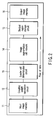
- the proposed architecture is based on the image segmentation algorithm on the basis of the above-described cell network, and the hardware of the image segmentation apparatus based on this algorithm comprises four pipeline stages as shown in FIG. 2.
- input image data is successively recorded in an input image memory 11.
- a coupling weight calculation circuit 12 of a first stage image data of a processing object is taken from the input image memory 11, and the coupling weight is calculated based on a difference of luminance between the adjacent pixels (difference of luminance of RGB in a color image).
- a leader cell determination circuit 13 of a second stage the leader cell constituting a start point of region growth of image segmentation is determined based on the calculated coupling weight.
- an image segmentation cell network 14 which is a core circuit of image segmentation, the image segmentation is performed with respect to a plurality of pixels in parallel by the coupling weight and information of the leader cell.
- the image segmentation cell network 14 has a cell network structure in which one pixel is associated with one cell P ij , and vertical and horizontal coupling weight registers WRv ji , WRh ij are alternately arranged between the cells in an array form to realize a small area.
- Each cell shifts to the ignited, self-ignited, and extinguished states in parallel based on the state of the adjacent cell and the coupling weight.
- one of a plurality of leader cells is self-ignited, it is successively decided based on the coupling weight of the adjacent cell whether or not the cell is ignitable. If conditions are satisfied, the cell is ignited. This ignition is performed as if the region expanded from the leader cell.
- a global suppressor circuit detects that there is not any ignitable cell. By this detection, it is decided that the image segmentation of one region is completed, and the extinguishing is performed with respect to the ignited cell. The above-described processing is repeated until all the leader cells are ignited, and accordingly the image segmentation of all the regions is completed.
- a label number of each divided region subjected to the image segmentation in the image segmentation cell network 14, and the number is recorded in an image memory 16 together with processed image data.
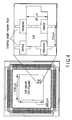
- the present inventors designed/fabricated a test chip of the image segmentation cell network 14 which is the above-described core circuit using a 0.35 ⁇ m CMOS technology. A chip picture and a partial enlarged view are shown in FIG. 4. To realize the small area, all active cells and coupling weight register blocks were designed by full custom.
- FIG. 6 shows a schematic diagram of the BAO scheme proposed by the present invention.
- the image segmentation algorithm of the present invention being of a region growth type is effectively used.
- the respective cells operate in parallel, and the sum of coupling weights is calculated in accordance with the state of the adjacent cell.
- the sum is not less than the threshold value ⁇ Z , the cell shifts to the ignited state. Therefore, when the number of cells (number of pixels) increases, the number of cells operating simultaneously increases, and the power consumption increases in general.
- each cell performs state transition in parallel. Additionally, in actual, the state transition of the cell is performed in a case where "as a result of calculation of the sum of the coupling weights, the sum is not less than the threshold value ⁇ Z " and the cell constitutes the boundary of the region growth of the ignited cell from the leader cell as the start point (boundary of the region growth of FIG. 6). In another case, since the sum of the coupling weights does not change, the state of the cell does not change.
- the BAO scheme in the present invention is a method of automatically controlling the simultaneously operating cells and coupling weight registers so as to decrease the numbers of the cells and registers so that the power consumption is reduced, paying attention to the above-described respects.
- FIGS. 7A and 7B are block diagrams showing a circuit constitution of the cell according to conventional methods
- FIG. 8 is a block diagram showing a circuit constitution of a coupling weight register by the conventional method.
- FIG. 7A shows a constitution of a high-speed operation of the cell, in which the coupling weights with eight adjacent cells are calculated in parallel in one cycle (weight parallel architecture).
- FIG. 7B shows a constitution of a high-speed operation of the cell, in which the coupling weights with eight adjacent cells are successively calculated in nine cycles (weight serial architecture).
- a signal x i (1 bit) indicating the ignited state to registers 21 to 24, a variable p i (1 bit) indicating whether or not the self-ignition is possible, a variable n i for a self-ignition permission control signal (1 bit), and a variable l i (1 bit) indicating whether or not the cell is included in a certain divided region subjected to the image segmentation are stored.
- a coupling weight W ik ⁇ x k among eight adjacent cells each encoded in three bits is input, and a decoder 25 decodes the weight in eight bits.
- an adder 26 calculates a sum Si of the coupling weights, and a subtracter 27 subtracts a threshold value ⁇ Z for deciding "whether or not the ignition is possible" from the sum S i (11 bits).
- the subtracter 27 decides S i - ⁇ Z > 0 to output a sign bit indicating a decision result to a control circuit 28.
- the coupling weight W ik ⁇ x k among eight vicinity cells each encoded in three bits and the threshold value ⁇ Z for deciding an "ignitable" state are successively selectively input by input switch of a switch 29.
- a selection result is decoded into eight bits by a decoder 30, and addition/subtraction is successively performed by a serial adder/subtracter 31 and register 32.
- the vertical coupling type in a case where a coupling weight value held in the register includes a coupling weight between the cells in a vertical direction is distinguished from the horizontal coupling type in a case where the value includes a coupling weight between the cells in a horizontal direction.
- the coupling weight register comprises: a switch 41 for switching/outputting the coupling weight value input via a data input port in four systems based on an input control signal; four registers 42 to 45 in which the coupling weight values given from the switch 41 are stored; and an output selection circuit 46 for transferring the coupling weight value to the adjacent image segmentation cell.
- the value of the coupling weight is in the range of 0 to 255 in a case where a pixel value is represented by eight bits. Therefore, in general, the coupling weight register requires eight bits. However, since the number of coupling weight registers is proportional to that of the pixels, the number of bits have a large influence on an area increase. To solve the problem, the coupling weight value of eight bits is encoded into three bits, and stored in the registers 42 to 45. Accordingly, the area of each coupling weight register and a bit width of a wiring required for exchanging data between each coupling weight register and the image segmentation cell can be largely reduced, and the small area can be realized.
- FIGS. 9 and 10 A constitution in a case where the BAO scheme of the present invention is applied to the cell and coupling weight register constituted as described above is shown in FIGS. 9 and 10. It should be noted that in FIGS. 9 and 10, the same parts as those of FIGS. 7A, 7B, and 8 are denoted with the same reference numerals, and redundant description is omitted.
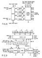
- FIG. 9 is a circuit block diagram in a case where a BAO state detection circuit 33 according to the present invention is added to the cell of the weight parallel architecture shown in FIG. 7A.
- FIG. 10 is a circuit block diagram in a case where the BAO state detection circuit 33 according to the present invention is added to the cell of the weight serial architecture shown in FIG. 7B.
- a clock p_CLK i is supplied as an internal clock inter_CLK i to the respective registers 21 to 24 through the BAO state detection circuit 33.
- the value from the adjacent coupling weight register is controlled by setting an enable signal to the decoder 25 in the weight parallel architecture of FIG. 9 and to the decoder 30 in the weight serial architecture of FIG. 10.
- the decoder 25, adder 26, and subtracter 27 constitutes a combined circuit.
- the input does not change, charge/discharge hardly occurs in a transistor in each circuit, and therefore no power is consumed.
- the value input into the decoder 25 is fixed.
- the input of the switch 29 is set to a fixed value. Accordingly, the condition that the input does not change is satisfied. Therefore, it is possible to reduce the power consumption.
- FIG. 11 shows a constitution example of the BAO state detection circuit 33.
- a first logical sum gate 331 decides Condition 1 by the logical sum of the state signals x k of eight adjacent vicinity cells.
- a second logical sum gate 332 takes in a signal x i , and variable l i from the control circuit 28 to obtain the logical sum, and decides Condition 2.
- a second logical product gate 334 takes a logical product of the enable signal enable and the input clock p_CLK i to produce the internal clock inter_CLK i . Therefore, when the enable signal indicates "0" as described above, the internal clock inter_CLK i of the image segmentation cell stops.
- the mode is shifted to the standby mode by a circuit constitution of a gated clock for stopping the supply of the clock signal to each cell and coupling weight register, and the operations of the cell and coupling weight register are stopped to reduce the power consumption. Since this function is incorporated in each cell and coupling weight register, the power consumption is reduced.
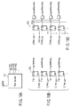
- FIG. 12 is a logic circuit diagram showing a constitution of a row clock control circuit 51 which performs a clock control with respect to the whole image segmentation cell network 14.
- FIG. 12 shows a realization example in a row direction, but a column direction can also be realized in a similar system.
- the image segmentation cell and coupling weight register differ with operated conditions, and are efficiently controlled using separate clock lines WR_CLK i and p_CLK i .
- the row clock control circuit 51 shown in FIG. 12 comprises several gates centering on an operation region control circuit 510.
- the operation region control circuit 510 comprises three components: a row decoder 511 shown in FIG. 13A; a label write row selection circuit 512 shown in FIG. 13B; and a boundary cell active circuit 513 shown in FIG. 13C.
- a row in which the cell ignited by a Z_line i signal of each row exists can be obtained.
- the clock is supplied only to the image segmentation cell of the vicinity (boundary of the region growth) ignited based on the signal.
- a signal of active_row i is set to 1 only in a case where signals of upper/lower rows Z_line i-1 , Z_line i+1 are 1, and the clock CLK is supplied.
- the logical product of information labelrow i of an ignition region detected by the operation region control circuit 510 and a label write signal is taken, and the clock CLK is supplied only to a necessary portion.
- the information of the ignition region is obtained by the label write row selection circuit shown in FIG. 13B.
- Z_line i changes to 1 from 0, that is, when an ignition operation occurs in the row
- 1 is set to the register to store the occurrence of the ignition.
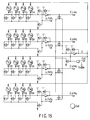
- the signal of the global suppressor is connected as shown in FIG. 15 (4 ⁇ 4 cell network).
- the unnecessary signal from the cell in the standby mode and the supply of the clock are cut to reduce the power consumption. Furthermore, further reduction is realized by omitting calculation of the logical sum of the row in which the cell in the active mode does not exist.
- the subdivided image approach (SIA) is proposed as a method of processing the image in real time with small area/low power consumption with respect to a large-scaled image.
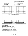
- a large-scaled image (VGA size (640 ⁇ 480 pixels) image in the example) is divided into a plurality of small-scaled blocks (33 ⁇ 25 pixels in the example of FIG. 16), and each block is subjected to the image segmentation using the image segmentation cell network in which the BAO method of the present invention is incorporated. Based on the result, the image segmentation of each block is successively performed in order, and the results are finally put together to perform the whole image segmentation.
- each block is divided in such a manner that a boundary between the blocks overlaps with the adjacent block by at least one or more pixels.
- the pixel included in a region including the image segmentation exists in the portion overlapping with the adjacent block.
- the cell is determined beforehand as the leader cell in the leader cell determination circuit. Accordingly, the image segmentation of the block being processed can be performed using the dividing result in the previously processed block.
- a region number is added as a label in a case where the blocks are included in the same divided region. Therefore, a correspondence table of label numbers attached to the pixels superimposed upon the adjacent block in the boundary between the blocks is updated every block processing.
- the labels of all the regions are output in a stage in which the processing of all the blocks ends, and in this case, the label is changed in such a manner that the same region has the same label number. Accordingly, the result of the whole image segmentation performed for each divided block can be output without any contradiction.
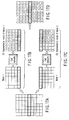
- FIGS. 17A to 17D show simple examples of the image segmentation by block dividing by the SIA.
- the image shown in FIG. 17A is input, the image is divided into Block 1 and Block 2 as shown in FIGS. 17B and 17C, and the image segmentation is performed in each block.
- a label is attached as an image segmentation result to each region, and the label needs to be associated with the same region. Therefore, the block is divided with an overlap by one pixel in the pixels of the boundary portion of each block.
- the labels attached to the pixels of the boundary portion are matched in connecting Block 1 to Block 2 as shown in FIG. 17D.
- the image segmentation of each block is performed basically in accordance with the flowchart of the image segmentation in FIG. 1. Additionally, when one image is divided and processed into a plurality of blocks, as shown in FIG. 18, competition of the label numbers of the divided regions sometimes occurs. In FIG. 18, Labels 4, 5, and 2 are in the same divided region, but different labels are allocated. Then, a flowchart of an SIA image segmentation algorithm which solves this problem is shown in FIG. 19. This algorithm is based on the algorithm of FIG. 1, and processing for label competition is added. Details of the SIA image segmentation algorithm shown in FIG. 19 will be described below.
- step S11 initialization is executed in accordance with an instruction for the image segmentation, the coupling weight indicating similarity between the adjacent pixels is calculated, and the leader cell which is the start point of the image segmentation is determined.
- the cell of a pre-labeled portion (hereinafter referred to as the pre-labeled cell) is forcibly determined as the leader cell (hereinafter referred to as a pre-labeled leader cell). Since the pre-labeled cell is labeled by the previous dividing, the label is read and stored beforehand.
- step S12 it is decided in step S12 whether or not the pre-labeled leader cell exists.
- step S13 the pre-labeled leader cell is ignited to start the image segmentation in the block.
- step S14 it is decided in step S14 whether or not the pre-labeled cell having the same label as that of the ignited pre-labeled leader cell exists.
- the pre-labeled cell is ignited in step S15).
- step S15 When the ignition of step S15 is completed, and it is decided in step S14 that the cell does not exist, it is decided in step S16 whether or not the ignitable cell exists. When it is decided in step S16 that the cell exists, ignition is performed in step S17.
- step S18 it is decided in step S18 whether or not another pre-labeled cell having a different label is ignited by the indicating of step S17.
- step S18 it is decided in step S18 that the cell is not ignited, the process returns to step S16.
- step S19 it is decided in step S19 whether or not the pre-labeled cell having the same label as that of the ignited pre-labeled cell exists.
- step S16 When it is decided in step S16 that the ignitable cell does not exist, it is considered that the image segmentation in the region ends, extinguishment is performed in step S20, and the label of the pre-labeled leader cell ignited in step S21 is allocated as the label of the divided region.
- the process returns to step S12 to execute the segmentation of the next pre-labeled leader cell. Subsequently, the process of steps S12 to S21 is repeated until all the pre-labeled leader cells are ignited.
- step S12 When it is decided in step S12 that the pre-labeled leader cell does not exist, it is decided in step S22 whether or not the leader cell other than the pre-labeled leader cell exists. When it is decided in step S22 that the leader cell exists, the leader cell is self-ignited in step S23. Next, it is decided in step S24 whether or not the ignitable cell exists. When it is decided in step S24 that the cell exists, the cell is ignited in step S25, and the process returns to step S24 to ignite all the ignitable cells with the ignition of one leader cell.
- step S24 When it is decided in step S24 that the ignitable cell does not exist, it is considered that the image segmentation of the region is completed, and the process returns to step S20 to perform the extinguishment.
- step S21 a new label number is produced and attached to each cell of the divided region, and the process returns to step S12.
- step S22 When it is decided in step S22 that the leader cell does not exist, and a series of processes described above are completed, the label of each cell is read and stored in the memory for storing the divided region in an end process.
- the competition of the labels between the pre-labeled cells in the region is handled by storage of the label of the ignited pre-labeled cell during the dividing of the region.
- FIG. 20 shows an example of a propagation order of an ignition permission signal with respect to the leader cell in an "existing block" portion of the image shown in FIG. 18.
- FIGS. 21A to 21F show that the block is subjected to the image segmentation by the SIA in the example shown in FIG. 20.
- the coupling weight between the cells is calculated, and the leader cell is determined based on the weight.
- the cells of the pre-labeled portion are all set to the leader cells (pre-labeled leader cells).
- the labels of the pre-labeled cell to which the labels are attached in the dividing of the previous block are read beforehand (step S11 of FIG. 19).
- the leader cells are ignited in order as shown in FIG. 20.
- FIG. 21A first the pre-labeled leader cell in a predetermined position (left-end lowest portion here) in a boundary region is ignited (step S13 of FIG. 19).
- the label of the pre-labeled leader cell is compared with that of another pre-labeled cell.
- FIG. 21B the pre-labeled cell having the same label is also ignited if any (step S15 of FIG. 19).
- a sum of the coupling weight of the ignited cell with each cell is calculated in accordance with the procedure shown in FIG. 1, and the ignition is performed (step S17 of FIG. 19).
- the pre-labeled cell having the same label as that of the ignited pre-labeled cell is ignited as shown in FIG. 21D (step S19 of FIG. 19). This process is performed until the cell to be ignited does not exist (steps S15 to S19 of FIG. 19).
- step S21 of FIG. 19 the label of the leader cell which is an igniter is numbered (step S21 of FIG. 19).
- the labels of the pre-labeled cells ignited during the dividing of the region are successively stored in the above-described process, and accordingly the correspondence of the labels among the blocks is stored.
- the above-described processes are repeated until all the leader cells are ignited (steps S12 to S25 of FIG. 19). Accordingly, the image segmentation in the block ends. The result is stored, and the next block is subjected to the image segmentation.
- FIG. 22 is a block diagram showing a constitution of an image segmentation apparatus using the SIA. It should be noted that in FIG. 22, the same components as those of FIG. 2 are denoted with the same reference numerals, and redundant description is omitted here.
- a label control circuit 17 and an SIA control circuit 18 are added to the image segmentation apparatus shown in FIG. 2, and further an image segmentation cell network 14' for exclusive use in the SIA is used instead of the image segmentation cell network 14 of FIG. 2.
- FIG. 23 is a block diagram showing a constitution example of the image segmentation cell network for SIA 14'.
- the image segmentation cell network for SIA 14' shown in FIG. 23 comprises a selection circuit 14B for avoiding the competition of the labels in the pre-labeled cells together with a cell network 14A having the same constitution as that of a conventional image segmentation cell network shown in FIG. 2.
- data buses 14B1, 14B2 are arranged on upper and left sides of the cell network 14A, and the respective data buses 14B1, 14B2 are connected to a token control circuit 14B5 via bus switches 14B3, 14B4.
- the cells P ij arranged in upper and left ends of the cell network 14A are connected as the pre-labeled cells to pre-labeled cell processing circuits BS i , and are selectively connectable to the data buses 14B1, 14B2 by the processing of these pre-labeled cell processing circuits BS i .
- the data buses 14B1, 14B2 are selectively active by a bus switch signal output from the token control circuit 14B5.
- Each pre-labeled cell processing circuit BS i executes broadcasting in response to a broadcast permission signal output from the token control circuit 14B5.
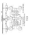
- FIG. 24 shows a constitution of a cell network corresponding to a portion which processes the pre-labeled cell.
- C i denotes an image segmentation cell
- W ij denotes a coupling weight register
- BS i denotes a pre-labeled cell processing circuit.
- Signals b_pre, b_next are input/output signals of token passing for performing the broadcasting described later
- b_label is a broadcast signal to the data bus or a signal of the broadcast label.
- a signal LM is a control signal for forcibly bringing the pre-labeled cell into the ignited state.
- the coupling weight register W ij has the same constitution as that shown in FIG. 8.
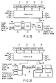
- the image segmentation cell C i concretely has a constitution shown in FIG. 25 or 26.
- the constitutions shown in FIGS. 25, 26 are basically the same as those of FIGS. 7A, 7B. Therefore, in FIGS. 25 and 26, the same parts as those of FIGS. 7A and 7B are denoted with the same reference numerals, and the description is omitted.
- a difference lies in a constitution in which a control circuit 28' shown in FIGS. 25 and 26 forcibly performs the ignition by the signal LM from the pre-labeled cell processing circuit BS i .
- the ignited pre-labeled cell is compared with the label attached to the divided region of the pre-labeled portion of the block previously subjected to the image segmentation, and the pre-labeled cell having the same label needs to be ignited. To effect this, as shown in FIG.
- the pre-labeled cell processing circuit BS i comprises: a previous label register BS-1 in which the label of the segmentation result in the previous image segmentation is stored; a label comparator BS-2 for use in comparing the stored label with the label number or the leader cell being ignited; a pre-label ignition flag register (a value is held data is assumed as B i ) BS-3 for use in the broadcasting; and a control circuit BS-4 which controls input/output of signals of the respective circuits BS-1 to BS-3.
- the label (b_label) stored in the previous label register BS-1 is broadcast to all the other pre-labeled cells through the data bus in order to ignite the cells having the same label in the other pre-labeled cells at the same time. Additionally, when there are a plurality of ignited pre-labeled cells, the respective ignited pre-labeled cells needs to be limited so as not to execute the broadcasting at the same time.
- the pre-labeled cell processing circuit BS i includes the pre-label ignition flag register (Bi) BS-3, and the corresponding pre-labeled cell is regarded as a candidate of a broadcastable cell as long as the value B i held in the register BS-3 is 1.
- data of competitive labels is transferred to the label control circuit 17 shown in FIG. 22 through the data bus in order to store correspondence of the competitive labels during the image segmentation of the region.
- the label control circuit 17 comprises a label control unit 171, a counter 172, a D-latch type flip flop 173, and an AND gate 174.
- the circuit receives pre-label data (pre_labeled) of each block, label number (label i ), and global suppressor Z in synchronization with the clock CLK, and obtains an exception signal and label number in each block to notify the SIA control circuit 18.
- the SIA control circuit 18 shown in FIG. 29 designates a pixel address raddr designated from the outside in the input image memory 11 to read image data I i by a block unit. In this case, the SIA control circuit 18 reads the data in which the boundary portion of the block overlaps by one pixel as shown in FIGS. 17A to 17D.
- the above-described data is sent to the image segmentation cell network 14 to start the image segmentation.
- the end of the ignition operation of the region can be detected by falling of the z signal of the global suppressor circuit to "0" from "1".
- a write signal labelw is set to write the same label number label in the same ignited region.
- the operation of the SIA architecture of the present invention at this time is slightly different from that of the conventional image segmentation architecture, and is roughly divided into the following two cases as shown in FIGS. 30A to 30C:
- the label number is written into the image segmentation memory through an SIA controller.
- the SIA control circuit 18 refers to the address raddr of the requested pixel to read the label number label from the image segmentation memory 15. Additionally, concerning the exceptional label number, the label number SIA_label rewritten in accordance with the table is read.
- the label number is a competitive label
- competition of the label in the image segmentation memory 15 is removed beforehand by post-processing. That is, it is also possible to change the label using the SIA control circuit 18. In this case, it is not necessary to refer to the label table every time there is a request from the upper application.
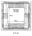
- the image segmentation apparatus having the image segmentation architecture based on the BAO and SIA techniques of the present invention was designed into an integrated circuit using hardware description language Verilog-HDL.
- the prepared Verilog-HDL description was subjected to logic synthesis and automatic placement and routing using a standard cell library of three-metal layer wiring 0.35 ⁇ m CMOS technology to prepare a layout.
- FIG. 31 shows the layout.
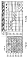
- the power consumption of the proposed architecture was estimated by simulation based on the design result using circuit simulation software (HSPICE). Results are shown in Table 2. The simulation was performed with respect to an input pattern in which the power consumption was maximized. Assuming that a clock frequency is 10 MHz, the power is 6.81 mW, and it was possible to save the power consumption by about 75% as compared with the conventional method. Comparison Result of Power Consumption of proposed BAO Architecture with conventional Architecture (0.35 ⁇ m CMOS technology, 10-MHz clock frequency, HSPICE Simulation) Conventional architecture Architecture of present invention Reduction ratio Average power consumption 24.4 mW at 10 MHz 76.2% Maximum power consumption 30.9 mW at 10 MHz 6.81 mW at 10 MHz 78.0%
- the effectiveness of the SIA technique was verified.
- the SIA is used, even the image having a large size can be processed by pipeline processing while the input image is divided into several blocks.
- the image segmentation is possible at 15 ⁇ sec at 10 MHz on average. Therefore, for example, when the image having the VGA size (640 ⁇ 480 pixels) is considered, as shown in FIG. 16, 33 ⁇ 25 is regarded as one block, the image is divided into 20 ⁇ 20 blocks, and each block is processed by pipeline. Accordingly, the processing is possible at about 9 msec at 10 MHz with an average power consumption of 19.8 mW at 10 MHz and a chip area of 43 mm 2 .
- a small area/low power consumption real-time image segmentation architecture has been proposed using the boundary active only (BAO) scheme and subdivided image approach (SIA).
- BAO boundary active only
- SIA subdivided image approach
- the proposed architecture has a higher speed as compared with the targeted real-time processing, and therefore the SIA for successively performing the processing using the cell network having a small 33 ⁇ 25 pixel size is used. Accordingly, even the large-scaled image having the VGA size can be processed in real time with the low power consumption not only in the most advanced CMOS technology but also in the inexpensively established 0.35 ⁇ m CMOS technology.
- An image segmentation apparatus, an image segmentation method, and an image segmentation integrated circuit according to the present invention are applicable to an image segmentation/extraction integrated circuit for image segmentation/extraction in an image recognition system, mobile object detection system, digital camera, digital video camera, robot vision, authentication system by face recognition, security system, artificial intelligence system and the like.
Landscapes
- Engineering & Computer Science (AREA)
- Physics & Mathematics (AREA)
- General Physics & Mathematics (AREA)
- Theoretical Computer Science (AREA)
- Multimedia (AREA)
- Computer Vision & Pattern Recognition (AREA)
- Software Systems (AREA)
- Image Analysis (AREA)
- Image Processing (AREA)
- Mobile Radio Communication Systems (AREA)
- Ultra Sonic Daignosis Equipment (AREA)
- Compression Or Coding Systems Of Tv Signals (AREA)
Applications Claiming Priority (2)
| Application Number | Priority Date | Filing Date | Title |
|---|---|---|---|
| JP2003322163 | 2003-09-12 | ||
| JP2003322163A JP3955953B2 (ja) | 2003-09-12 | 2003-09-12 | 画像分割処理装置、画像分割処理方法及び画像分割処理集積化回路 |
Publications (2)
| Publication Number | Publication Date |
|---|---|
| EP1515275A2 true EP1515275A2 (de) | 2005-03-16 |
| EP1515275A3 EP1515275A3 (de) | 2010-06-02 |
Family
ID=34132070
Family Applications (1)
| Application Number | Title | Priority Date | Filing Date |
|---|---|---|---|
| EP04019070A Withdrawn EP1515275A3 (de) | 2003-09-12 | 2004-08-11 | Vorrichtung, Verfahren, sowie integrierter Schaltkreis zur Bildsegmentierung |
Country Status (5)
| Country | Link |
|---|---|
| US (2) | US7526127B2 (de) |
| EP (1) | EP1515275A3 (de) |
| JP (1) | JP3955953B2 (de) |
| KR (1) | KR100651340B1 (de) |
| TW (1) | TWI257589B (de) |
Families Citing this family (16)
| Publication number | Priority date | Publication date | Assignee | Title |
|---|---|---|---|---|
| JP4859390B2 (ja) * | 2005-05-10 | 2012-01-25 | 株式会社リコー | 画像処理方法及び画像処理装置 |
| US7817841B2 (en) * | 2005-11-12 | 2010-10-19 | General Electric Company | Time-lapse cell cycle analysis of unstained nuclei |
| US8374454B2 (en) * | 2009-07-28 | 2013-02-12 | Eastman Kodak Company | Detection of objects using range information |
| US8509519B2 (en) * | 2009-07-29 | 2013-08-13 | Intellectual Ventures Fund 83 Llc | Adjusting perspective and disparity in stereoscopic image pairs |
| US8213052B2 (en) * | 2009-07-31 | 2012-07-03 | Eastman Kodak Company | Digital image brightness adjustment using range information |
| US8218823B2 (en) * | 2009-08-11 | 2012-07-10 | Eastman Kodak Company | Determining main objects using range information |
| US8270731B2 (en) * | 2009-08-19 | 2012-09-18 | Eastman Kodak Company | Image classification using range information |
| KR100973964B1 (ko) | 2009-11-13 | 2010-08-05 | 재단법인대구경북과학기술원 | 영역 기반 영상 처리에서 병렬적인 박스 필터링을 수행하는 방법 및 장치 |
| US10205953B2 (en) * | 2012-01-26 | 2019-02-12 | Apple Inc. | Object detection informed encoding |
| US9154130B2 (en) * | 2014-01-14 | 2015-10-06 | Analog Devices, Inc. | Four-state input detection circuitry |
| US10198626B2 (en) * | 2016-10-19 | 2019-02-05 | Snap Inc. | Neural networks for facial modeling |
| TWI629046B (zh) * | 2017-02-10 | 2018-07-11 | 國立勤益科技大學 | 漸進式醫學灰階影像主體分割方法 |
| CN113866620A (zh) * | 2021-09-26 | 2021-12-31 | 国网福建省电力有限公司福州供电公司 | 一种基于无线光电传感的刀闸状态检测装置及方法 |
| CN114037715B (zh) * | 2021-11-09 | 2025-08-26 | 北京字节跳动网络技术有限公司 | 图像分割方法、装置、设备及存储介质 |
| TWI871008B (zh) * | 2022-10-26 | 2025-01-21 | 德商卡爾蔡司Smt有限公司 | 用於半導體檢查圖像分割的改進方法和裝置 |
| US12579668B2 (en) * | 2023-06-14 | 2026-03-17 | Sectra Ab | Viewer systems and related methods with multi-piece registration |
Family Cites Families (6)
| Publication number | Priority date | Publication date | Assignee | Title |
|---|---|---|---|---|
| JP2863072B2 (ja) * | 1993-10-21 | 1999-03-03 | シャープ株式会社 | 画像階調変換方法及び画像処理装置 |
| JPH08167028A (ja) | 1994-12-13 | 1996-06-25 | Toppan Printing Co Ltd | 画像処理方法 |
| JPH11185033A (ja) | 1997-12-22 | 1999-07-09 | Canon Inc | 画像処理方法及び装置 |
| JPH11339041A (ja) | 1998-05-26 | 1999-12-10 | Ricoh Co Ltd | カラー画像処理方法及び装置並びに記録媒体 |
| JP2003044850A (ja) | 2001-07-31 | 2003-02-14 | Takashi Morie | 画像領域抽出方法及び装置 |
| JP3689740B2 (ja) | 2002-05-27 | 2005-08-31 | 国立大学法人広島大学 | 画像分割処理方法、画像分割処理装置、リアルタイム画像処理方法、リアルタイム画像処理装置及び画像処理集積化回路 |
-
2003
- 2003-09-12 JP JP2003322163A patent/JP3955953B2/ja not_active Expired - Lifetime
-
2004
- 2004-08-11 US US10/915,559 patent/US7526127B2/en active Active
- 2004-08-11 EP EP04019070A patent/EP1515275A3/de not_active Withdrawn
- 2004-08-17 TW TW093124680A patent/TWI257589B/zh not_active IP Right Cessation
- 2004-08-18 KR KR1020040065081A patent/KR100651340B1/ko not_active Expired - Fee Related
-
2008
- 2008-04-07 US US12/098,650 patent/US7599557B2/en not_active Expired - Lifetime
Non-Patent Citations (2)
| Title |
|---|
| JIANPING FAN ET AL: "Automatic Image Segmentation by Integrating Color-Edge Extraction and Seeded Region Growing" IEEE TRANSACTIONS ON IMAGE PROCESSING, IEEE SERVICE CENTER, PISCATAWAY, NJ, US, vol. 10, no. 10, 1 October 2001 (2001-10-01), XP011025844 ISSN: 1057-7149 * |
| POHLE R ET AL: "Segmentation of medical images using adaptive region growing" PROCEEDINGS OF THE SPIE, SPIE, US LNKD- DOI:10.1117/12.431013, vol. 4322, 1 January 2001 (2001-01-01), pages 1337-1346, XP002332490 ISSN: 0277-786X * |
Also Published As
| Publication number | Publication date |
|---|---|
| KR100651340B1 (ko) | 2006-11-29 |
| US7599557B2 (en) | 2009-10-06 |
| TWI257589B (en) | 2006-07-01 |
| JP3955953B2 (ja) | 2007-08-08 |
| EP1515275A3 (de) | 2010-06-02 |
| US20080187223A1 (en) | 2008-08-07 |
| TW200517981A (en) | 2005-06-01 |
| KR20050026998A (ko) | 2005-03-17 |
| JP2005092362A (ja) | 2005-04-07 |
| US7526127B2 (en) | 2009-04-28 |
| US20050058345A1 (en) | 2005-03-17 |
Similar Documents
| Publication | Publication Date | Title |
|---|---|---|
| US7599557B2 (en) | Image segmentation apparatus, image segmentation method, and image segmentation integrated circuit for processing an image | |
| US8265350B2 (en) | Method and apparatus for detecting and processing specific pattern from image | |
| EP0666533A1 (de) | Prozessor für ein numerisches Signal | |
| US7298899B2 (en) | Image segmentation method, image segmentation apparatus, image processing method, and image processing apparatus | |
| CN111931720B (zh) | 跟踪图像特征点的方法、装置、计算机设备和存储介质 | |
| CN118570255A (zh) | 运动目标的检测跟踪方法、装置、计算机设备及存储介质 | |
| CN111046746A (zh) | 一种车牌检测方法及装置 | |
| CN112700478A (zh) | 目标跟踪方法、系统、计算机可读存储介质和程序产品 | |
| Park et al. | A vision processor with a unified interest-point detection and matching hardware for accelerating a stereo-matching algorithm | |
| CN119762906A (zh) | 模型训练方法、目标检测方法、装置、设备、介质及产品 | |
| Zhang et al. | Bucket-FEM: A bucket-based architecture of real-time ORB feature extraction and matching for embedded SLAM applications | |
| Zho et al. | A RMB optical character recognition system using FPGA | |
| CN114898092B (zh) | 一种用于空间目标同步检测与分割的方法 | |
| US11800258B2 (en) | High-performance CNN inference model at the pixel-parallel CMOS image sensor | |
| JP2007228156A (ja) | 動き検出処理装置および方法 | |
| CN120495155B (zh) | 图像的检测方法、装置、设备、可读介质 | |
| CN117237697B (zh) | 一种小样本图像检测方法、系统、介质及设备 | |
| CN119380029B (zh) | 伪标签生成及无源域场景自适应的遮挡感知无缝分割方法及系统 | |
| CN120013744B (zh) | 基于fpga实现快速聚类目标检测方法、装置、设备和介质 | |
| CN114881859B (zh) | Ic逆向工程中的图像拼接方法及系统 | |
| Chen et al. | PCR-ORB: Enhanced ORB-SLAM3 with Point Cloud Refinement Using Deep Learning-Based Dynamic Object Filtering | |
| CN121937729A (zh) | 基于深度学习的道路裂缝分割方法、装置、电子设备及程序产品 | |
| Tang | Development of a New Tracking System based on CMOS Vision Processor Hardware: Phase I | |
| Wang et al. | A Visual SLAM System in Dynamic Environments Based on YOLO11 Instance Segmentation | |
| Taranco Serna et al. | Sliding window support for image processing in autonomous vehicles |
Legal Events
| Date | Code | Title | Description |
|---|---|---|---|
| PUAI | Public reference made under article 153(3) epc to a published international application that has entered the european phase |
Free format text: ORIGINAL CODE: 0009012 |
|
| 17P | Request for examination filed |
Effective date: 20040811 |
|
| AK | Designated contracting states |
Kind code of ref document: A2 Designated state(s): AT BE BG CH CY CZ DE DK EE ES FI FR GB GR HU IE IT LI LU MC NL PL PT RO SE SI SK TR |
|
| AX | Request for extension of the european patent |
Extension state: AL HR LT LV MK |
|
| PUAL | Search report despatched |
Free format text: ORIGINAL CODE: 0009013 |
|
| AK | Designated contracting states |
Kind code of ref document: A3 Designated state(s): AT BE BG CH CY CZ DE DK EE ES FI FR GB GR HU IE IT LI LU MC NL PL PT RO SE SI SK TR |
|
| AX | Request for extension of the european patent |
Extension state: AL HR LT LV MK |
|
| AKX | Designation fees paid |
Designated state(s): DE FR GB IT |
|
| STAA | Information on the status of an ep patent application or granted ep patent |
Free format text: STATUS: THE APPLICATION HAS BEEN WITHDRAWN |
|
| 18W | Application withdrawn |
Effective date: 20120629 |