EP1515210A2 - Robotersystem und Steuerverfahren hierzu - Google Patents
Robotersystem und Steuerverfahren hierzu Download PDFInfo
- Publication number
- EP1515210A2 EP1515210A2 EP04250986A EP04250986A EP1515210A2 EP 1515210 A2 EP1515210 A2 EP 1515210A2 EP 04250986 A EP04250986 A EP 04250986A EP 04250986 A EP04250986 A EP 04250986A EP 1515210 A2 EP1515210 A2 EP 1515210A2
- Authority
- EP
- European Patent Office
- Prior art keywords
- reflecting
- command
- light
- mobile robot
- trace
- Prior art date
- Legal status (The legal status is an assumption and is not a legal conclusion. Google has not performed a legal analysis and makes no representation as to the accuracy of the status listed.)
- Withdrawn
Links
Images


Classifications
-
- G—PHYSICS
- G05—CONTROLLING; REGULATING
- G05D—SYSTEMS FOR CONTROLLING OR REGULATING NON-ELECTRIC VARIABLES
- G05D1/00—Control of position, course, altitude or attitude of land, water, air or space vehicles, e.g. using automatic pilots
- G05D1/02—Control of position or course in two dimensions
- G05D1/021—Control of position or course in two dimensions specially adapted to land vehicles
- G05D1/0212—Control of position or course in two dimensions specially adapted to land vehicles with means for defining a desired trajectory
- G05D1/0221—Control of position or course in two dimensions specially adapted to land vehicles with means for defining a desired trajectory involving a learning process
-
- G—PHYSICS
- G05—CONTROLLING; REGULATING
- G05D—SYSTEMS FOR CONTROLLING OR REGULATING NON-ELECTRIC VARIABLES
- G05D1/00—Control of position, course, altitude or attitude of land, water, air or space vehicles, e.g. using automatic pilots
- G05D1/20—Control system inputs
- G05D1/24—Arrangements for determining position or orientation
- G05D1/242—Means based on the reflection of waves generated by the vehicle
-
- B—PERFORMING OPERATIONS; TRANSPORTING
- B25—HAND TOOLS; PORTABLE POWER-DRIVEN TOOLS; MANIPULATORS
- B25J—MANIPULATORS; CHAMBERS PROVIDED WITH MANIPULATION DEVICES
- B25J9/00—Program-controlled manipulators
- B25J9/10—Program-controlled manipulators characterised by positioning means for manipulator elements
-
- A—HUMAN NECESSITIES
- A47—FURNITURE; DOMESTIC ARTICLES OR APPLIANCES; COFFEE MILLS; SPICE MILLS; SUCTION CLEANERS IN GENERAL
- A47L—DOMESTIC WASHING OR CLEANING; SUCTION CLEANERS IN GENERAL
- A47L9/00—Details or accessories of suction cleaners, e.g. mechanical means for controlling the suction or for effecting pulsating action; Storing devices specially adapted to suction cleaners or parts thereof; Carrying-vehicles specially adapted for suction cleaners
- A47L9/28—Installation of the electric equipment, e.g. adaptation or attachment to the suction cleaner; Controlling suction cleaners by electric means
- A47L9/2805—Parameters or conditions being sensed
-
- A—HUMAN NECESSITIES
- A47—FURNITURE; DOMESTIC ARTICLES OR APPLIANCES; COFFEE MILLS; SPICE MILLS; SUCTION CLEANERS IN GENERAL
- A47L—DOMESTIC WASHING OR CLEANING; SUCTION CLEANERS IN GENERAL
- A47L9/00—Details or accessories of suction cleaners, e.g. mechanical means for controlling the suction or for effecting pulsating action; Storing devices specially adapted to suction cleaners or parts thereof; Carrying-vehicles specially adapted for suction cleaners
- A47L9/28—Installation of the electric equipment, e.g. adaptation or attachment to the suction cleaner; Controlling suction cleaners by electric means
- A47L9/2836—Installation of the electric equipment, e.g. adaptation or attachment to the suction cleaner; Controlling suction cleaners by electric means characterised by the parts which are controlled
- A47L9/2852—Elements for displacement of the vacuum cleaner or the accessories therefor, e.g. wheels, casters or nozzles
-
- A—HUMAN NECESSITIES
- A47—FURNITURE; DOMESTIC ARTICLES OR APPLIANCES; COFFEE MILLS; SPICE MILLS; SUCTION CLEANERS IN GENERAL
- A47L—DOMESTIC WASHING OR CLEANING; SUCTION CLEANERS IN GENERAL
- A47L9/00—Details or accessories of suction cleaners, e.g. mechanical means for controlling the suction or for effecting pulsating action; Storing devices specially adapted to suction cleaners or parts thereof; Carrying-vehicles specially adapted for suction cleaners
- A47L9/28—Installation of the electric equipment, e.g. adaptation or attachment to the suction cleaner; Controlling suction cleaners by electric means
- A47L9/2857—User input or output elements for control, e.g. buttons, switches or displays
-
- G—PHYSICS
- G05—CONTROLLING; REGULATING
- G05D—SYSTEMS FOR CONTROLLING OR REGULATING NON-ELECTRIC VARIABLES
- G05D1/00—Control of position, course, altitude or attitude of land, water, air or space vehicles, e.g. using automatic pilots
- G05D1/0011—Control of position, course, altitude or attitude of land, water, air or space vehicles, e.g. using automatic pilots associated with a remote control arrangement
- G05D1/0016—Control of position, course, altitude or attitude of land, water, air or space vehicles, e.g. using automatic pilots associated with a remote control arrangement characterised by the operator's input device
-
- G—PHYSICS
- G05—CONTROLLING; REGULATING
- G05D—SYSTEMS FOR CONTROLLING OR REGULATING NON-ELECTRIC VARIABLES
- G05D1/00—Control of position, course, altitude or attitude of land, water, air or space vehicles, e.g. using automatic pilots
- G05D1/0011—Control of position, course, altitude or attitude of land, water, air or space vehicles, e.g. using automatic pilots associated with a remote control arrangement
- G05D1/0033—Control of position, course, altitude or attitude of land, water, air or space vehicles, e.g. using automatic pilots associated with a remote control arrangement by having the operator tracking the vehicle either by direct line of sight or via one or more cameras located remotely from the vehicle
-
- G—PHYSICS
- G05—CONTROLLING; REGULATING
- G05D—SYSTEMS FOR CONTROLLING OR REGULATING NON-ELECTRIC VARIABLES
- G05D1/00—Control of position, course, altitude or attitude of land, water, air or space vehicles, e.g. using automatic pilots
- G05D1/20—Control system inputs
- G05D1/22—Command input arrangements
- G05D1/221—Remote-control arrangements
- G05D1/222—Remote-control arrangements operated by humans
-
- A—HUMAN NECESSITIES
- A47—FURNITURE; DOMESTIC ARTICLES OR APPLIANCES; COFFEE MILLS; SPICE MILLS; SUCTION CLEANERS IN GENERAL
- A47L—DOMESTIC WASHING OR CLEANING; SUCTION CLEANERS IN GENERAL
- A47L2201/00—Robotic cleaning machines, i.e. with automatic control of the travelling movement or the cleaning operation
- A47L2201/04—Automatic control of the travelling movement; Automatic obstacle detection
Definitions
- the present invention relates to a robot system and a control method thereof, and more particularly, to a robot system and a control method thereof, in which a light generator is used to command or teach a mobile robot.
- Figure 1 is a block diagram of a teaching pendent system to describe a conventional teaching pendent method.
- the teaching pendent system includes a teaching pendent 100, a mobile robot 110, a controller 120, and a memory 130.
- the teaching pendent 100 receives information on a moving path, etc. for a mobile robot 110 inputted by an operator through a keyboard, and transmits the information to the controller 120.
- the controller 120 controls the mobile robot 110 to operate according to the received information, and stores the operation in the memory 130.
- An operator makes a detailed plan for a partial moving path and the operation for the mobile robot 110 from a robot's point of view, and then controls the mobile robot 110 to move by using buttons provided in the teaching pendent 100.
- the operator stores performed serial operations and its respective positions in the memory 130. Then, the operator repeatedly performs making the plan for the operation, controlling the mobile robot 110, and storing the operation until the operation related to a whole moving path is stored. Then, the stored operation of the mobile robot 110 is tested. In the case where the test result is in accordance with the plan made by the operator, the mobile robot 110 will be used, and is controlled based on the stored operation.
- teaching pendent 100 necessary operations of the mobile robot 110 are repeatedly inputted by a remote controller called the teaching pendent 100 and then practically tested in every case.
- teaching pendent 100 a remote controller
- off-line program method detailed operations are programmed by an operator with a graphic or a text, and then tested through simulation, thereby applying the programmed operations to the mobile robot.
- an operator makes a plan for the operations for the mobile robot from the robot's view, and programs serial operations and its respective positions for the mobile robot with the graphic or the text.
- the programmed operations are displayed into the simulations, so that the operator makes crosschecks between the simulations and the plan.
- the operator modifies the plan and repeats the simulation until the plan is in accordance with the simulation.
- simulation information is uploaded to the controller of the mobile robot, and then practically tested in the mobile robot.
- the off-line program method requires an expensive computer system and an expensive program. Further, the compensating process is needed to compensate the difference between the ideal position based on the simulation and the practical position. Thus, the off-line program method becomes complicated, and it is difficult to immediately teach the mobile robot.
- An aim of the present invention is to provide an inexpensive robot system and a control method thereof, in which immediate operation teaching is possible and a user may easily operate a robot.
- a robot system including a mobile robot with a driving part to move.
- the robot system includes a light commander to emit light and give a command to correspond to a reflecting position at which the light is reflected.
- the robot system also includes a position detector to receive information on the reflecting position as an image, and to detect the reflecting position.
- the robot system includes a controller to determine a reflecting trace based on a plurality of reflecting positions detected by the position detector, and to output the reflecting trace to the driving part to control the driving part.
- the robot system further includes a memory to store commands, and command patterns formed by the reflecting positions which correspond to the commands.
- the controller determines whether the reflecting trace based on the reflecting positions is in accordance with the command patterns corresponding to the commands stored in the memory, and outputs the command to the driving part when the reflecting trace is in accordance with the command patterns.
- the light commander includes a laser pointer to point at a point in a three dimensional space by using a laser beam.
- the position detector includes an optical device to detect the reflecting position at which the light emitted from the light commander is reflected.
- a method of controlling a robot system including a mobile robot with a driving part to move.
- the method includes providing a light commander to emit light and give commands to correspond to a reflecting position at which the light is reflected.
- the method also includes providing a memory to store the command, and command pattern formed by the reflecting position which corresponds to the commands, and detecting the reflecting positions by the light from the light commander at a predetermined time interval.
- the method includes determining a reflecting trace based on the reflecting position when an interval change between a first and second reflecting position is within a predetermined interval, determining whether the reflecting trace is in accordance with the command patterns, and controlling the mobile robot to operate according to the commands corresponding to the command patterns when the reflecting trace is in accordance with the command patterns.
- the mobile robot when the reflecting trace is not in accordance with the command patterns and draws a line segment, the mobile robot is controlled to move along the line segment.
- the mobile robot when the reflecting trace is not in accordance with the command patterns and draws a closed loop, the mobile robot is controlled to enter an area formed by the closed loop.
- the mobile robot when the reflecting trace is not in accordance with the command pattern and points to a point, the mobile robot is controlled to move to the point.
- a plurality of reflecting traces corresponding to several controls are stored as one command pattern in the memory.
- FIG. 2 is a block diagram of a robot system, according to an embodiment of the present invention.
- a robot system includes a driving part 10, a light commander 20, a position detector 30, a memory 40, and a controller 50.
- the driving part 10 is provided in a mobile robot, and includes mechanical components to drive the mobile robot to move.
- the driving part 10 receives commands on direction and speed for the mobile robot from a controller 50.
- the light commander 20 emits light and gives a command for the mobile robot which corresponds to a reflecting position at which the light is reflected. That is, an operator inputs a target position, a moving trace, and a command pattern of the mobile robot through the light commander 20.
- any light may be used as the light, which travels in a straight line and is reflected so as to be input to the position detector 30 of the mobile robot.
- the position detector 30 detects a teaching position by receiving information on the reflecting position at which the light emitted from the light commander 20 is reflected, and outputs it to the controller 50.
- the position detector 30 includes a position receiving part to receive the information of the teaching position (that is, the reflecting position taught by the light commander 20), and the position receiving part may vary according to a characteristic of the light used for the light commander 20. For example, when a laser beam is used as the light, an optical device may be used as the position receiving part. Thus, the optical device receives the information on the reflecting position as an image, and calculates coordinates of the teaching position relative to the mobile robot through a predetermined processor, thereby outputting the coordinates to the controller 50.
- the controller 50 determines a reflecting trace drawn through the coordinates of the reflecting positions detected by the position detector 30, and transmits the reflecting trace to the driving part 10, thereby controlling the driving part 10.
- the memory 40 previously stores the commands and command patterns formed by the reflecting positions which correspond to the commands.
- the controller 50 determines whether the reflecting trace based on the reflecting positions detected by the position detector 30 is in accordance with a command pattern corresponding to the commands stored in the memory 40. When the reflecting trace is in accordance with the command pattern, the controller 50 transmits a command corresponding to the command pattern to the driving part 10, thereby controlling the driving part 10.
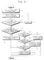
- Figure 3 is a control flowchart of the robot system of Figure 2.
- an operator creates the teaching position by pointing at a predetermined position through a laser pointer used as the light commander 20.
- the optical device mounted in the mobile robot receives the teaching position taught by the light commander 20 as an image, and calculates the coordinates of the teaching position relative to the mobile robot with an image processor.
- the controller 50 compares the coordinates of a present teaching position detected by the position detector 30 with coordinates of a former teaching position, and determines whether or not there is a predetermined interval between the present teaching position and the former teaching position.
- the controller 50 first determines the reflecting trace drawn via the teaching positions and then determines whether or not the reflecting trace is in accordance with a command pattern previously stored in the memory 40.
- the controller 50 gives a command to correspond to the command pattern.
- Figure 4 illustrates a reflecting trace in accordance with a command pattern.
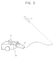
- a mobile robot 60 includes a driving part 10, an optical device 31, and a cleaner 61.
- the driving part 10 includes mechanical components such as a motor, a motor driving circuit, a driving shaft, and wheels to move the mobile robot 60.
- the optical device 31 receives teaching position pointed by a laser pointer 21 as an image.
- the cleaner 61 performs cleaning along a specified moving path.
- the mobile robot 60 and the laser pointer 21 shown in Figure 4 are identical to those in Figures 5 and 6, so that repetitive descriptions thereof are omitted.
- the controller 50 controls the driving part 10 to drive the mobile robot 60 to move forward in the straight line. At this time, the mobile robot 60 may clean while moving.
- the mobile robot 60 is controlled according to the commands based on patterns of the reflecting trace.
- the controller 50 controls the driving part 10 to drive the mobile robot 60 to move along the line segment.
- Figure 5 illustrates that the reflecting trace draws the line segment. Particularly, when the reflecting trace draws an "S"-shaped curve, the controller 50 controls the mobile robot 60 to move along the "S"-shaped curve. When the reflecting trace draws the closed loop, at operation S11, the controller 50 controls the driving part 10 to drive the mobile robot 60 to enter an area formed by the closed loop.
- Figure 6 illustrates that the reflecting trace draws the closed loop.
- the controller 50 controls the mobile robot 60 to enter the specified area and to clean the area.
- the controller 50 controls the driving part 10 to drive the mobile robot 60 to move to the point.
- the controller 50 may give one command by combining the several patterns of the reflecting traces, and store the pattern combination as the coordinates, thereby controlling the mobile robot 60.
- the present invention provides a robot system and a control method thereof, in which cost reduction, and easy and safe operation are provided. Thus, immediate operation teaching is possible without a compensating process.
Landscapes
- Engineering & Computer Science (AREA)
- Physics & Mathematics (AREA)
- Automation & Control Theory (AREA)
- Radar, Positioning & Navigation (AREA)
- Remote Sensing (AREA)
- Aviation & Aerospace Engineering (AREA)
- General Physics & Mathematics (AREA)
- Mechanical Engineering (AREA)
- Theoretical Computer Science (AREA)
- Computing Systems (AREA)
- Mathematical Physics (AREA)
- Robotics (AREA)
- Numerical Control (AREA)
- Manipulator (AREA)
- Control Of Position, Course, Altitude, Or Attitude Of Moving Bodies (AREA)
- Electric Vacuum Cleaner (AREA)
Applications Claiming Priority (2)
| Application Number | Priority Date | Filing Date | Title |
|---|---|---|---|
| KR2003053377 | 2003-08-01 | ||
| KR10-2003-0053377A KR100520079B1 (ko) | 2003-08-01 | 2003-08-01 | 로봇시스템 및 그 제어방법 |
Publications (2)
| Publication Number | Publication Date |
|---|---|
| EP1515210A2 true EP1515210A2 (de) | 2005-03-16 |
| EP1515210A3 EP1515210A3 (de) | 2005-11-30 |
Family
ID=34101812
Family Applications (1)
| Application Number | Title | Priority Date | Filing Date |
|---|---|---|---|
| EP04250986A Withdrawn EP1515210A3 (de) | 2003-08-01 | 2004-02-24 | Robotersystem und Steuerverfahren hierzu |
Country Status (5)
| Country | Link |
|---|---|
| US (1) | US20050027399A1 (de) |
| EP (1) | EP1515210A3 (de) |
| JP (1) | JP4002250B2 (de) |
| KR (1) | KR100520079B1 (de) |
| CN (1) | CN100349079C (de) |
Cited By (3)
| Publication number | Priority date | Publication date | Assignee | Title |
|---|---|---|---|---|
| DE102016210422A1 (de) * | 2016-06-13 | 2017-12-14 | BSH Hausgeräte GmbH | Teach-In Vorrichtung und Verfahren zum Steuern eines Reinigungsroboters |
| DE102016210421A1 (de) * | 2016-06-13 | 2017-12-14 | BSH Hausgeräte GmbH | Verfahren zum Steuern eines Reinigungsroboters |
| DE102020209608C5 (de) | 2020-07-30 | 2025-07-24 | BSH Hausgeräte GmbH | Bodenreinigungssystem |
Families Citing this family (23)
| Publication number | Priority date | Publication date | Assignee | Title |
|---|---|---|---|---|
| DE10361018C9 (de) * | 2003-12-23 | 2021-03-04 | QUISS Qualitäts-Inspektionssysteme und Service GmbH | Verfahren zum Erkennen einer auf einem Substrat aufzubringenden Struktur mit mehreren Kameras sowie eine Vorrichtung hierfür |
| KR101293247B1 (ko) * | 2006-02-07 | 2013-08-09 | 삼성전자주식회사 | 자율 이동 로봇 및 그 제어 방법 |
| JP5046053B2 (ja) * | 2009-02-09 | 2012-10-10 | 独立行政法人科学技術振興機構 | ロボット制御システム及びロボット制御方法 |
| TWI555496B (zh) * | 2011-05-17 | 2016-11-01 | 微星科技股份有限公司 | 清潔系統及其控制方法 |
| DE102011053386A1 (de) * | 2011-06-28 | 2013-01-03 | Vorwerk & Co. Interholding Gmbh | Selbsttätig verfahrbares Gerät sowie Verfahren zur Zielführung eines solchen Gerätes |
| JP6022394B2 (ja) * | 2013-03-28 | 2016-11-09 | 株式会社神戸製鋼所 | 作業経路情報設定装置、プログラム、および作業経路情報設定方法 |
| WO2015090402A1 (en) * | 2013-12-19 | 2015-06-25 | Aktiebolaget Electrolux | Robotic cleaning device with perimeter recording function |
| CN104750105A (zh) * | 2013-12-27 | 2015-07-01 | 科沃斯机器人科技(苏州)有限公司 | 自移动机器人的行走探测控制方法 |
| KR102586010B1 (ko) * | 2014-02-28 | 2023-10-11 | 삼성전자주식회사 | 청소 로봇 및 그에 포함되는 원격 제어기 |
| KR101561921B1 (ko) * | 2014-05-20 | 2015-10-20 | 엘지전자 주식회사 | 청소기 |
| KR102293615B1 (ko) * | 2014-07-02 | 2021-08-26 | 삼성전자주식회사 | 청소 로봇 및 그 제어 방법 |
| CN104089576A (zh) * | 2014-07-09 | 2014-10-08 | 合肥奥博特自动化设备有限公司 | 一种码垛机器人磨损和变形检测方法 |
| CN105446350B (zh) * | 2014-09-26 | 2018-05-29 | 科沃斯机器人股份有限公司 | 自移动机器人移动界限划定方法 |
| KR101620427B1 (ko) | 2014-10-14 | 2016-05-12 | 엘지전자 주식회사 | 로봇 청소기의 제어방법 |
| US20190055017A1 (en) * | 2016-03-02 | 2019-02-21 | Nec Corporation | Unmanned aircraft, unmanned aircraft control system, and flight control method |
| CN107198499B (zh) * | 2016-03-18 | 2021-03-05 | 松下电器(美国)知识产权公司 | 自主移动装置、自主移动方法以及自主移动系统 |
| JP6618087B1 (ja) * | 2018-07-20 | 2019-12-11 | 三菱ロジスネクスト株式会社 | 無人飛行体および無人搬送システム |
| JP6684532B2 (ja) * | 2018-08-27 | 2020-04-22 | 三菱ロジスネクスト株式会社 | 無人飛行体を用いた無人搬送システム |
| JP6877071B2 (ja) * | 2019-08-02 | 2021-05-26 | 三菱ロジスネクスト株式会社 | 無人飛行体および無人搬送システム |
| JP7047830B2 (ja) | 2019-12-05 | 2022-04-05 | オムロン株式会社 | 自律走行システム、自律走行方法、及び自律走行プログラム |
| CN111290378B (zh) * | 2020-01-16 | 2022-05-10 | 宁德师范学院 | 一种移动机器人及其响应控制方法、存储介质 |
| CN114515124B (zh) * | 2022-04-21 | 2022-07-22 | 深圳市倍思科技有限公司 | 清洁位置确定方法、装置、设备及存储介质 |
| EP4533196B1 (de) * | 2022-05-24 | 2025-09-17 | International Business Machines Corporation | Visuelle lichtbasierte richtung zu einem robotersystem |
Family Cites Families (13)
| Publication number | Priority date | Publication date | Assignee | Title |
|---|---|---|---|---|
| US5148573A (en) * | 1991-09-04 | 1992-09-22 | Killian Mark A | Apparatus for attaching a cleaning tool to a robotic manipulator |
| US5809099A (en) * | 1997-05-05 | 1998-09-15 | Korea Atomic Energy Research Institute | Laser-guided underwater wall climbing robot for reactor pressure vessel inspection |
| US6532404B2 (en) * | 1997-11-27 | 2003-03-11 | Colens Andre | Mobile robots and their control system |
| US6304050B1 (en) * | 1999-07-19 | 2001-10-16 | Steven B. Skaar | Means and method of robot control relative to an arbitrary surface using camera-space manipulation |
| US6459955B1 (en) * | 1999-11-18 | 2002-10-01 | The Procter & Gamble Company | Home cleaning robot |
| US6629028B2 (en) * | 2000-06-29 | 2003-09-30 | Riken | Method and system of optical guidance of mobile body |
| JP2002041144A (ja) * | 2000-07-28 | 2002-02-08 | Matsushita Electric Ind Co Ltd | 移動作業ロボット |
| KR100642072B1 (ko) * | 2000-11-22 | 2006-11-10 | 삼성광주전자 주식회사 | 알에프모듈을 이용한 모빌로봇 시스템 |
| SE0100924D0 (sv) * | 2001-03-15 | 2001-03-15 | Electrolux Ab | Energy-efficient navigation of an autonomous surface treatment apparatus |
| RU2220643C2 (ru) * | 2001-04-18 | 2004-01-10 | Самсунг Гванджу Электроникс Ко., Лтд. | Автоматическое чистящее устройство, автоматическая чистящая система и способ управления этой системой (варианты) |
| DE10215167C1 (de) * | 2002-04-05 | 2003-06-18 | Daimler Chrysler Ag | Anordnung und Laserpointer zur Kommandierung eines semiautonomen Systems |
| WO2004016400A2 (en) * | 2002-08-16 | 2004-02-26 | Evolution Robotics, Inc. | Systems and methods for the automated sensing of motion in a mobile robot using visual data |
| JP3841220B2 (ja) * | 2004-01-30 | 2006-11-01 | 船井電機株式会社 | 自律走行ロボットクリーナー |
-
2003
- 2003-08-01 KR KR10-2003-0053377A patent/KR100520079B1/ko not_active Expired - Fee Related
-
2004
- 2004-02-12 CN CNB2004100048859A patent/CN100349079C/zh not_active Expired - Fee Related
- 2004-02-24 EP EP04250986A patent/EP1515210A3/de not_active Withdrawn
- 2004-03-29 JP JP2004096940A patent/JP4002250B2/ja not_active Expired - Fee Related
- 2004-04-08 US US10/820,037 patent/US20050027399A1/en not_active Abandoned
Cited By (5)
| Publication number | Priority date | Publication date | Assignee | Title |
|---|---|---|---|---|
| DE102016210422A1 (de) * | 2016-06-13 | 2017-12-14 | BSH Hausgeräte GmbH | Teach-In Vorrichtung und Verfahren zum Steuern eines Reinigungsroboters |
| DE102016210421A1 (de) * | 2016-06-13 | 2017-12-14 | BSH Hausgeräte GmbH | Verfahren zum Steuern eines Reinigungsroboters |
| EP3258335A1 (de) | 2016-06-13 | 2017-12-20 | BSH Hausgeräte GmbH | Teach-in vorrichtung und verfahren zum steuern eines reinigungsroboters |
| DE102016210422B4 (de) | 2016-06-13 | 2019-08-08 | BSH Hausgeräte GmbH | Teach-In Vorrichtung und Verfahren zum Steuern eines Reinigungsroboters |
| DE102020209608C5 (de) | 2020-07-30 | 2025-07-24 | BSH Hausgeräte GmbH | Bodenreinigungssystem |
Also Published As
| Publication number | Publication date |
|---|---|
| KR100520079B1 (ko) | 2005-10-12 |
| EP1515210A3 (de) | 2005-11-30 |
| US20050027399A1 (en) | 2005-02-03 |
| CN100349079C (zh) | 2007-11-14 |
| KR20050014953A (ko) | 2005-02-21 |
| CN1579714A (zh) | 2005-02-16 |
| JP4002250B2 (ja) | 2007-10-31 |
| JP2005052961A (ja) | 2005-03-03 |
Similar Documents
| Publication | Publication Date | Title |
|---|---|---|
| EP1515210A2 (de) | Robotersystem und Steuerverfahren hierzu | |
| US11534912B2 (en) | Vibration display device, operation program creating device, and system | |
| US5987591A (en) | Multiple-sensor robot system for obtaining two-dimensional image and three-dimensional position information | |
| AU2008249146B2 (en) | Surveying system | |
| JP4441409B2 (ja) | ロボットシミュレーション装置、および、シミュレーションプログラム | |
| JP2003150219A (ja) | 作業機械のシミュレーション装置 | |
| US12077414B2 (en) | Work support device and work support method | |
| US7324907B2 (en) | Self-calibrating sensor orienting system | |
| JP2007090481A (ja) | ロボットシミュレーション装置 | |
| US20240066701A1 (en) | Simulation device using three-dimensional position information obtained from output from vision sensor | |
| WO2022181643A1 (ja) | レーザ加工装置の動作を教示するための教示装置、及び教示方法 | |
| WO2022181688A1 (ja) | ロボットの設置位置測定装置、設置位置測定方法、ロボット制御装置、教示システムおよびシミュレーション装置 | |
| CN106959762B (zh) | 虚拟现实系统及方法 | |
| US20250332719A1 (en) | Robot system and modeling method | |
| US8185233B2 (en) | Numerical controller having multi-path control function | |
| CN118715492A (zh) | 示教辅助装置、作业系统、示教辅助方法及示教辅助程序 | |
| JP2021186946A (ja) | センサの検出条件設定方法、検出条件設定プログラムおよび前記プログラムを格納する記録媒体 | |
| Amin-Nejad et al. | A visual servoing system for edge trimming of fabric embroideries by laser | |
| EP1804149B1 (de) | Mobiler Roboter | |
| JP2018124722A (ja) | 制御装置 | |
| JP2008224497A (ja) | 計測位置表示方法および計測装置 | |
| CN119328773B (zh) | 基于强化学习的机器人位置规划方法及装置 | |
| US20070103463A1 (en) | Simulation apparatus | |
| JPH11281327A (ja) | 線幅測定方法及び装置 | |
| CN112034783B (zh) | 机床控制装置以及机床 |
Legal Events
| Date | Code | Title | Description |
|---|---|---|---|
| PUAI | Public reference made under article 153(3) epc to a published international application that has entered the european phase |
Free format text: ORIGINAL CODE: 0009012 |
|
| 17P | Request for examination filed |
Effective date: 20040315 |
|
| AK | Designated contracting states |
Kind code of ref document: A2 Designated state(s): AT BE BG CH CY CZ DE DK EE ES FI FR GB GR HU IE IT LI LU MC NL PT RO SE SI SK TR |
|
| AX | Request for extension of the european patent |
Extension state: AL HR LT LV MK |
|
| PUAL | Search report despatched |
Free format text: ORIGINAL CODE: 0009013 |
|
| AK | Designated contracting states |
Kind code of ref document: A3 Designated state(s): AT BE BG CH CY CZ DE DK EE ES FI FR GB GR HU IE IT LI LU MC NL PT RO SE SI SK TR |
|
| AX | Request for extension of the european patent |
Extension state: AL LT LV MK |
|
| AKX | Designation fees paid |
Designated state(s): DE FR GB |
|
| RAP1 | Party data changed (applicant data changed or rights of an application transferred) |
Owner name: SAMSUNG ELECTRONICS CO., LTD. |
|
| GRAP | Despatch of communication of intention to grant a patent |
Free format text: ORIGINAL CODE: EPIDOSNIGR1 |
|
| INTG | Intention to grant announced |
Effective date: 20150717 |
|
| STAA | Information on the status of an ep patent application or granted ep patent |
Free format text: STATUS: THE APPLICATION IS DEEMED TO BE WITHDRAWN |
|
| 18D | Application deemed to be withdrawn |
Effective date: 20151128 |