EP1515149A2 - Système de blindage magnétique - Google Patents
Système de blindage magnétique Download PDFInfo
- Publication number
- EP1515149A2 EP1515149A2 EP04021139A EP04021139A EP1515149A2 EP 1515149 A2 EP1515149 A2 EP 1515149A2 EP 04021139 A EP04021139 A EP 04021139A EP 04021139 A EP04021139 A EP 04021139A EP 1515149 A2 EP1515149 A2 EP 1515149A2
- Authority
- EP
- European Patent Office
- Prior art keywords
- magnetic
- shielding system
- coil
- ribbon
- field
- Prior art date
- Legal status (The legal status is an assumption and is not a legal conclusion. Google has not performed a legal analysis and makes no representation as to the accuracy of the status listed.)
- Withdrawn
Links
- 238000004804 winding Methods 0.000 claims abstract description 13
- 230000005415 magnetization Effects 0.000 claims abstract description 10
- 239000000696 magnetic material Substances 0.000 claims description 10
- 239000000463 material Substances 0.000 claims description 5
- 230000000694 effects Effects 0.000 description 10
- 230000004907 flux Effects 0.000 description 5
- 229910000697 metglas Inorganic materials 0.000 description 3
- 230000035699 permeability Effects 0.000 description 3
- 229920002430 Fibre-reinforced plastic Polymers 0.000 description 2
- 238000010894 electron beam technology Methods 0.000 description 2
- 239000011151 fibre-reinforced plastic Substances 0.000 description 2
- 238000002582 magnetoencephalography Methods 0.000 description 2
- 238000004519 manufacturing process Methods 0.000 description 2
- 229920005989 resin Polymers 0.000 description 2
- 239000011347 resin Substances 0.000 description 2
- 229920000049 Carbon (fiber) Polymers 0.000 description 1
- 229910045601 alloy Inorganic materials 0.000 description 1
- 239000000956 alloy Substances 0.000 description 1
- 229910000808 amorphous metal alloy Inorganic materials 0.000 description 1
- 239000004917 carbon fiber Substances 0.000 description 1
- 229910017052 cobalt Inorganic materials 0.000 description 1
- 239000010941 cobalt Substances 0.000 description 1
- GUTLYIVDDKVIGB-UHFFFAOYSA-N cobalt atom Chemical compound [Co] GUTLYIVDDKVIGB-UHFFFAOYSA-N 0.000 description 1
- 230000007423 decrease Effects 0.000 description 1
- 230000005389 magnetism Effects 0.000 description 1
- 238000005259 measurement Methods 0.000 description 1
- 239000002184 metal Substances 0.000 description 1
- 229910052751 metal Inorganic materials 0.000 description 1
- VNWKTOKETHGBQD-UHFFFAOYSA-N methane Chemical compound C VNWKTOKETHGBQD-UHFFFAOYSA-N 0.000 description 1
- 239000000123 paper Substances 0.000 description 1
- 238000005096 rolling process Methods 0.000 description 1
Images


Classifications
-
- G—PHYSICS
- G01—MEASURING; TESTING
- G01R—MEASURING ELECTRIC VARIABLES; MEASURING MAGNETIC VARIABLES
- G01R33/00—Arrangements or instruments for measuring magnetic variables
- G01R33/02—Measuring direction or magnitude of magnetic fields or magnetic flux
- G01R33/025—Compensating stray fields
-
- H—ELECTRICITY
- H01—ELECTRIC ELEMENTS
- H01F—MAGNETS; INDUCTANCES; TRANSFORMERS; SELECTION OF MATERIALS FOR THEIR MAGNETIC PROPERTIES
- H01F27/00—Details of transformers or inductances, in general
- H01F27/34—Special means for preventing or reducing unwanted electric or magnetic effects, e.g. no-load losses, reactive currents, harmonics, oscillations, leakage fields
- H01F27/36—Electric or magnetic shields or screens
- H01F27/366—Electric or magnetic shields or screens made of ferromagnetic material
-
- G—PHYSICS
- G01—MEASURING; TESTING
- G01R—MEASURING ELECTRIC VARIABLES; MEASURING MAGNETIC VARIABLES
- G01R33/00—Arrangements or instruments for measuring magnetic variables
- G01R33/20—Arrangements or instruments for measuring magnetic variables involving magnetic resonance
- G01R33/28—Details of apparatus provided for in groups G01R33/44 - G01R33/64
- G01R33/42—Screening
- G01R33/421—Screening of main or gradient magnetic field
-
- H—ELECTRICITY
- H01—ELECTRIC ELEMENTS
- H01F—MAGNETS; INDUCTANCES; TRANSFORMERS; SELECTION OF MATERIALS FOR THEIR MAGNETIC PROPERTIES
- H01F27/00—Details of transformers or inductances, in general
- H01F27/34—Special means for preventing or reducing unwanted electric or magnetic effects, e.g. no-load losses, reactive currents, harmonics, oscillations, leakage fields
- H01F27/36—Electric or magnetic shields or screens
-
- H—ELECTRICITY
- H01—ELECTRIC ELEMENTS
- H01F—MAGNETS; INDUCTANCES; TRANSFORMERS; SELECTION OF MATERIALS FOR THEIR MAGNETIC PROPERTIES
- H01F7/00—Magnets
- H01F7/06—Electromagnets; Actuators including electromagnets
- H01F7/20—Electromagnets; Actuators including electromagnets without armatures
- H01F7/202—Electromagnets for high magnetic field strength
Definitions
- the present invention relates to a magnetic shielding system comprising a magnetic ribbon arranged in the cylindrical shape with open ends, the magnetic shielding system having a shielding function against a magnetic field at the axial direction of the ribbon.
- the magnetic shielding system is utilized in a field requiring a magnetically shielding space (screen a magnetic field in the DC and low frequency region).
- a magnetically shielding space screen a magnetic field in the DC and low frequency region.
- a plurality of cylinders with open ends are arranged concentrically with one another.
- a ribbon composed of a rectangular magnetic body forms the outer face of at least one cylinder ordered from the innermost so that the longitudinal direction of the ribbon is parallel or substantially parallel to the circular direction of the cylinder and a coil for flowing the magnetic shaking current is wound on the cylinder.
- a ribbon composed of a rectangular magnetic body forms the outer face of at least one cylinder ordered from the outermost so that the longitudinal direction of the ribbon is parallel or substantially parallel to the axial direction of the cylinder and a coil for flowing the magnetic shaking current is wound on the cylinder (see Fig. 4 of U. S. Patent No. 6,229,423 B1 filed on May 8, 2001, for example).
- the present invention provides a magnetic shielding system with a magnetic ribbon arranged at the cylindrical shape, the easy axis of magnetization of the magnetic ribbon corresponding to the longitudinal direction of the magnetic ribbon and the axial direction of the cylindrical shape being parallel or substantially parallel to the longitudinal direction, the system comprising a coil for generating the magnetic shaking field in the magnetic ribbon, the winding direction of the coil being perpendicular or substantially perpendicular to the longitudinal direction, the magnetic flux path of the magnetic shaking field being closed by arranging the magnetic ribbons so as to close the coil.
- the magnetic shaking field is applied along the easy axis of magnetization and the magnetic path of the magnetic shaking field is closed by arranging the magnetic ribbons so as to close the coil.
- the system further comprises a winding core composed of a deformable non-magnetic material or an inner core composed of a non-magnetic material.
- a winding core composed of a deformable non-magnetic material or an inner core composed of a non-magnetic material.
- the magnetic ribbon of a material with a small coercitity and a rectangular hysteresis characteristic such as Metglas 2705M.
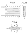
- Fig. 1A is a front view of a shield panel used for forming a magnetic shielding system according to the present invention
- Fig. 1B is a side view thereof
- Fig. 1C is a top view thereof.
- This shield panel comprises magnetic ribbons 1, a deformable non-magnetic material (sponge) 2 and a coil 3.
- a winding core composed of the magnetic ribbons 1 and the sponge 2 is formed into a cylinder with open ends by rolling this shield panel in the direction of arrow ⁇ or ⁇ .
- a axial direction of the cylinder is parallel or substantially parallel to a longitudinal direction of each of the magnetic ribbons 1.
- a magnetic shielding system according to the present invention is formed.
- the magnetic ribbons 1 are composed of Metglas 2705M (brand name by Allied, Inc. in USA) for example, and the winding core formed of the sponge 2 is composed of a deformable non-magnetic material such as a paper, a resin or the like.
- a winding direction of the coil 3 is perpendicular or substantially perpendicular to the longitudinal direction of each of the magnetic ribbons 1.
- each of the magnetic ribbons 1 has an easy axis of magnetization in the longitudinal direction thereof, and is formed so that the magnetic flux path of a magnetic shaking field is closed by arranging the magnetic ribbons so as to close the coil 3, as described after in detail.
- Figs. 2A to 2D are figures for explaining a method of manufacturing another magnetic shielding system according to the present invention.
- magnetic ribbons 12 (Fig. 2B) composed of a cobalt-based amorphous material are stuck on the side face of a cylindrical pipe 11 (Fig. 2A) composed of a non-magnetic material such as paper, resin, FRP (fiber reinforced plastics), non-magnetic metal, carbon fiber or the like.
- a coil 13 is wound around the pipe 11 and the magnetic ribbons 12 at perpendicular or substantially perpendicular to the easy axis of magnetization of magnetic ribbons 12 (Fig. 2C) and the magnetic path is closed by folding the magnetic ribbons 12, and the coil 13 is wound at the opposite direction to the winding direction shown in Fig. 2C (Fig. 2D).
- the magnetic ribbons 12 are formed into a cylinder with open ends and a axial direction of the cylinder is parallel or substantially parallel to a longitudinal direction of the magnetic ribbons 12.
- the magnetic flux path of a magnetic shaking field is closed by arranging the magnetic ribbons so as to close the coil 13.
- a magnetic shielding system in comparison with that of a conventional magnetic shielding system described in U. S. Patent No. 6,229,423 B1 filed on May 8, 2001.
- a longitudinal direction of each of magnetic ribbons 21 is parallel or substantially parallel to the axial direction of the cylinder and a winding direction of a coil for generating a magnetic shaking field is also parallel or substantially parallel to the axial direction of the cylinder.
- an open magnetic path ⁇ 1-1 or ⁇ 1-2 formed by an easy axis of magnetization of a magnetic ribbon is formed.
- a magnetic shaking field ⁇ 2 generated by the coil is formed and this magnetic shaking field ⁇ 2 is perpendicular to the magnetic path ⁇ 1-1 or ⁇ 1-2. Therefore, as it is impossible to close the magnetic shaking field ⁇ 2 generated by the coil due to the open magnetic paths ⁇ 1-1 or ⁇ 1-2 formed by the easy axis of magnetization of the magnetic ribbon, the efficiency of magnetic shaking decreases.
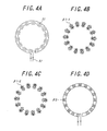
- a magnetic shielding system As shown in Fig. 4A, magnetic ribbons 31 are arranged so as to close a coil 32.
- Fig. 4B or 4C closed magnetic path ⁇ 1-1 or ⁇ 1-2 formed by an easy axis of magnetization of each of the magnetic ribbons is formed, and as shown in Fig. 4D, magnetic flux path B2 of a magnetic shaking field generated by the coil is formed in parallel to the magnetic path ⁇ 1-1 or ⁇ 1-2. Therefore, as the magnetic shaking field ⁇ 2 formed by the coil are closed by the closed magnetic path ⁇ 1-1 or ⁇ 1-2 generated by the easy axis of magnetization, the efficiency of shaking magnetic increases.
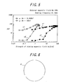
- Fig. 5 is a figure showing the shield ratios in a axial direction of a conventional magnetic shielding system and a magnetic shielding system according to the present invention.
- the theoretical maximum shield ratio ASF is about 100 however large the magnetic permeability and thickness of a magnetic body to be used are made.
- the maximum value of the shield ratio ASF is realized by a magnetic shaking field of about 2.4 A/m.
- a shaking current required for obtain an optimum shielding effect against a magnetic field in the axial direction of the cylinder about 1/10 smaller than that of a conventional magnetic shielding system as shown in Fig. 3A and thus make it substantially same as a current required for obtaining a shield effect against a magnetic field in a radial direction of the cylinder.
- a sufficient shield function against a magnetic field in the axial direction of the cylinder with a relatively small shaking current.
- the present invention is not limited to the above-described embodiments but can be modified and deformed in various manners.
- the magnetic shielding system according to the present invention is formed with the winding core or the inner core composed of a non-magnetic material, however, it is also possible to make the magnetic shielding system according to the present invention without the winding core or the inner core.
- the magnetic material for forming the magnetic ribbon can be composed of an amorphous alloy, a nano-crystalline alloy or the like other than Metglas 2705M (trade name by Allied, Inc. in USA).
- the magnetic shielding system is formed with a single shield panel, however, it is also possible to make the magnetic shielding system according to the present invention by combining a plurality of curved shield panels in direction ⁇ or ⁇ .
- Fig. 6 shows a magnetic shielding system according to the present invention formed by combining three curved magnetic shield panels 4.
- the magnetic shielding system according to the present invention is utilized in a field requiring a magnetically shielded space and the following are examples thereof:
Landscapes
- Engineering & Computer Science (AREA)
- Power Engineering (AREA)
- Physics & Mathematics (AREA)
- Condensed Matter Physics & Semiconductors (AREA)
- General Physics & Mathematics (AREA)
- Shielding Devices Or Components To Electric Or Magnetic Fields (AREA)
- Details Of Measuring And Other Instruments (AREA)
Applications Claiming Priority (2)
| Application Number | Priority Date | Filing Date | Title |
|---|---|---|---|
| JP2003320422A JP2005093452A (ja) | 2003-09-11 | 2003-09-11 | 磁気シールド装置 |
| JP2003320422 | 2003-09-11 |
Publications (2)
| Publication Number | Publication Date |
|---|---|
| EP1515149A2 true EP1515149A2 (fr) | 2005-03-16 |
| EP1515149A3 EP1515149A3 (fr) | 2006-06-28 |
Family
ID=34132043
Family Applications (1)
| Application Number | Title | Priority Date | Filing Date |
|---|---|---|---|
| EP04021139A Withdrawn EP1515149A3 (fr) | 2003-09-11 | 2004-09-06 | Système de blindage magnétique |
Country Status (3)
| Country | Link |
|---|---|
| US (1) | US20050110603A1 (fr) |
| EP (1) | EP1515149A3 (fr) |
| JP (1) | JP2005093452A (fr) |
Cited By (2)
| Publication number | Priority date | Publication date | Assignee | Title |
|---|---|---|---|---|
| WO2012141670A1 (fr) * | 2011-04-11 | 2012-10-18 | Sosnytskyy Volodymyr Mykolayovych | Dispositif de protection d'unité de détection de magnétocardiographe |
| CN109239624A (zh) * | 2018-08-30 | 2019-01-18 | 江苏赛诺格兰医疗科技有限公司 | 一种检测磁屏蔽材料磁屏蔽性能的测试系统和测试方法 |
Families Citing this family (2)
| Publication number | Priority date | Publication date | Assignee | Title |
|---|---|---|---|---|
| JP5076161B2 (ja) * | 2006-12-28 | 2012-11-21 | 国立大学法人九州大学 | 分離型磁気シールド装置 |
| JP2013197290A (ja) * | 2012-03-19 | 2013-09-30 | Ohtama Co Ltd | 磁気シールド部材 |
Family Cites Families (3)
| Publication number | Priority date | Publication date | Assignee | Title |
|---|---|---|---|---|
| US4340770A (en) * | 1979-09-21 | 1982-07-20 | Allied Corporation | Enhancement of the magnetic permeability in glassy metal shielding |
| JP3020169B1 (ja) * | 1999-05-10 | 2000-03-15 | 九州大学長 | 磁気シ―ルド装置 |
| US6563474B2 (en) * | 2000-12-21 | 2003-05-13 | Lear Corporation | Remote access device having multiple inductive coil antenna |
-
2003
- 2003-09-11 JP JP2003320422A patent/JP2005093452A/ja active Pending
-
2004
- 2004-09-02 US US10/932,110 patent/US20050110603A1/en not_active Abandoned
- 2004-09-06 EP EP04021139A patent/EP1515149A3/fr not_active Withdrawn
Non-Patent Citations (2)
| Title |
|---|
| NAGASHIMA K ET AL: "ADAPTIVE COMPENSATION OF MAGNETIC FIELDS INSIDE AN OPEN CYLINDRICAL MAGNETIC SHIELD" IEEE TRANSACTIONS ON MAGNETICS, IEEE SERVICE CENTER, NEW YORK, NY, US, vol. 39, no. 5, PART 2, September 2003 (2003-09), pages 3223-3225, XP001174490 ISSN: 0018-9464 * |
| PAPERNO E ET AL: "Effect of magnetic anisotropy on magnetic shaking" JOURNAL OF APPLIED PHYSICS, AMERICAN INSTITUTE OF PHYSICS. NEW YORK, US, vol. 85, no. 8, 15 April 1999 (1999-04-15), pages 4645-4647, XP012047209 ISSN: 0021-8979 * |
Cited By (2)
| Publication number | Priority date | Publication date | Assignee | Title |
|---|---|---|---|---|
| WO2012141670A1 (fr) * | 2011-04-11 | 2012-10-18 | Sosnytskyy Volodymyr Mykolayovych | Dispositif de protection d'unité de détection de magnétocardiographe |
| CN109239624A (zh) * | 2018-08-30 | 2019-01-18 | 江苏赛诺格兰医疗科技有限公司 | 一种检测磁屏蔽材料磁屏蔽性能的测试系统和测试方法 |
Also Published As
| Publication number | Publication date |
|---|---|
| EP1515149A3 (fr) | 2006-06-28 |
| JP2005093452A (ja) | 2005-04-07 |
| US20050110603A1 (en) | 2005-05-26 |
Similar Documents
| Publication | Publication Date | Title |
|---|---|---|
| US5012217A (en) | Integrated active shielded magnet system | |
| JP4773515B2 (ja) | 永久磁石、mriで使用するための永久磁石を備えた磁気装置およびその製造方法 | |
| EP0284439B1 (fr) | Dispositif pour la génération d'un champ magnétique | |
| US4839059A (en) | Clad magic ring wigglers | |
| US10332718B1 (en) | Compact deflecting magnet | |
| JPH06304150A (ja) | 磁気共鳴映像のための磁石 | |
| KR20010020798A (ko) | 자기센서 및 그 제조방법 | |
| CN111009374B (zh) | 一种具有紧凑线圈结构的核磁共振超导磁体 | |
| EP1515149A2 (fr) | Système de blindage magnétique | |
| JP4021982B2 (ja) | ハイブリッド型ウイグラ | |
| JP4706082B2 (ja) | 磁気シールド装置 | |
| US5084690A (en) | Stepped magnetic field source | |
| JP3020169B1 (ja) | 磁気シ―ルド装置 | |
| US5805044A (en) | Field free chamber in permanent magnet solenoids | |
| CN1926443B (zh) | 具有增强器铁的磁共振成像扫描仪 | |
| JP4897608B2 (ja) | 超電導電磁石 | |
| US10790078B2 (en) | Apparatus and method for magnetic field compression | |
| JP6628407B2 (ja) | 低漏洩シェイキング式開放型磁気シールド構造 | |
| JP5900014B2 (ja) | 磁気シールド装置 | |
| Schmidt et al. | A 4 Tesla/1 meter superferric MRI magnet | |
| JP2003257751A (ja) | 磁気シールド装置 | |
| JPH0918184A (ja) | 磁気シールドルーム | |
| JPH05121227A (ja) | Mri装置用のマグネツト | |
| JP7504889B2 (ja) | 磁化構造の消磁 | |
| US5227754A (en) | Magnetic flux transmission system |
Legal Events
| Date | Code | Title | Description |
|---|---|---|---|
| PUAI | Public reference made under article 153(3) epc to a published international application that has entered the european phase |
Free format text: ORIGINAL CODE: 0009012 |
|
| 17P | Request for examination filed |
Effective date: 20040906 |
|
| AK | Designated contracting states |
Kind code of ref document: A2 Designated state(s): AT BE BG CH CY CZ DE DK EE ES FI FR GB GR HU IE IT LI LU MC NL PL PT RO SE SI SK TR |
|
| AX | Request for extension of the european patent |
Extension state: AL HR LT LV MK |
|
| PUAL | Search report despatched |
Free format text: ORIGINAL CODE: 0009013 |
|
| AK | Designated contracting states |
Kind code of ref document: A3 Designated state(s): AT BE BG CH CY CZ DE DK EE ES FI FR GB GR HU IE IT LI LU MC NL PL PT RO SE SI SK TR |
|
| AX | Request for extension of the european patent |
Extension state: AL HR LT LV MK |
|
| AKX | Designation fees paid |
Designated state(s): DE |
|
| STAA | Information on the status of an ep patent application or granted ep patent |
Free format text: STATUS: THE APPLICATION IS DEEMED TO BE WITHDRAWN |
|
| 18D | Application deemed to be withdrawn |
Effective date: 20061230 |