EP1515091B1 - Einbaubackofen mit belüfteten Seitenwänden - Google Patents
Einbaubackofen mit belüfteten Seitenwänden Download PDFInfo
- Publication number
- EP1515091B1 EP1515091B1 EP04352010.5A EP04352010A EP1515091B1 EP 1515091 B1 EP1515091 B1 EP 1515091B1 EP 04352010 A EP04352010 A EP 04352010A EP 1515091 B1 EP1515091 B1 EP 1515091B1
- Authority
- EP
- European Patent Office
- Prior art keywords
- oven
- built
- face
- apertures
- air
- Prior art date
- Legal status (The legal status is an assumption and is not a legal conclusion. Google has not performed a legal analysis and makes no representation as to the accuracy of the status listed.)
- Expired - Lifetime
Links
- 239000002184 metal Substances 0.000 claims description 4
- 238000005273 aeration Methods 0.000 claims 1
- 210000002816 gill Anatomy 0.000 description 22
- 238000009434 installation Methods 0.000 description 10
- 238000001816 cooling Methods 0.000 description 8
- 238000009423 ventilation Methods 0.000 description 6
- 230000003071 parasitic effect Effects 0.000 description 2
- 239000000470 constituent Substances 0.000 description 1
- 210000005069 ears Anatomy 0.000 description 1
- 239000000463 material Substances 0.000 description 1
Images

Classifications
-
- F—MECHANICAL ENGINEERING; LIGHTING; HEATING; WEAPONS; BLASTING
- F24—HEATING; RANGES; VENTILATING
- F24C—DOMESTIC STOVES OR RANGES ; DETAILS OF DOMESTIC STOVES OR RANGES, OF GENERAL APPLICATION
- F24C15/00—Details
- F24C15/008—Illumination for oven cavities
-
- F—MECHANICAL ENGINEERING; LIGHTING; HEATING; WEAPONS; BLASTING
- F24—HEATING; RANGES; VENTILATING
- F24C—DOMESTIC STOVES OR RANGES ; DETAILS OF DOMESTIC STOVES OR RANGES, OF GENERAL APPLICATION
- F24C15/00—Details
- F24C15/006—Arrangements for circulation of cooling air
-
- F—MECHANICAL ENGINEERING; LIGHTING; HEATING; WEAPONS; BLASTING
- F21—LIGHTING
- F21W—INDEXING SCHEME ASSOCIATED WITH SUBCLASSES F21K, F21L, F21S and F21V, RELATING TO USES OR APPLICATIONS OF LIGHTING DEVICES OR SYSTEMS
- F21W2131/00—Use or application of lighting devices or systems not provided for in codes F21W2102/00-F21W2121/00
- F21W2131/30—Lighting for domestic or personal use
- F21W2131/307—Lighting for domestic or personal use for ovens
Definitions
- the present invention relates to a built-in oven with ventilated sidewalls.
- Built-in ovens are intended to take place in a built-in cabinet, which is usually integrated into a kitchen. Such an oven must meet standards that impose a limit temperature on the flush-mounted furniture. It is therefore known to create an air flow at the side walls of a built-in oven to limit the temperature of the built-in cabinet.
- a first type of furniture is substantially cubic form and only the front face is open to allow the introduction of the built-in oven.
- the other type of furniture comprises, in addition to the opening for the introduction of the oven, openings on the upper and lower faces for allowing the passage of an air flow.
- the cooling of the installation unit is different according to the type of furniture and this poses problems of development of aeraulic of the built-in oven.
- the figure 1 annexed diagrammatically shows in side view a furnace 2 intended to be embedded in a built-in cabinet 4 closed.
- this oven 2 comprises a fan 6 disposed at the rear of the oven 2, in its upper part.
- Gills 8 are provided on the side walls of the oven 2, at the rear thereof, to allow fresh air supply of the fan 6.
- FIG 2 there is shown a technically similar oven but intended to be installed in an open cabinet.
- the same references as those of the figure 1 are used to designate elements Similar.
- the air supply of the fan 6 is done via 8 on the side walls of the furnace 2.
- these openings 8 are disposed in a substantially median position relative to the oven.
- the fresh air supplying the fan 6 passes through the openings and then comes either from openings provided for this purpose in the front face of the furnace 2 or openings made at the bottom of the installation unit 4.
- the first arrows 14 symbolize the flow of air supplying the fan 6 through the openings 8 from the front face of the furnace 2 and the second arrows 16 symbolize the air flow supplying the fan 6 through the side openings 8 from the openings made at the bottom of the cabinet. 4. Note that if such an oven is placed in a closed cabinet, the air flow symbolized by the arrows 16 is no longer possible and the entire rear part of the oven and the built-in cabinet no longer broken down.
- the document DE-A-2806158 shows a built-in oven and represents the state of the art closest.
- the present invention therefore aims to provide a built-in oven that can both be embedded in a closed type of built-in furniture in an open type of furniture installation.
- a furnace has no additional cost compared to comparable built-in furnaces of the prior art.
- a built-in oven with ventilated side walls comprising a front face and a rear face connected by the side walls, a fan placed inside the oven and supplied with fresh air through vents made in at least one wall. side of the oven.
- At least one of the openings, on each side face provided with openings, is made close to the rear face of the oven and said openings are each careened so as to promote the entry of air into the air. from the front of the oven and forming an obstacle for air from the back of the oven.
- the embodiment proposed by the invention makes it possible to favor the air coming from the front of the oven for the air supply of the openings.
- the cabinet in which the oven is located is open or closed in its rear part, although the openings are arranged at the rear of the oven, the air feeding these openings will come mainly from the front of the oven allowing and a ventilation of the side walls of this oven in all cases.
- the faired openings are covered by a cover forming a channel and are preferably in close proximity to the closed side of the channel formed by this hood.
- the length of the channel located between the front opening of the channel and the hearing is between 0.5 and 10 cm.
- the faired openings are advantageously in the rear quarter of the corresponding side wall, preferably in the immediate vicinity of the rear face of the oven.
- An embodiment of the present invention provides that said gills are in the form of a slit substantially perpendicular to a flow of air from the front of the furnace and pointing towards its rear face.
- the rear face of the furnace advantageously comprises a sheet having two flanges perpendicular to the rear face and provided in particular for fixing said sheet on two lateral faces of the furnace by partially covering these lateral faces, and the covers for the gills are then made for example by stamping on said flanges of the rear sheet.
- an oven according to the invention comprises at least one lamp in order to illuminate the inside of the oven
- a ventilation opening placed near said lamp is advantageous because it allows a ventilation of the lamp.
- the temperatures at the lamp are limited and it is possible to use in this lamp a common bulb and not a bulb specifically designed to withstand high temperatures.
- the present invention also relates to an assembly formed by a built-in oven according to the invention and a built-in cabinet, characterized in that each fairing corresponding to an opening is flush with the inner face of the installation unit.
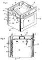
- the furnace 2 represented on Figures 4 and 5 (partially diagrammed on the figures 3 ) comprises a front face 20 on which is pivotally mounted a door 22 to access the oven and a control panel 24 carrying the various control buttons for a user to operate the oven 2. Opposite the front face 20 is the rear face 26. Between these front 20 and rear faces 26, the oven 2 has four lateral faces: an upper face 28, a lower face 30 and two side faces 32.
- Each side face 32 consists essentially of a side wall 34 made of sheet metal. Such a wall defines the enclosure of the oven and has in its upper part a handle 36.
- the gills 8 are made on the side walls 34.
- the drawing shows only one side face 32 (the left side face) of the oven 2. It is considered here, apart from some details unrelated to the invention, that the Side face 32 right, not visible in the drawing, is identical, to a symmetry, the 32 left face visible in this drawing.
- Each side wall 34 carries four louvers 8. The latter are in the form of vertical slots, that is to say that they are parallel to the edge 38 separating a side face 32 of the rear face 26. These 8 are arranged one above the other and are evenly distributed over the height of the furnace chamber 2. These gills 8 are made as close as possible to the edge 38.
- a fairing 40 is associated with each hearing 8 and promotes the introduction into the hearing 8 of the air in from the front face 20 of the oven.
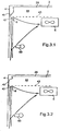
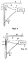
- This fairing 40 is of various shapes ( Figures 3.1 to 3.4 ). It is open towards the front of the oven 2 while it is closed on the back.
- the louvers 8 are preferably made in the immediate vicinity of the rear face of each fairing 40 corresponding. This creates a channel 42 more or less long in which must pass the air sucked by the fan 6 and through the openings 8.
- the shroud 40 is sized to minimize the residual space between itself and the furniture of 4.
- the air can come only from the front of the oven. All the air then supplying the fan 6 and passing through the openings 8 then runs along the corresponding wall 34 thus causing cooling thereof during operation of the furnace 2. As indicated above, the gills 8 are arranged as close to the rear face 26 of the oven 2 so as to optimize the cooling of the side wall 34.
- a dotted line 43 symbolizes on Figures 3.1 to 3.4 the edge of an opening 44 possibly located at the rear of the installation unit 4. If such an opening 44 is present, fresh air passing through this opening 44 can also reach the fan 6 through the openings 8. It is clear on Figures 3.1 to 3.4 that many obstacles are found on the path of this air between the opening 44 and the fan 6. In fact, it must first of all that this air, or at least part of it, passes between the fairings 40 and the installation unit 4. It is then necessary that it turns around to enter the channels 42 allowing access to the gills 8. Because of these obstacles, most of the air passing through the 8 gills to supply the fan 6 will be air from the front of the oven. The parasitic air flow symbolized by an arrow 46 ( figure 3.4 ) does not significantly disturb the cooling of the side walls 34 of the oven 2.
- the fairing 40 is for example obtained by cutting and / or stamping of the side wall 34.
- the shroud 40 consists of a single flap folded outwardly. It suffices to make a U-shaped cutout in the corresponding lateral wall 34 and to bend outwardly from this wall the material lying between the branches of the U.
- a stamping is performed and the fairing 40 here forms a cover above the hearing 8. This cover is preferably closed on all three sides (back, bottom and top) to better channel the air to the hearing 8 .
- the shrouds 40 are made on the sheet forming the rear face 26 of the furnace 2.
- This sheet has flanges 48 which partially cover the side faces 32.
- These flanges 38 are initially provided for fixing the sheet forming the rear face 26 on the side walls 34.
- the shrouds 40 are then made at the free edge of the rim 38. No cutting is necessary to achieve the hearing 8 and the opening of the fairings 40.
- the side wall 34 has near the rear face 26 a recess inwardly of the oven at the hearing 8.
- the flange forming the fairing 40 partially covers the recess.
- the side wall 34 is flat and the rim of the rear face 26 covers the hearing 8 and a portion of the side wall 34 forming the shroud 40.
- the present invention provides for the furnace described an advantageous embodiment in which the air flow along the side walls 34 is used to cool a lamp 50 provided to illuminate the enclosure of the furnace 2.
- a lamp 50 provided to illuminate the enclosure of the furnace 2.
- it is provided in the side wall 34 at least one hearing 52 near the lamp 50.
- twelve ears 52 ( figure 5 ) of circular shape and small diameter (a few millimeters) are provided.
- the ventilation of the lamp 50 limits the temperature thereof during operation of the oven. It then becomes possible to use in this lamp 50 a common bulb and not a bulb specifically designed to withstand high temperatures.
- the oven 2 according to the invention can take place as well in a built-in cabinet 4 closed as in an open cabinet 4 open.
- the conformation of the air inlets supplying the fan 6 makes it possible in both cases to ensure good cooling of the side walls 34 of the oven 2.
- part of the air flow cooling the side walls can be used to cool the ( or the) lamp (s) 50.
- the present invention thus makes it possible to save money because it is no longer necessary to provide, for the same type of oven, a version intended for an open installation unit and another version intended for to a closed cabinet.
- a sensible economy can be achieved at the cost of the lamp used.
- the two side walls 34 are identical. This is the case for the oven shown in the drawing. It is noted on the wall 34 shown the presence of two sets of gills 52. Since the lamp 50 is not centered in the oven, it is necessary to provide this second series of gills 52 so that a side wall 34 can be exchanged with the other side wall. With regard to the gills 8, it is possible to have such gills towards the front face of the oven. In the embodiment shown on the Figures 4 and 5 these gills are then covered by a flange 54 used for assembling the various constituent parts of the furnace 2. These gills are then plugged and no air flow can pass through them.
- the shape, the quantity, the arrangement, etc. of the gills as described are not limiting.
- the presence of gills at a lamp is optional.
- the present invention can be applied to all types of built-in oven, whatever the position of the fan in the oven.
Landscapes
- Engineering & Computer Science (AREA)
- Chemical & Material Sciences (AREA)
- Combustion & Propulsion (AREA)
- Mechanical Engineering (AREA)
- General Engineering & Computer Science (AREA)
- Electric Stoves And Ranges (AREA)
- Baking, Grill, Roasting (AREA)
Claims (8)
- Einbaubackofen (2) mit belüfteten Seitenwänden (34), der eine Vorderseite (20) und eine Rückseite (26) aufweist, die über die Seitenwände (34) verbunden sind, einen Lüfter (6), der innerhalb des Backofens (2) angeordnet ist und dem über Öffnungen (8), die in mindestens einer Seitenwand (34) des Backofens ausgebildet sind, Frischluft zugeführt wird, wobei auf jeder mit Öffnungen versehenen Seitenfläche (34) mindestens eine der Öffnungen (8) in der Nähe der Rückseite (26) des Backofens ausgebildet ist, dadurch gekennzeichnet, dass die Öffnungen (8) jeweils so verkleidet sind, dass sie den Eintritt der Luft, die von der Vorderseite (20) des Backofens stammt, begünstigen und ein Hindernis für die Luft bilden, die von dem hinteren Teil des Backofens (2) stammt.
- Einbaubackofen nach Anspruch 1, dadurch gekennzeichnet, dass die verkleideten Öffnungen (8) von einer einen Kanal bildenden Kappe (40) bedeckt sind und in unmittelbarer Nähe der geschlossenen Seite des durch diese Kappe (40) gebildeten Kanals (42) liegen.
- Einbaubackofen nach Anspruch 2, dadurch gekennzeichnet, dass die Länge des Kanals (42), die zwischen dem vorderen Einlass des Kanals und der Öffnung (8) liegt, zwischen 0,5 und 10 cm beträgt.
- Einbaubackofen nach einem Ansprüche 1 bis 3, dadurch gekennzeichnet, dass die verkleideten Öffnungen (8) im hinteren Viertel der entsprechenden Seitenwand (34), vorzugsweise in unmittelbarer Nähe der Rückseite (26) des Backofens liegen.
- Einbaubackofen nach einem der Ansprüche 1 bis 4, dadurch gekennzeichnet, dass die Öffnungen (8) in Form eines Spalts vorliegen, der im Wesentlichen senkrecht zu einem Luftstrom verläuft, der von der Vorderseite (20) des Backofens ausgeht und sich zu seiner Rückseite (26) bewegt.
- Einbaubackofen nach Anspruch 2, dadurch gekennzeichnet, dass die Rückseite (26) des Backofens ein Blech mit zwei Rändern (48) aufweist, die senkrecht zur Rückseite (26) verlaufen und insbesondere für die Befestigung des Blechs an zwei Seitenflächen (32) des Backofens vorgesehen sind, wobei diese Seitenflächen (34) teilweise bedeckt sind, und die Abdeckungen (40) für die Öffnungen (8) durch Tiefziehen an den Rändern (48) des hinteren Blechs ausgebildet werden.
- Einbaubackofen nach einem der Ansprüche 1 bis 6, dadurch gekennzeichnet, dass der Backofen (2) mindestens eine Lampe (50) zur Beleuchtung des Backofeninneren aufweist und an einer Seitenwand (34), die mit einer verkleideten Öffnung (8) versehen ist, eine Belüftungsöffnung (52) vorgesehen ist, die in der Nähe der Lampe (50) angeordnet ist.
- Baugruppe, die durch einen Einbaubackofen (2) nach einem der Ansprüche 1 bis 7 und ein Einbaumöbel (4) gebildet ist, dadurch gekennzeichnet, dass jede Verkleidung, die einer Öffnung (8) entspricht, die Innenfläche des Einbaumöbels (4) leicht berührt.
Applications Claiming Priority (2)
| Application Number | Priority Date | Filing Date | Title |
|---|---|---|---|
| FR0309243 | 2003-07-28 | ||
| FR0309243A FR2858394B1 (fr) | 2003-07-28 | 2003-07-28 | Four encastrable a parois laterales ventilees |
Publications (3)
| Publication Number | Publication Date |
|---|---|
| EP1515091A2 EP1515091A2 (de) | 2005-03-16 |
| EP1515091A3 EP1515091A3 (de) | 2011-11-02 |
| EP1515091B1 true EP1515091B1 (de) | 2016-10-19 |
Family
ID=34043594
Family Applications (1)
| Application Number | Title | Priority Date | Filing Date |
|---|---|---|---|
| EP04352010.5A Expired - Lifetime EP1515091B1 (de) | 2003-07-28 | 2004-07-27 | Einbaubackofen mit belüfteten Seitenwänden |
Country Status (3)
| Country | Link |
|---|---|
| EP (1) | EP1515091B1 (de) |
| ES (1) | ES2609681T3 (de) |
| FR (1) | FR2858394B1 (de) |
Families Citing this family (2)
| Publication number | Priority date | Publication date | Assignee | Title |
|---|---|---|---|---|
| KR101231321B1 (ko) * | 2006-04-27 | 2013-02-07 | 엘지전자 주식회사 | 제습기 |
| EP2901084B1 (de) * | 2012-09-28 | 2017-08-02 | Arçelik Anonim Sirketi | Ofen mit erhöhter lüftungseffizienz |
Family Cites Families (4)
| Publication number | Priority date | Publication date | Assignee | Title |
|---|---|---|---|---|
| DE2310290C3 (de) * | 1973-03-01 | 1978-07-13 | Bosch-Siemens Hausgeraete Gmbh, 7000 Stuttgart | Einbaubackofen mit Mitteln zur pyrolyttschen Selbstreinigung |
| DE2806158C2 (de) * | 1978-02-14 | 1982-12-23 | Bosch-Siemens Hausgeräte GmbH, 7000 Stuttgart | Doppelbackofen |
| US4865864A (en) * | 1985-03-27 | 1989-09-12 | Rijswijck Willem V | Air heated oven and heating method |
| DE19504673C2 (de) * | 1995-02-13 | 1998-04-30 | Bosch Siemens Hausgeraete | Einbaugargerät-Kühlung |
-
2003
- 2003-07-28 FR FR0309243A patent/FR2858394B1/fr not_active Expired - Lifetime
-
2004
- 2004-07-27 ES ES04352010.5T patent/ES2609681T3/es not_active Expired - Lifetime
- 2004-07-27 EP EP04352010.5A patent/EP1515091B1/de not_active Expired - Lifetime
Non-Patent Citations (1)
| Title |
|---|
| None * |
Also Published As
| Publication number | Publication date |
|---|---|
| FR2858394B1 (fr) | 2005-10-14 |
| ES2609681T3 (es) | 2017-04-21 |
| FR2858394A1 (fr) | 2005-02-04 |
| EP1515091A3 (de) | 2011-11-02 |
| EP1515091A2 (de) | 2005-03-16 |
Similar Documents
| Publication | Publication Date | Title |
|---|---|---|
| EP0583180B1 (de) | Kühlanlage für Tür eines Haushaltsbackofens | |
| EP2967254B1 (de) | Grill mit mindestens zwei abnehmbaren panelen | |
| EP0376791B1 (de) | Träger für Regelorgane an Haushaltsgeräten | |
| WO2019243739A1 (fr) | Dispositif de ventilation pour véhicule automobile | |
| EP1473449B1 (de) | Vorrichtung zur Steuerung des Luftstromes für ein Kühlmodul eines Kraftfahrzeugs | |
| FR2858394A1 (fr) | Four encastrable a parois laterales ventilees | |
| EP2298143A1 (de) | Toaster mit schwenkbarer Seitentür | |
| EP2843314B1 (de) | Luftzirkulationsvorrichtung, insbesondere für Kaminhaube, und mit einer solchen Vorrichtung ausgestattete Kaminhaube | |
| EP2251220B1 (de) | Ansaugvorrichtung | |
| CA2491346C (fr) | Systeme d'aeration d'un boitier d'appareillage electrique ou electronique | |
| EP2978347B1 (de) | Ofen | |
| EP1215943B1 (de) | Mikrowellenofen | |
| FR2773209A1 (fr) | Four a micro-ondes comportant un element formant guide pour une evacuation de gaz | |
| FR2768800A1 (fr) | Amelioration de fours de cuisson domestiques a encastrer | |
| FR3059085B1 (fr) | Dispositif de ventilation notamment pour habitation | |
| EP2736313B1 (de) | Drehzahlregler und System, das eine Architektur zur Verstärkung der Dichtigkeit des Drehzahlreglers umfasst | |
| EP0614779A1 (de) | Steuertafel mit integrierter Beleuchtung, insbesondere für Kraftfahrzeuge | |
| EP1266592B1 (de) | Fertigmontagesatz für Einbaubareelemente eines Haushaltgeräts in einer Nische | |
| EP1936281B1 (de) | Brennofen, der mindestens einen Verengungsmechanismus für das Durchlassprofil des Luftstroms umfasst | |
| FR3024745A1 (fr) | Volet basculant pour une ouverture de batiment d'elevage et batiment qui en est equipe | |
| EP4040052B1 (de) | System mit heizmodulsatz | |
| EP0793054A2 (de) | Blende für Kraftfahrzeugscheinwerfer und Scheinwerfer versehen mit einer solchen | |
| FR3140203A1 (fr) | Accessoire de protection pour porte d’armoire électrique, porte et armoire électrique intégrant ledit accessoire | |
| EP0875722A1 (de) | Heissluftdiffusionssystem für Kaminhaube | |
| FR3054843B1 (fr) | Tricotin semi-automatique demontable |
Legal Events
| Date | Code | Title | Description |
|---|---|---|---|
| PUAI | Public reference made under article 153(3) epc to a published international application that has entered the european phase |
Free format text: ORIGINAL CODE: 0009012 |
|
| AK | Designated contracting states |
Kind code of ref document: A2 Designated state(s): AT BE BG CH CY CZ DE DK EE ES FI FR GB GR HU IE IT LI LU MC NL PL PT RO SE SI SK TR |
|
| AX | Request for extension of the european patent |
Extension state: AL HR LT LV MK |
|
| RAP1 | Party data changed (applicant data changed or rights of an application transferred) |
Owner name: FAGORBRANDT SAS |
|
| PUAL | Search report despatched |
Free format text: ORIGINAL CODE: 0009013 |
|
| AK | Designated contracting states |
Kind code of ref document: A3 Designated state(s): AT BE BG CH CY CZ DE DK EE ES FI FR GB GR HU IE IT LI LU MC NL PL PT RO SE SI SK TR |
|
| AX | Request for extension of the european patent |
Extension state: AL HR LT LV MK |
|
| RIC1 | Information provided on ipc code assigned before grant |
Ipc: F24C 15/00 20060101AFI20110927BHEP Ipc: F21V 29/02 20060101ALI20110927BHEP |
|
| 17P | Request for examination filed |
Effective date: 20120416 |
|
| AKX | Designation fees paid |
Designated state(s): AT BE BG CH CY CZ DE DK EE ES FI FR GB GR HU IE IT LI LU MC NL PL PT RO SE SI SK TR |
|
| 19U | Interruption of proceedings before grant |
Effective date: 20140411 |
|
| 19W | Proceedings resumed before grant after interruption of proceedings |
Effective date: 20150701 |
|
| RAP1 | Party data changed (applicant data changed or rights of an application transferred) |
Owner name: GROUPE BRANDT |
|
| 111Z | Information provided on other rights and legal means of execution |
Free format text: AT BE BG CH CY CZ DE DK EE ES FI FR GB GR HU IE IT LU MC NL PL PT RO SE SI SK TR Effective date: 20150915 |
|
| RIC1 | Information provided on ipc code assigned before grant |
Ipc: F24C 15/00 20060101AFI20160301BHEP |
|
| GRAP | Despatch of communication of intention to grant a patent |
Free format text: ORIGINAL CODE: EPIDOSNIGR1 |
|
| INTG | Intention to grant announced |
Effective date: 20160411 |
|
| GRAJ | Information related to disapproval of communication of intention to grant by the applicant or resumption of examination proceedings by the epo deleted |
Free format text: ORIGINAL CODE: EPIDOSDIGR1 |
|
| GRAR | Information related to intention to grant a patent recorded |
Free format text: ORIGINAL CODE: EPIDOSNIGR71 |
|
| GRAS | Grant fee paid |
Free format text: ORIGINAL CODE: EPIDOSNIGR3 |
|
| INTC | Intention to grant announced (deleted) | ||
| GRAA | (expected) grant |
Free format text: ORIGINAL CODE: 0009210 |
|
| AK | Designated contracting states |
Kind code of ref document: B1 Designated state(s): AT BE BG CH CY CZ DE DK EE ES FI FR GB GR HU IE IT LI LU MC NL PL PT RO SE SI SK TR |
|
| INTG | Intention to grant announced |
Effective date: 20160912 |
|
| REG | Reference to a national code |
Ref country code: GB Ref legal event code: FG4D Free format text: NOT ENGLISH |
|
| REG | Reference to a national code |
Ref country code: CH Ref legal event code: EP |
|
| REG | Reference to a national code |
Ref country code: AT Ref legal event code: REF Ref document number: 838699 Country of ref document: AT Kind code of ref document: T Effective date: 20161115 |
|
| REG | Reference to a national code |
Ref country code: IE Ref legal event code: FG4D Free format text: LANGUAGE OF EP DOCUMENT: FRENCH |
|
| REG | Reference to a national code |
Ref country code: DE Ref legal event code: R096 Ref document number: 602004050152 Country of ref document: DE |
|
| REG | Reference to a national code |
Ref country code: NL Ref legal event code: MP Effective date: 20161019 |
|
| REG | Reference to a national code |
Ref country code: AT Ref legal event code: MK05 Ref document number: 838699 Country of ref document: AT Kind code of ref document: T Effective date: 20161019 |
|
| REG | Reference to a national code |
Ref country code: ES Ref legal event code: FG2A Ref document number: 2609681 Country of ref document: ES Kind code of ref document: T3 Effective date: 20170421 |
|
| PG25 | Lapsed in a contracting state [announced via postgrant information from national office to epo] |
Ref country code: SE Free format text: LAPSE BECAUSE OF FAILURE TO SUBMIT A TRANSLATION OF THE DESCRIPTION OR TO PAY THE FEE WITHIN THE PRESCRIBED TIME-LIMIT Effective date: 20161019 Ref country code: GR Free format text: LAPSE BECAUSE OF FAILURE TO SUBMIT A TRANSLATION OF THE DESCRIPTION OR TO PAY THE FEE WITHIN THE PRESCRIBED TIME-LIMIT Effective date: 20170120 |
|
| PG25 | Lapsed in a contracting state [announced via postgrant information from national office to epo] |
Ref country code: PL Free format text: LAPSE BECAUSE OF FAILURE TO SUBMIT A TRANSLATION OF THE DESCRIPTION OR TO PAY THE FEE WITHIN THE PRESCRIBED TIME-LIMIT Effective date: 20161019 Ref country code: NL Free format text: LAPSE BECAUSE OF FAILURE TO SUBMIT A TRANSLATION OF THE DESCRIPTION OR TO PAY THE FEE WITHIN THE PRESCRIBED TIME-LIMIT Effective date: 20161019 Ref country code: AT Free format text: LAPSE BECAUSE OF FAILURE TO SUBMIT A TRANSLATION OF THE DESCRIPTION OR TO PAY THE FEE WITHIN THE PRESCRIBED TIME-LIMIT Effective date: 20161019 Ref country code: FI Free format text: LAPSE BECAUSE OF FAILURE TO SUBMIT A TRANSLATION OF THE DESCRIPTION OR TO PAY THE FEE WITHIN THE PRESCRIBED TIME-LIMIT Effective date: 20161019 Ref country code: PT Free format text: LAPSE BECAUSE OF FAILURE TO SUBMIT A TRANSLATION OF THE DESCRIPTION OR TO PAY THE FEE WITHIN THE PRESCRIBED TIME-LIMIT Effective date: 20170220 |
|
| REG | Reference to a national code |
Ref country code: FR Ref legal event code: PLFP Year of fee payment: 14 |
|
| REG | Reference to a national code |
Ref country code: DE Ref legal event code: R097 Ref document number: 602004050152 Country of ref document: DE |
|
| PG25 | Lapsed in a contracting state [announced via postgrant information from national office to epo] |
Ref country code: SK Free format text: LAPSE BECAUSE OF FAILURE TO SUBMIT A TRANSLATION OF THE DESCRIPTION OR TO PAY THE FEE WITHIN THE PRESCRIBED TIME-LIMIT Effective date: 20161019 Ref country code: RO Free format text: LAPSE BECAUSE OF FAILURE TO SUBMIT A TRANSLATION OF THE DESCRIPTION OR TO PAY THE FEE WITHIN THE PRESCRIBED TIME-LIMIT Effective date: 20161019 Ref country code: CZ Free format text: LAPSE BECAUSE OF FAILURE TO SUBMIT A TRANSLATION OF THE DESCRIPTION OR TO PAY THE FEE WITHIN THE PRESCRIBED TIME-LIMIT Effective date: 20161019 Ref country code: EE Free format text: LAPSE BECAUSE OF FAILURE TO SUBMIT A TRANSLATION OF THE DESCRIPTION OR TO PAY THE FEE WITHIN THE PRESCRIBED TIME-LIMIT Effective date: 20161019 Ref country code: DK Free format text: LAPSE BECAUSE OF FAILURE TO SUBMIT A TRANSLATION OF THE DESCRIPTION OR TO PAY THE FEE WITHIN THE PRESCRIBED TIME-LIMIT Effective date: 20161019 |
|
| PLBE | No opposition filed within time limit |
Free format text: ORIGINAL CODE: 0009261 |
|
| STAA | Information on the status of an ep patent application or granted ep patent |
Free format text: STATUS: NO OPPOSITION FILED WITHIN TIME LIMIT |
|
| PG25 | Lapsed in a contracting state [announced via postgrant information from national office to epo] |
Ref country code: BG Free format text: LAPSE BECAUSE OF FAILURE TO SUBMIT A TRANSLATION OF THE DESCRIPTION OR TO PAY THE FEE WITHIN THE PRESCRIBED TIME-LIMIT Effective date: 20170119 |
|
| 26N | No opposition filed |
Effective date: 20170720 |
|
| PG25 | Lapsed in a contracting state [announced via postgrant information from national office to epo] |
Ref country code: SI Free format text: LAPSE BECAUSE OF FAILURE TO SUBMIT A TRANSLATION OF THE DESCRIPTION OR TO PAY THE FEE WITHIN THE PRESCRIBED TIME-LIMIT Effective date: 20161019 |
|
| REG | Reference to a national code |
Ref country code: CH Ref legal event code: PL |
|
| GBPC | Gb: european patent ceased through non-payment of renewal fee |
Effective date: 20170727 |
|
| REG | Reference to a national code |
Ref country code: IE Ref legal event code: MM4A |
|
| PG25 | Lapsed in a contracting state [announced via postgrant information from national office to epo] |
Ref country code: GB Free format text: LAPSE BECAUSE OF NON-PAYMENT OF DUE FEES Effective date: 20170727 Ref country code: IE Free format text: LAPSE BECAUSE OF NON-PAYMENT OF DUE FEES Effective date: 20170727 Ref country code: LI Free format text: LAPSE BECAUSE OF NON-PAYMENT OF DUE FEES Effective date: 20170731 Ref country code: CH Free format text: LAPSE BECAUSE OF NON-PAYMENT OF DUE FEES Effective date: 20170731 |
|
| REG | Reference to a national code |
Ref country code: BE Ref legal event code: MM Effective date: 20170731 |
|
| PG25 | Lapsed in a contracting state [announced via postgrant information from national office to epo] |
Ref country code: LU Free format text: LAPSE BECAUSE OF NON-PAYMENT OF DUE FEES Effective date: 20170727 |
|
| REG | Reference to a national code |
Ref country code: FR Ref legal event code: PLFP Year of fee payment: 15 |
|
| PG25 | Lapsed in a contracting state [announced via postgrant information from national office to epo] |
Ref country code: BE Free format text: LAPSE BECAUSE OF NON-PAYMENT OF DUE FEES Effective date: 20170731 |
|
| PG25 | Lapsed in a contracting state [announced via postgrant information from national office to epo] |
Ref country code: HU Free format text: LAPSE BECAUSE OF FAILURE TO SUBMIT A TRANSLATION OF THE DESCRIPTION OR TO PAY THE FEE WITHIN THE PRESCRIBED TIME-LIMIT; INVALID AB INITIO Effective date: 20040727 Ref country code: MC Free format text: LAPSE BECAUSE OF FAILURE TO SUBMIT A TRANSLATION OF THE DESCRIPTION OR TO PAY THE FEE WITHIN THE PRESCRIBED TIME-LIMIT Effective date: 20161019 |
|
| PG25 | Lapsed in a contracting state [announced via postgrant information from national office to epo] |
Ref country code: CY Free format text: LAPSE BECAUSE OF NON-PAYMENT OF DUE FEES Effective date: 20161019 |
|
| PG25 | Lapsed in a contracting state [announced via postgrant information from national office to epo] |
Ref country code: TR Free format text: LAPSE BECAUSE OF FAILURE TO SUBMIT A TRANSLATION OF THE DESCRIPTION OR TO PAY THE FEE WITHIN THE PRESCRIBED TIME-LIMIT Effective date: 20161019 |
|
| PGFP | Annual fee paid to national office [announced via postgrant information from national office to epo] |
Ref country code: DE Payment date: 20200806 Year of fee payment: 17 Ref country code: ES Payment date: 20200904 Year of fee payment: 17 |
|
| PGFP | Annual fee paid to national office [announced via postgrant information from national office to epo] |
Ref country code: IT Payment date: 20200720 Year of fee payment: 17 |
|
| REG | Reference to a national code |
Ref country code: DE Ref legal event code: R119 Ref document number: 602004050152 Country of ref document: DE |
|
| PG25 | Lapsed in a contracting state [announced via postgrant information from national office to epo] |
Ref country code: DE Free format text: LAPSE BECAUSE OF NON-PAYMENT OF DUE FEES Effective date: 20220201 |
|
| PG25 | Lapsed in a contracting state [announced via postgrant information from national office to epo] |
Ref country code: IT Free format text: LAPSE BECAUSE OF NON-PAYMENT OF DUE FEES Effective date: 20210727 |
|
| REG | Reference to a national code |
Ref country code: ES Ref legal event code: FD2A Effective date: 20220831 |
|
| PG25 | Lapsed in a contracting state [announced via postgrant information from national office to epo] |
Ref country code: ES Free format text: LAPSE BECAUSE OF NON-PAYMENT OF DUE FEES Effective date: 20210728 |
|
| PGFP | Annual fee paid to national office [announced via postgrant information from national office to epo] |
Ref country code: FR Payment date: 20220728 Year of fee payment: 19 |
|
| PG25 | Lapsed in a contracting state [announced via postgrant information from national office to epo] |
Ref country code: FR Free format text: LAPSE BECAUSE OF NON-PAYMENT OF DUE FEES Effective date: 20230731 |