EP1515073A1 - Vanne à voies multiples - Google Patents
Vanne à voies multiples Download PDFInfo
- Publication number
- EP1515073A1 EP1515073A1 EP03405670A EP03405670A EP1515073A1 EP 1515073 A1 EP1515073 A1 EP 1515073A1 EP 03405670 A EP03405670 A EP 03405670A EP 03405670 A EP03405670 A EP 03405670A EP 1515073 A1 EP1515073 A1 EP 1515073A1
- Authority
- EP
- European Patent Office
- Prior art keywords
- valve
- axis
- valve member
- angle
- members
- Prior art date
- Legal status (The legal status is an assumption and is not a legal conclusion. Google has not performed a legal analysis and makes no representation as to the accuracy of the status listed.)
- Granted
Links
Images
Classifications
-
- F—MECHANICAL ENGINEERING; LIGHTING; HEATING; WEAPONS; BLASTING
- F16—ENGINEERING ELEMENTS AND UNITS; GENERAL MEASURES FOR PRODUCING AND MAINTAINING EFFECTIVE FUNCTIONING OF MACHINES OR INSTALLATIONS; THERMAL INSULATION IN GENERAL
- F16K—VALVES; TAPS; COCKS; ACTUATING-FLOATS; DEVICES FOR VENTING OR AERATING
- F16K27/00—Construction of housing; Use of materials therefor
- F16K27/003—Housing formed from a plurality of the same valve elements
-
- F—MECHANICAL ENGINEERING; LIGHTING; HEATING; WEAPONS; BLASTING
- F16—ENGINEERING ELEMENTS AND UNITS; GENERAL MEASURES FOR PRODUCING AND MAINTAINING EFFECTIVE FUNCTIONING OF MACHINES OR INSTALLATIONS; THERMAL INSULATION IN GENERAL
- F16K—VALVES; TAPS; COCKS; ACTUATING-FLOATS; DEVICES FOR VENTING OR AERATING
- F16K11/00—Multiple-way valves, e.g. mixing valves; Pipe fittings incorporating such valves
- F16K11/10—Multiple-way valves, e.g. mixing valves; Pipe fittings incorporating such valves with two or more closure members not moving as a unit
- F16K11/14—Multiple-way valves, e.g. mixing valves; Pipe fittings incorporating such valves with two or more closure members not moving as a unit operated by one actuating member, e.g. a handle
Definitions
- the invention relates to a valve member, a multi-way valve assembly, a method of flow control and the Use of a multi-way valve arrangement according to the preambles of the independent claims.
- the document DE 31 18 471 C1 discloses a fluid distributor with two valve housings, between which a drive device located.
- the first valve housing is via an inlet line and the second valve housing via an outlet with connected to a heat consumer.
- the drive device is actuated such that in each case one of several connection units on both valve housings via the inlet and outlet line can be connected to the heat consumer, for example according to a special time program and / or the position of a thermostat.
- the disadvantage of this system is on the one hand the limited Expandability.
- each connection unit in both Valve housings each provided a switchable valve, which also an increased design effort means.
- a multi-way valve assembly to create, with which it is possible several connection units associative, ie depending on and simultaneously with other terminal units, without that results in an increased complexity of the construction.
- An inventive valve member for flow control for a multi-way valve arrangement has a first connection side and a second connection side for connecting further, in particular structurally identical valve members, wherein the connection sides are formed such that further valve members under a predetermined angle ⁇ or a multiple of the angle ⁇ twisted against each other are connectable.
- Under a connection side here and in the following are essentially the understood entire contact areas of a valve member, to which other elements of the valve assembly can be connected can.
- This can be a connection through any Type of connection act as long as a tight seal the intended for the use of Ventiland Aunt medium is ensured, for example, clamping connections, Screw connections, welds, etc .. It is possible to have a Such modular multi-way valve assembly modular, advantageously identical valve members can be used.
- valve member may be formed such that Actuating further valve members (1) at an angle ⁇ or a multiple of the angle ⁇ against each other twisted connectable are.
- Actuating means are here and in the following understood those components which the opening and Effect closure of the valve, in particular coupling devices, by means of which an aperture is adjustable. If such Actuator at an angle ⁇ or a multiple the angle ⁇ are twisted against each other connectable, can also be a function of the angle ⁇ or possibly several specific valve members with a single mechanical Control selected and operated.
- the valve member has via an at least partially to the first connection side and the second connection side open valve housing and a counter the valve housing rotatable inner body, wherein the inner body has at least one passage opening which with at least one passage opening of the valve housing in at least partial overlap can be brought.
- the valve member is tubular, wherein the Outer diameter of the inner body substantially the inner diameter corresponds to the valve housing.
- the inner body is opposite the valve housing arranged by means of a on the inner body Mit ceremoniess, in particular only to a partial area limited to one full turn, rotatable.
- a driver the inner body allows easy rotatability of the inner body, since this is detected by suitable means and the inner body so can be twisted.
- the Rotatability of the inner body relative to the valve body only limited to a partial area of a full turn, in particular to the angular amount that is necessary to both complete opening as well as complete closure of the valve member to be able to effect.
- Such a limitation of twistability can be effected by means known per se For example, by provided on the inner body and / or the valve housing Attacks.
- the driver is in a coupling device reversibly engaged and disengaged.
- a coupling device For example, a fork-like device be provided; the driver can then, for example, as the above Bolt be formed, which of a fork-like Device can be detected.
- the coupling device is arranged on an axis which the valve member from the first connection side to the second connection side penetrates.
- Such an arrangement is constructive in particular easy.
- the coupling device on the Inner body and the driver to be arranged on the axle.
- the coupling device adjustable is also alternatively or additionally possible to arrange the coupling device adjustable on the axis.
- the flow through the valve member is preferably by coupling the coupling device and then rotation of the axis adjustable in an angular range.
- the angle range is particular only a portion of a full revolution of the axis.
- the angular range of a valve member may e.g. chosen like that be that by turning the axis both complete opening as well as complete closure of the valve member bewirkbar is.
- Limiters in particular attacks, a minimum opening and / or to provide maximum opening of the valve member.
- the Axle of a valve member designed such that they are in the area the first connection side and / or second connection side with the axis of at least one further valve member is connectable.
- the connection of axles of two valve members can be done in a known manner, for example. By means of in particular non-rotating connectors.
- valve member is the angle ⁇ through specific complementary regions the valve housing and / or the axes in the region of the first connection surface and / or the second pad defines wherein the coupling device at least one further, in particular identical valve member at an angle ⁇ or a Multiples of the angle ⁇ twisted relative to a first coupling device can be arranged.
- the axis can, for example, in the connection area be designed as a connector, which from an inner polygon and a thoughtvielkant, comparable to one Imbus is constructed.
- the angle ⁇ is determined: in the case of a square is the angle ⁇ is therefore 90 ° (360 ° / 4).
- the angle ⁇ is therefore 90 ° (360 ° / 4).
- specifically complementary areas be provided on the valve housing.
- valve housing and the inner body made of materials with the same coefficient of thermal expansion, in particular of the same material, preferably of particular warm deformed brass. This can cause temperature Malfunction of the valve member due to different Thermal expansion of the individual components are prevented; a perfect operability of the valve members is so guaranteed under all operating conditions.
- the inner body between the first Connection side and second connection side against a clamping device is formed displaceable.
- a clamping connection it may, for example, be a spring.
- tensioning device can possibly occur thrust forces For example, when engaging the driver in the coupling device be effectively balanced.
- the inner body On the connection side, which is opposite to the clamping device, the inner body be stored against a stop surface of the valve housing.
- valve housing in the area the first connection side and / or the second connection side in particular separate sealing arrangements, preferably O-rings for tight connection of other components, in particular structurally identical Valve members are provided.
- the sealing arrangements can be arranged in a manner known per se to the tightness of the system against the flowing medium to ensure.
- Such sealing arrangements can both in Connection area of two valve members as well as in the connection area from connection or termination units one of valve members be constructed constructed multi-way valve assembly.
- the invention further relates to a multi-way valve arrangement for Flow control, with at least two valve members, and with Actuating means for actuating the valve members, wherein the Actuating means and the valve members are arranged such that depending on the position of the actuating means, in particular depending on the angular amount of rotation the actuating means, at least one valve member selectable and is operable.
- This makes it possible with a single drive to control or control multiple valves.
- valve members in any Order, regardless of its position within a multi-way valve assembly to operate.
- valve members via a first connection side and a second connection side together at an angle ⁇ or a multiple the angle ⁇ twisted against each other.
- a central, in particular formed from portions of individual valve members axis is provided, which penetrates the valve members, and by means of which individual valve members selectively controllable and are operable.
- a central axis with tubular valve members a simple control and Actuation can be effected.
- the individual valve members can advantageously each contain a portion of the axis, whereby a modular construction of a multi-way valve assembly is relieved.
- the axis arranged coupling devices may be provided which are so compatible in particular with inner bodies of the respective Valve members arranged arranged drivers, that is a selective adjustment of the operating positions of the individual Valve members is effected.
- This is special advantageous, driver and coupling device reversible and disengageable train.
- the flow is through individual Valve members of a multi-way valve assembly by coupling and rotation of the axis in an angular range, in particular a portion of a full revolution of the axis, adjustable.
- This can be effected particularly easily by the axis
- in the connection area is designed as a plug connection, which consists of an inner polygon and an outer polygon is.
- the angle ⁇ determines: In the case of a hexagon, the angle is ⁇ is therefore 60 ° (360 ° / 6). This results for individual valve members a usable adjustment range of 60 °, ie. 0 ° to 60 ° for valve member 1, 60 ° to 120 ° for valve member 2, etc.
- angle ranges provide, for example, by an adjustability of the coupling device on the axis.
- an adjustability of the coupling device on the axis By rotation of the axis inside each one, optionally also several valve members associated angular range is the adjustment of the or Valve links causes.
- connection of individual valve members and possibly a connection part and / or a closure part of a multi-way valve assembly is preferably over a particular external Threaded rod causes.
- a particular external Threaded rod causes.
- the individual components can be braced.
- a Such connection is reliable on the one hand, but guarantees also an optimal accessibility and solvability in case of Repairs and / or extensions of the multi-way valve assembly. Between the individual components can be known per se Sealant be provided.
- the axis is in Longitudinal direction in particular against a preferably within a Closing part provided return means displaced educated.
- the final part also acts as a warehouse for the Axis.
- the return means can be a coupling and disengaging the particular arranged on the axle coupling device be effected.
- restoring means may, for example, a spring or another device provided with sufficient restoring force be. The return means ensures a provision the coupling device in a disengaged position, if no force on the axle in the direction of the return means is spent.
- the multi-way valve assembly has a connection part, which has a positioning device for rotation of the valve members penetrating axis and a positioning device for moving the axis in Includes direction of its longitudinal axis.
- a positioning device Of course, all can be achieved in themselves for such Movements known devices can be used. Especially Preferably, stepper motors are used.
- longitudinal movements of the axis of the valve housing or the connecting and / or closing part to avoid as a result, the sealing is difficult and usually not can be permanently guaranteed. Rather, it is preferable in particular the displacement of the axis via a rotary movement to effect an auxiliary axis which is orthogonal to the valve members penetrating axis is arranged. Have this in particular devices proven, which is a shift effect by means of a rotatable eccentric.
- both the inflow and the Outflow of an overall system to be controlled via valve members single multi-way valve assembly can be designed adjustable. This allows the variability and control of a multi-way valve assembly be increased again without a material increased space or material costs would be necessary.
- a central connector of a multiway valve assembly includes preferred next to the positioning devices for turning and moving the axle also has a central inlet and a Flow measuring device and all the necessary control electronics and power supply.
- the invention further relates to a method for flow control at least one valve member preferably within a Multi-way valve arrangement, wherein at least one valve member, in particular by rotation of the valve member penetrating Axis, selected and adjusted in an angular range.
- determining the flow rates at the end positions of the Angular range can be exactly the control range of each valve member be determined.
- a central Zuund / or Discharge pipe determines the flow through the entire system which makes it controllable and customizable of the system can be further increased.
- the process can be carried out with a wide variety of flow media be, for example, with liquid or gaseous media, in particular with water or air.
- flow media be, for example, with liquid or gaseous media, in particular with water or air.
- the adjustment of the axis takes place in the longitudinal direction over a Rotary movement about an auxiliary axis which orthogonal to the valve members penetrating axis lies.
- This allows longitudinal movements the axis of the valve housing or the connection and / or Close out part which otherwise would complicate the seal.
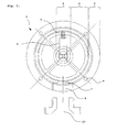
- FIG. 1 shows a valve member 1 in longitudinal view.
- the valve member 1 includes a valve housing 2 and an inner body 3.
- a coupling device 5 is arranged, which in a arranged on the inner body 3 driver. 6 reversibly engaged and disengaged.
- Both the inner body 3 as well as the valve housing 2 have passage openings. 7 or 8, which by rotation of the inner body 3 in at least partial overlap can be brought.
- the passage openings 7 and 8 lead into a sequence 19, which, for example, to a Consumer is connected.
- holes 9 are arranged in an outer area of the Valve housing 2 arranged. Through these holes 9 more valve members 1 can be added and, for example, with a threaded rod (not shown) are tightly clamped.
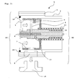
- FIG. 2 shows a side view of the valve member 1 from FIG. 1 on average.
- the flow direction of a medium flowing through is exemplified by arrows.
- the valve member has via a first connection side A1 and a second connection side A2, to which further valve members 1 or not shown here Connection or end parts can be attached (see Figure 3).
- connection sides can guarantee a dense Connection to other components sealant 10, for example O-rings can be provided.
- the interaction of drivers 6 and coupling device 5 can be seen in this side section; see also Figures 4 and 6.
- the inner body 3 is in the embodiment axially displaceable against a clamping means 11, e.g. a spring stored.
- a return means 12 In the embodiment is for engaging and disengaging the coupling device 5 a Longitudinal movement of the axis 4 necessary.
- the return means 12 may be an automatic return of the axis 4 in a starting position be effected.
- the axis 4 is in the embodiment modular from concentrically arranged elements constructed, which secured against rotation by a screw 15 are connected. This can be an individual setting if necessary the adjustment of individual valve members causes become.
- an angle ⁇ defined to which the coupling devices 5 of two valve members 1 against each other are arranged twisted In the case of a square connector the axes 4 of two valve members 1 can Angle ⁇ of 90 ° or a multiple of this angle incl. 0 °, ie 0 °, 90 ° and 180 ° are effected.
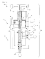
- FIG. 3 schematically shows a multi-way valve arrangement M, however, for the sake of clarity only with a valve member 1, as shown in Figure 2. Also included the multi-way valve assembly, a connection part 13 and a termination part 14.
- the axis 4 is via a plug connection Inner and outer polygonal areas composed.
- a postioning device 16 is provided by means of which the axis 4 can be rotated.
- a positioning device 17 provided by means of which the axis. 4 can be moved in the longitudinal direction.
- Eccentric 18 provided by means of which the rotational movement the positioning device 17 in a longitudinal movement of the axis. 4 transforms.
- Figure 4 shows the various relative positions of the coupling device 5 and driver 6 to each other.
- position P1 is no coupling between driver 6 and coupling device 5 possible; this corresponds to the starting position P1 of a valve member.
- the coupling device 5 By longitudinal movement of the axle, the coupling device 5 shifted so that a capture position P2 set is, in which the driver 6 with an extension of the coupling device 5 reached and possibly rotated in one direction can be.
- the driver 6 is so in the coupling device. 5 arranged that a rotation of the driver 6 in both Directions is effected.
- the method for adjusting a valve member 1 is explained stepwise in FIG.
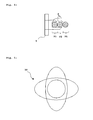
- FIG. 5 shows an eccentric 18 in plan view, which is advantageous on a positioning device 17 for longitudinal displacement the axis 4 is used. This allows a longitudinal movement the positioning device 17 and resulting leaks be avoided.
- the eccentric 18th In particular, it may be both an ellipsoidal device as well as a circular but eccentric on the positioning device 17 stored device act.
- the return means 12 is provided. In a majority Valve members 1, it is particularly advantageous only at the end cover 14 directly adjacent valve member 1 a to provide such return means 12.
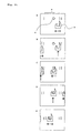
- Figure 6 shows stepwise the method for setting a Valve member 1.
- Figure 6A shows driver 6 and coupling device 5 in the initial position P1. In the starting position P1 the arranged on the axis 4 coupling device 5 at least in the angular range W rotatable without the driver. 6 is reached.
- Figure 6B shows driver 6 and coupling device 5 in a catching position P2.
- the catching position of the coupling device 5 is set by longitudinal movement of the axis. 4
- the catching position is set in an end point the angle range W, which the adjustment of the valve member 1 corresponds.
- FIG. 6C shows the approach of the coupling device 5 to the driver 6. Is the driver 6 reached, By longitudinal displacement of the axis 4, the adjustment position P3 set ( Figure 6D). In this position is one Adjustability of the driver 6 in both directions within the entire angular range W ensured ( Figure 6E).
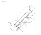
- FIG. 7 shows schematically a possible arrangement of actuating means, Here coupling devices 5 on an axis. 4
- the coupling devices 5 are compatible with drivers 6 individual valve members along the axis 4, arranged in the Embodiment each offset by an angle ⁇ of 90 °.
- the displacement angle of the actuating means on different way to be any: the actuating means can be, for example, fixedly arranged on the axis 4, wherein the Displacement angle of the individual actuating means on the joining the axis 4 is effected from segments, e.g. with a Polygonal system.
- the actuating means adjustable on the Arrange axis for example. By means of a particular stepless Screwing the actuating means on the axis 4.
- several actuating means are not staggered if it is desired that these are operated simultaneously.
Landscapes
- Engineering & Computer Science (AREA)
- General Engineering & Computer Science (AREA)
- Mechanical Engineering (AREA)
- Multiple-Way Valves (AREA)
- External Artificial Organs (AREA)
- Fluid-Pressure Circuits (AREA)
Priority Applications (4)
| Application Number | Priority Date | Filing Date | Title |
|---|---|---|---|
| EP03405670A EP1515073B1 (fr) | 2003-09-12 | 2003-09-12 | Vanne à voies multiples |
| DE50307470T DE50307470D1 (de) | 2003-09-12 | 2003-09-12 | Mehrwege-Ventilanordnung |
| AT03405670T ATE364808T1 (de) | 2003-09-12 | 2003-09-12 | Mehrwege-ventilanordnung |
| PCT/EP2004/008016 WO2005028933A1 (fr) | 2003-09-12 | 2004-07-17 | Systeme de soupapes a voies multiples |
Applications Claiming Priority (1)
| Application Number | Priority Date | Filing Date | Title |
|---|---|---|---|
| EP03405670A EP1515073B1 (fr) | 2003-09-12 | 2003-09-12 | Vanne à voies multiples |
Publications (2)
| Publication Number | Publication Date |
|---|---|
| EP1515073A1 true EP1515073A1 (fr) | 2005-03-16 |
| EP1515073B1 EP1515073B1 (fr) | 2007-06-13 |
Family
ID=34130416
Family Applications (1)
| Application Number | Title | Priority Date | Filing Date |
|---|---|---|---|
| EP03405670A Expired - Lifetime EP1515073B1 (fr) | 2003-09-12 | 2003-09-12 | Vanne à voies multiples |
Country Status (4)
| Country | Link |
|---|---|
| EP (1) | EP1515073B1 (fr) |
| AT (1) | ATE364808T1 (fr) |
| DE (1) | DE50307470D1 (fr) |
| WO (1) | WO2005028933A1 (fr) |
Cited By (1)
| Publication number | Priority date | Publication date | Assignee | Title |
|---|---|---|---|---|
| WO2020057743A1 (fr) | 2018-09-20 | 2020-03-26 | Climeo Ag | Agencements de soupapes à plusieurs voies pour réguler le débit d'un fluide |
Citations (4)
| Publication number | Priority date | Publication date | Assignee | Title |
|---|---|---|---|---|
| US4357952A (en) * | 1979-08-29 | 1982-11-09 | Teledyne Adams | Tubular valve device and method of assembly |
| DE3118471A1 (de) * | 1981-05-09 | 1982-11-25 | Schmidt Reuter Ingenieurgesellschaft mbH & Co KG, 5000 Köln | Fluidverteiler |
| US20010011557A1 (en) * | 1998-07-23 | 2001-08-09 | Pecci Gene L. | Backwash valve |
| US20030000585A1 (en) * | 2001-06-27 | 2003-01-02 | Lefco Cps, Inc. | Modular vacuum and low pressure valve assembly |
-
2003
- 2003-09-12 DE DE50307470T patent/DE50307470D1/de not_active Expired - Lifetime
- 2003-09-12 EP EP03405670A patent/EP1515073B1/fr not_active Expired - Lifetime
- 2003-09-12 AT AT03405670T patent/ATE364808T1/de active
-
2004
- 2004-07-17 WO PCT/EP2004/008016 patent/WO2005028933A1/fr not_active Ceased
Patent Citations (4)
| Publication number | Priority date | Publication date | Assignee | Title |
|---|---|---|---|---|
| US4357952A (en) * | 1979-08-29 | 1982-11-09 | Teledyne Adams | Tubular valve device and method of assembly |
| DE3118471A1 (de) * | 1981-05-09 | 1982-11-25 | Schmidt Reuter Ingenieurgesellschaft mbH & Co KG, 5000 Köln | Fluidverteiler |
| US20010011557A1 (en) * | 1998-07-23 | 2001-08-09 | Pecci Gene L. | Backwash valve |
| US20030000585A1 (en) * | 2001-06-27 | 2003-01-02 | Lefco Cps, Inc. | Modular vacuum and low pressure valve assembly |
Non-Patent Citations (1)
| Title |
|---|
| DATABASE WPI Section PQ Week 198248, Derwent World Patents Index; Class Q66, AN 1982-A3345J, XP002268604 * |
Cited By (1)
| Publication number | Priority date | Publication date | Assignee | Title |
|---|---|---|---|---|
| WO2020057743A1 (fr) | 2018-09-20 | 2020-03-26 | Climeo Ag | Agencements de soupapes à plusieurs voies pour réguler le débit d'un fluide |
Also Published As
| Publication number | Publication date |
|---|---|
| ATE364808T1 (de) | 2007-07-15 |
| DE50307470D1 (de) | 2007-07-26 |
| EP1515073B1 (fr) | 2007-06-13 |
| WO2005028933A1 (fr) | 2005-03-31 |
Similar Documents
| Publication | Publication Date | Title |
|---|---|---|
| EP1943441B1 (fr) | Activateur comprenant un mecanisme de reduction pour un element d'activation permettant de reguler le debit d'un gaz ou d'un fluide | |
| EP2271969B1 (fr) | Système de robinetterie permettant de réguler le débit ou la différence de pression | |
| DE2953331C1 (de) | Steuerungs- und Absperrventil fuer stroemende Medien | |
| DE60019481T2 (de) | Klappeanordnung und Fluidumlauf- und Verteilergerät mit einer solchen Anordnung | |
| EP3280934B1 (fr) | Agencement avec vanne et actionneur | |
| EP2932142B1 (fr) | Vanne mélangeuse multivoie et procédé de commande temporelle d'une vanne mélangeuse multivoie | |
| DE68904757T2 (de) | Kugelventil. | |
| EP0638154A1 (fr) | Soupape pour la regulation du debit d'un fluide s'ecoulant sous pression. | |
| DE60008954T2 (de) | Sicherheitgasventilanordnung für einen Kochherd | |
| EP1355095A2 (fr) | Vanne mélangeur à quatre voies | |
| EP2183509A2 (fr) | Dispositif de restriction de la section transversale libre d'une conduite de vapeur ou analogue | |
| EP1859329A1 (fr) | Regulateur de debit | |
| DE19834575A1 (de) | Drehschieberventil | |
| EP1515073B1 (fr) | Vanne à voies multiples | |
| DE102012006624A1 (de) | Drosselvorrichtung | |
| DE102007013505A1 (de) | Armaturenkombination zur Regelung der Durchflussmenge oder des Differenzdruckes | |
| EP0791772A2 (fr) | Soupape à trois voies pour jonction hydraulique | |
| AT412991B (de) | Verteilerventil | |
| DE3118471C2 (fr) | ||
| EP0898100A2 (fr) | Vanne-mélangeur à voies multiples | |
| DE102005011947B3 (de) | Durchflussmengenregler | |
| CH691823A5 (de) | Membran-Ventil. | |
| DE3124790A1 (de) | Rohranschlussvorrichtung, insbesondere fuer zentralheizungssysteme | |
| DE3107929A1 (de) | "anschlussnippel fuer ein ventil, insbesondere heizkoerperventil" | |
| EP2212599A2 (fr) | Robinet à bille |
Legal Events
| Date | Code | Title | Description |
|---|---|---|---|
| PUAI | Public reference made under article 153(3) epc to a published international application that has entered the european phase |
Free format text: ORIGINAL CODE: 0009012 |
|
| AK | Designated contracting states |
Kind code of ref document: A1 Designated state(s): AT BE BG CH CY CZ DE DK EE ES FI FR GB GR HU IE IT LI LU MC NL PT RO SE SI SK TR |
|
| AX | Request for extension of the european patent |
Extension state: AL LT LV MK |
|
| 17P | Request for examination filed |
Effective date: 20050804 |
|
| AKX | Designation fees paid |
Designated state(s): AT BE BG CH CY CZ DE DK EE ES FI FR GB GR HU IE IT LI LU MC NL PT RO SE SI SK TR |
|
| GRAP | Despatch of communication of intention to grant a patent |
Free format text: ORIGINAL CODE: EPIDOSNIGR1 |
|
| 17Q | First examination report despatched |
Effective date: 20060209 |
|
| GRAS | Grant fee paid |
Free format text: ORIGINAL CODE: EPIDOSNIGR3 |
|
| GRAA | (expected) grant |
Free format text: ORIGINAL CODE: 0009210 |
|
| AK | Designated contracting states |
Kind code of ref document: B1 Designated state(s): AT BE BG CH CY CZ DE DK EE ES FI FR GB GR HU IE IT LI LU MC NL PT RO SE SI SK TR |
|
| REG | Reference to a national code |
Ref country code: GB Ref legal event code: FG4D Free format text: NOT ENGLISH |
|
| REG | Reference to a national code |
Ref country code: CH Ref legal event code: EP |
|
| REG | Reference to a national code |
Ref country code: IE Ref legal event code: FG4D Free format text: LANGUAGE OF EP DOCUMENT: GERMAN |
|
| REG | Reference to a national code |
Ref country code: CH Ref legal event code: NV Representative=s name: HEPP, WENGER & RYFFEL AG |
|
| REF | Corresponds to: |
Ref document number: 50307470 Country of ref document: DE Date of ref document: 20070726 Kind code of ref document: P |
|
| PG25 | Lapsed in a contracting state [announced via postgrant information from national office to epo] |
Ref country code: SE Free format text: LAPSE BECAUSE OF FAILURE TO SUBMIT A TRANSLATION OF THE DESCRIPTION OR TO PAY THE FEE WITHIN THE PRESCRIBED TIME-LIMIT Effective date: 20070913 |
|
| NLV1 | Nl: lapsed or annulled due to failure to fulfill the requirements of art. 29p and 29m of the patents act | ||
| GBV | Gb: ep patent (uk) treated as always having been void in accordance with gb section 77(7)/1977 [no translation filed] |
Effective date: 20070613 |
|
| REG | Reference to a national code |
Ref country code: IE Ref legal event code: FD4D |
|
| PG25 | Lapsed in a contracting state [announced via postgrant information from national office to epo] |
Ref country code: NL Free format text: LAPSE BECAUSE OF FAILURE TO SUBMIT A TRANSLATION OF THE DESCRIPTION OR TO PAY THE FEE WITHIN THE PRESCRIBED TIME-LIMIT Effective date: 20070613 Ref country code: IE Free format text: LAPSE BECAUSE OF FAILURE TO SUBMIT A TRANSLATION OF THE DESCRIPTION OR TO PAY THE FEE WITHIN THE PRESCRIBED TIME-LIMIT Effective date: 20070613 Ref country code: PT Free format text: LAPSE BECAUSE OF FAILURE TO SUBMIT A TRANSLATION OF THE DESCRIPTION OR TO PAY THE FEE WITHIN THE PRESCRIBED TIME-LIMIT Effective date: 20071113 Ref country code: SI Free format text: LAPSE BECAUSE OF FAILURE TO SUBMIT A TRANSLATION OF THE DESCRIPTION OR TO PAY THE FEE WITHIN THE PRESCRIBED TIME-LIMIT Effective date: 20070613 Ref country code: ES Free format text: LAPSE BECAUSE OF FAILURE TO SUBMIT A TRANSLATION OF THE DESCRIPTION OR TO PAY THE FEE WITHIN THE PRESCRIBED TIME-LIMIT Effective date: 20070924 Ref country code: CZ Free format text: LAPSE BECAUSE OF FAILURE TO SUBMIT A TRANSLATION OF THE DESCRIPTION OR TO PAY THE FEE WITHIN THE PRESCRIBED TIME-LIMIT Effective date: 20070613 Ref country code: BG Free format text: LAPSE BECAUSE OF FAILURE TO SUBMIT A TRANSLATION OF THE DESCRIPTION OR TO PAY THE FEE WITHIN THE PRESCRIBED TIME-LIMIT Effective date: 20070913 |
|
| EN | Fr: translation not filed | ||
| PG25 | Lapsed in a contracting state [announced via postgrant information from national office to epo] |
Ref country code: SK Free format text: LAPSE BECAUSE OF FAILURE TO SUBMIT A TRANSLATION OF THE DESCRIPTION OR TO PAY THE FEE WITHIN THE PRESCRIBED TIME-LIMIT Effective date: 20070613 |
|
| BERE | Be: lapsed |
Owner name: DANIEL BURKHALTER (DIPL. ING.) Effective date: 20070930 |
|
| PLBE | No opposition filed within time limit |
Free format text: ORIGINAL CODE: 0009261 |
|
| STAA | Information on the status of an ep patent application or granted ep patent |
Free format text: STATUS: NO OPPOSITION FILED WITHIN TIME LIMIT |
|
| PG25 | Lapsed in a contracting state [announced via postgrant information from national office to epo] |
Ref country code: GR Free format text: LAPSE BECAUSE OF FAILURE TO SUBMIT A TRANSLATION OF THE DESCRIPTION OR TO PAY THE FEE WITHIN THE PRESCRIBED TIME-LIMIT Effective date: 20070914 Ref country code: DK Free format text: LAPSE BECAUSE OF FAILURE TO SUBMIT A TRANSLATION OF THE DESCRIPTION OR TO PAY THE FEE WITHIN THE PRESCRIBED TIME-LIMIT Effective date: 20070613 Ref country code: IT Free format text: LAPSE BECAUSE OF FAILURE TO SUBMIT A TRANSLATION OF THE DESCRIPTION OR TO PAY THE FEE WITHIN THE PRESCRIBED TIME-LIMIT Effective date: 20070613 Ref country code: MC Free format text: LAPSE BECAUSE OF NON-PAYMENT OF DUE FEES Effective date: 20070930 Ref country code: GB Free format text: LAPSE BECAUSE OF FAILURE TO SUBMIT A TRANSLATION OF THE DESCRIPTION OR TO PAY THE FEE WITHIN THE PRESCRIBED TIME-LIMIT Effective date: 20070613 |
|
| 26N | No opposition filed |
Effective date: 20080314 |
|
| PG25 | Lapsed in a contracting state [announced via postgrant information from national office to epo] |
Ref country code: RO Free format text: LAPSE BECAUSE OF FAILURE TO SUBMIT A TRANSLATION OF THE DESCRIPTION OR TO PAY THE FEE WITHIN THE PRESCRIBED TIME-LIMIT Effective date: 20070613 |
|
| PG25 | Lapsed in a contracting state [announced via postgrant information from national office to epo] |
Ref country code: FR Free format text: LAPSE BECAUSE OF FAILURE TO SUBMIT A TRANSLATION OF THE DESCRIPTION OR TO PAY THE FEE WITHIN THE PRESCRIBED TIME-LIMIT Effective date: 20080208 |
|
| PG25 | Lapsed in a contracting state [announced via postgrant information from national office to epo] |
Ref country code: BE Free format text: LAPSE BECAUSE OF NON-PAYMENT OF DUE FEES Effective date: 20070930 |
|
| PG25 | Lapsed in a contracting state [announced via postgrant information from national office to epo] |
Ref country code: EE Free format text: LAPSE BECAUSE OF FAILURE TO SUBMIT A TRANSLATION OF THE DESCRIPTION OR TO PAY THE FEE WITHIN THE PRESCRIBED TIME-LIMIT Effective date: 20070613 |
|
| PG25 | Lapsed in a contracting state [announced via postgrant information from national office to epo] |
Ref country code: FI Free format text: LAPSE BECAUSE OF FAILURE TO SUBMIT A TRANSLATION OF THE DESCRIPTION OR TO PAY THE FEE WITHIN THE PRESCRIBED TIME-LIMIT Effective date: 20070613 |
|
| PG25 | Lapsed in a contracting state [announced via postgrant information from national office to epo] |
Ref country code: CY Free format text: LAPSE BECAUSE OF FAILURE TO SUBMIT A TRANSLATION OF THE DESCRIPTION OR TO PAY THE FEE WITHIN THE PRESCRIBED TIME-LIMIT Effective date: 20070613 |
|
| PG25 | Lapsed in a contracting state [announced via postgrant information from national office to epo] |
Ref country code: LU Free format text: LAPSE BECAUSE OF NON-PAYMENT OF DUE FEES Effective date: 20070912 |
|
| PG25 | Lapsed in a contracting state [announced via postgrant information from national office to epo] |
Ref country code: HU Free format text: LAPSE BECAUSE OF FAILURE TO SUBMIT A TRANSLATION OF THE DESCRIPTION OR TO PAY THE FEE WITHIN THE PRESCRIBED TIME-LIMIT Effective date: 20071214 Ref country code: TR Free format text: LAPSE BECAUSE OF FAILURE TO SUBMIT A TRANSLATION OF THE DESCRIPTION OR TO PAY THE FEE WITHIN THE PRESCRIBED TIME-LIMIT Effective date: 20070613 |
|
| PGFP | Annual fee paid to national office [announced via postgrant information from national office to epo] |
Ref country code: AT Payment date: 20120829 Year of fee payment: 10 |
|
| REG | Reference to a national code |
Ref country code: AT Ref legal event code: MM01 Ref document number: 364808 Country of ref document: AT Kind code of ref document: T Effective date: 20130912 |
|
| PG25 | Lapsed in a contracting state [announced via postgrant information from national office to epo] |
Ref country code: AT Free format text: LAPSE BECAUSE OF NON-PAYMENT OF DUE FEES Effective date: 20130912 |
|
| REG | Reference to a national code |
Ref country code: DE Ref legal event code: R082 Ref document number: 50307470 Country of ref document: DE Representative=s name: HAUCK PATENTANWALTSPARTNERSCHAFT MBB, DE |
|
| REG | Reference to a national code |
Ref country code: DE Ref legal event code: R082 Ref document number: 50307470 Country of ref document: DE Representative=s name: HAUCK PATENT- UND RECHTSANWAELTE, DE |
|
| PGFP | Annual fee paid to national office [announced via postgrant information from national office to epo] |
Ref country code: DE Payment date: 20220816 Year of fee payment: 20 |
|
| PGFP | Annual fee paid to national office [announced via postgrant information from national office to epo] |
Ref country code: CH Payment date: 20221130 Year of fee payment: 20 |
|
| REG | Reference to a national code |
Ref country code: DE Ref legal event code: R071 Ref document number: 50307470 Country of ref document: DE |
|
| REG | Reference to a national code |
Ref country code: CH Ref legal event code: PL |