EP1515064A1 - Electromagnetic shock absorber - Google Patents
Electromagnetic shock absorber Download PDFInfo
- Publication number
- EP1515064A1 EP1515064A1 EP03730663A EP03730663A EP1515064A1 EP 1515064 A1 EP1515064 A1 EP 1515064A1 EP 03730663 A EP03730663 A EP 03730663A EP 03730663 A EP03730663 A EP 03730663A EP 1515064 A1 EP1515064 A1 EP 1515064A1
- Authority
- EP
- European Patent Office
- Prior art keywords
- shock absorber
- motor
- rotary
- section
- electromagnetic
- Prior art date
- Legal status (The legal status is an assumption and is not a legal conclusion. Google has not performed a legal analysis and makes no representation as to the accuracy of the status listed.)
- Granted
Links
- 230000035939 shock Effects 0.000 title claims abstract description 90
- 239000006096 absorbing agent Substances 0.000 title claims abstract description 89
- 230000033001 locomotion Effects 0.000 claims abstract description 87
- 230000007246 mechanism Effects 0.000 claims abstract description 26
- 230000005540 biological transmission Effects 0.000 claims abstract description 12
- 230000004044 response Effects 0.000 claims abstract description 7
- 238000013016 damping Methods 0.000 description 27
- 230000008878 coupling Effects 0.000 description 22
- 238000010168 coupling process Methods 0.000 description 22
- 238000005859 coupling reaction Methods 0.000 description 22
- 239000000725 suspension Substances 0.000 description 12
- 230000001133 acceleration Effects 0.000 description 7
- 230000008859 change Effects 0.000 description 5
- 230000003111 delayed effect Effects 0.000 description 5
- 239000000463 material Substances 0.000 description 4
- 230000008901 benefit Effects 0.000 description 3
- 230000005489 elastic deformation Effects 0.000 description 3
- 230000006870 function Effects 0.000 description 3
- 230000008439 repair process Effects 0.000 description 3
- 125000006850 spacer group Chemical group 0.000 description 3
- 230000000694 effects Effects 0.000 description 2
- 230000014759 maintenance of location Effects 0.000 description 2
- 238000010521 absorption reaction Methods 0.000 description 1
- 230000015556 catabolic process Effects 0.000 description 1
- 239000011248 coating agent Substances 0.000 description 1
- 238000000576 coating method Methods 0.000 description 1
- 230000006835 compression Effects 0.000 description 1
- 238000007906 compression Methods 0.000 description 1
- 230000001934 delay Effects 0.000 description 1
- 238000013461 design Methods 0.000 description 1
- 230000006866 deterioration Effects 0.000 description 1
- 238000010586 diagram Methods 0.000 description 1
- 230000006872 improvement Effects 0.000 description 1
- 230000006698 induction Effects 0.000 description 1
- 238000003780 insertion Methods 0.000 description 1
- 230000037431 insertion Effects 0.000 description 1
- 238000009434 installation Methods 0.000 description 1
- 238000009413 insulation Methods 0.000 description 1
- 238000004519 manufacturing process Methods 0.000 description 1
- 230000013011 mating Effects 0.000 description 1
- 238000000034 method Methods 0.000 description 1
- 230000004048 modification Effects 0.000 description 1
- 238000012986 modification Methods 0.000 description 1
- 230000008569 process Effects 0.000 description 1
- 238000012545 processing Methods 0.000 description 1
- 230000000452 restraining effect Effects 0.000 description 1
- 239000000126 substance Substances 0.000 description 1
- 229920003002 synthetic resin Polymers 0.000 description 1
- 239000000057 synthetic resin Substances 0.000 description 1
Images


Classifications
-
- F—MECHANICAL ENGINEERING; LIGHTING; HEATING; WEAPONS; BLASTING
- F16—ENGINEERING ELEMENTS AND UNITS; GENERAL MEASURES FOR PRODUCING AND MAINTAINING EFFECTIVE FUNCTIONING OF MACHINES OR INSTALLATIONS; THERMAL INSULATION IN GENERAL
- F16F—SPRINGS; SHOCK-ABSORBERS; MEANS FOR DAMPING VIBRATION
- F16F15/00—Suppression of vibrations in systems; Means or arrangements for avoiding or reducing out-of-balance forces, e.g. due to motion
- F16F15/02—Suppression of vibrations of non-rotating, e.g. reciprocating systems; Suppression of vibrations of rotating systems by use of members not moving with the rotating systems
- F16F15/03—Suppression of vibrations of non-rotating, e.g. reciprocating systems; Suppression of vibrations of rotating systems by use of members not moving with the rotating systems using magnetic or electromagnetic means
-
- F—MECHANICAL ENGINEERING; LIGHTING; HEATING; WEAPONS; BLASTING
- F16—ENGINEERING ELEMENTS AND UNITS; GENERAL MEASURES FOR PRODUCING AND MAINTAINING EFFECTIVE FUNCTIONING OF MACHINES OR INSTALLATIONS; THERMAL INSULATION IN GENERAL
- F16F—SPRINGS; SHOCK-ABSORBERS; MEANS FOR DAMPING VIBRATION
- F16F2232/00—Nature of movement
- F16F2232/06—Translation-to-rotary conversion
Definitions
- the present invention relates to an electromagnetic shock absorber which converts telescopic motion of a shock absorber body into rotary motion of a motor utilizing a ball screw mechanism and damps vibration utilizing electromagnetic resistance generated by the motor.
- a suspension unit for a vehicle in which a hydraulic shock absorber is arranged, in parallel with a suspension spring, between a car body and an axle is well known.
- Japanese Patent Laid-Open Publication No. 5-44758A has disclosed a suspension unit in which magnet coils are built in a hydraulic shock absorber.
- coils are attached to a cylinder of the hydraulic shock absorber and magnets are attached to a piston rod, respectively, and an electric current is applied to the coils, thereby generating driving force (electromagnetic force) along the direction of a stroke of the piston rod so as to control the quantity of telescopic motion of the suspension unit according to the traveling condition of a vehicle.
- Such an electromagnetic shock absorber which does not require a hydraulic pressure, an air pressure, a power source, or the like is under study.
- Such an electromagnetic shock absorber is basically constituted as shown in an exemplified model of FIG. 6.
- a motor 50 is supported by a supporting frame 30, and there is provided a traveling frame 40 which is guided in such a manner that the traveling frame 40 can freely slide with respect to the supporting frame 30.
- a traveling frame 40 which is guided in such a manner that the traveling frame 40 can freely slide with respect to the supporting frame 30.
- the ball nut 47 is attached to the above-mentioned traveling frame 40, and the screw shaft 46 to be spirally engaged with the ball nut 47 is coaxially connected with a rotary shaft 51 of the above-mentioned motor 50 through a coupling 55.
- the supporting frame 30 has an upper bracket 31, a lower bracket 32, and an intermediate bracket 33 which is located between the upper bracket 31 and the lower bracket 32.
- the supporting frame 30 is constituted in such a manner that these brackets are connected with each other by means of a plurality of connecting rods 34.
- the above-mentioned screw shaft 46 is rotatably supported, by a bearing 35 installed at the intermediate bracket 33, in such a manner that the screw shaft 46 goes through the bearing 35.
- the traveling frame 40 has an upper bracket 41, a lower bracket 42, and a plurality of guide rods 43 which connect these brackets 41 and 42.
- the guide rods 43 of the traveling frame 40 slidably go through the lower bracket 32 of the above-mentioned supporting frame 30, whereby the guide rods 43 guide the traveling frame 40 in such a manner that the traveling frame 40 can slide in parallel with the screw shaft 46.
- the above-mentioned ball nut 47 is attached to the upper bracket 41, and a large number of balls are arranged along a thread groove inside the ball nut 47 although these balls are not shown in the drawing.
- the screw shaft 46 is spirally engaged with the ball nut 47 through the large number of balls.
- the electromagnetic shock absorber is interposed between a car body and an axle, for example, and is utilized as a suspension of the car, a mounting bracket 36 of the supporting frame 30 which is located above the motor 50 and at an upper end of the electromagnetic shock absorber will be connected on the side of the car body, and a mounting eye 44 which is provided at the lower bracket 42 of the traveling frame 40 at a lower end of the electromagnetic shock absorber will be connected on the axle side.
- the rotary motion of the screw shaft 46 is transmitted, as rotary motion of a rotary shaft 51 in the direction of an arrow Y, through the coupling 55 attached to an upper end of the screw shaft 46, thereby rotating the motor 50.
- the motor 50 for example permanent magnets are arranged at a rotor of the motor 50, and coils of a stator of the respective magnetic poles short-circuit directly to each other or the coils are connected via a control circuit so that desired electromagnetic force can be obtained.
- a control circuit so that desired electromagnetic force can be obtained.
- Electromagnetic torque which becomes resistance against the rotations of the rotary shaft 51 restrains the rotations of the above-mentioned screw shaft 46. After all, the torque operates as resistance to restrain linear motion of the ball nut 47 of the ball screw mechanism 45, that is, as damping force against the vibration which puts into the electromagnetic shock absorber.
- the damping force generated by the electromagnetic shock absorber namely, the resistance (load) against the telescopic motion is approximately the sum total of the moment of inertia of the rotor of the motor, the moment of inertia of the screw shaft, and the electromagnetic resistance generated by the motor. Because angular acceleration of the rotary shaft of the motor is proportional to acceleration of the telescopic motion of the shock absorber, the moment of inertia of the rotor is proportional to the acceleration of the telescopic motion of the shock absorber.
- the moment of inertia of the rotor is proportional to the acceleration of the telescopic motion of the shock absorber and therefore the damping force which is not based on the electromagnetic force of the motor is generated against the force in an axial direction of the shock absorber which is input from the surface of a road into the shock absorber.
- greater damping force namely, resistance against vibration will be generated by the rotor accordingly.
- This exceedingly high damping force does not absorb the vibration and the vibration is directly transmitted to the side of a car body as it is.
- the damping force due to the moment of inertia of the rotor of the motor always arises prior to generation of the damping force which depends on the electromagnetic force of the motor.
- the moment of inertia of the rotor is relatively great as described above, if it is possible to exclude or restrain the influence which the moment of inertia of the rotor exercises on the damping force, vibrational absorption capacity will be increased accordingly. This makes vehicles more comfortable to drive.
- the electromagnetic shock absorber referring to the electromagnetic shock absorber's controllability over damping force, it is difficult to control the damping force which arises resulting from the moment of inertia of the rotor of the motor closely relevant to the acceleration of telescopic motion of the above-mentioned shock absorber. Thus, it is preferable that the above-mentioned moment of inertia is less influential.
- the traveling frame 40 travels and the ball nut 47 of the ball screw mechanism 45 makes linear motion at the same speed as the traveling speed of the traveling frame 40.
- the screw shaft 46 also rotates at a speed in proportion to the speed of the linear motion, and the rotary shaft 51 of the motor 50 also rotates at the same speed as that of the screw shaft 46.
- the motor 50 is more expensive than other parts of the electromagnetic shock absorber. Therefore, it is desirable to make every effort to prevent the motor 50 from being damaged.
- An advantage of the present invention is to provide an electromagnetic shock absorber which is capable of restraining the influence that moment of inertia of a rotor of a motor exercises on damping force and which is capable of making vehicles more comfortable to drive and promptly controlling the damping force according to the traveling conditions in the case that the shock absorber is applied to the suspension of a vehicle.
- a further advantage of the present invention is to provide an electromagnetic shock absorber being capable of preventing a motor from being subjected to damage, as much as possible, which may arise resulting from calorification of the motor and enabling repair of breakdown at a low cost.
- the electromagnetic shock absorber comprises: a shock absorber body which makes telescopic motion in response to an input from outside; a ball screw mechanism which is arranged at the shock absorber body, converts the telescopic motion into rotary motion, and is composed of a ball nut and a screw shaft; a motor which is provided at the shock absorber body and generates electromagnetic resistance to oppose against rotations to be input into a rotary shaft of the motor; and a power transmitting section having an elastic body which transmits rotary motion of the ball screw mechanism to the rotary shaft of the motor and also shifts a transmission phase of the rotary motion when rotation torque of the rotary motion is changed.
- the power transmitting section includes a torsion bar.
- the torsion bar is constituted such that the torsion bar will break if the above-mentioned rotary torque to be transmitted is greater than a prescribed value.
- the power transmitting section is composed of a drive section and a driven section and the elastic body is provided on a torque transmission surface which intervenes between the drive section and the driven section.
- projections provided at the power transmitting section are constituted such that the projections will break if the above-mentioned rotation torque to be transmitted is greater than a prescribed value.
- the above-mentioned prescribed value corresponds to a torque value at a time when a rotational speed of the motor to be rotated due to the rotation torque reaches an allowable rotational speed.
- the vehicle when the telescopic motion of the shock absorber body is transmitted to the rotary shaft of the motor as the rotary motion, a time-lag of phase arises and it is possible to delay the generation of great damping force which arises resulting from the moment of inertia of the rotor in the motor or reduce the great damping force.
- the electromagnetic shock absorber in the case of applying the electromagnetic shock absorber to a suspension of a vehicle, the vehicle can be made more comfortable to drive and damping force can promptly be controlled according to the traveling conditions.
- FIG. 1 is a sectional view showing an electromagnetic shock absorber according to a first embodiment.
- a shock absorber body 1 has an external cylinder 3 and an internal cylinder 6 which is coaxially inserted in the external cylinder 3 in such a manner that the internal cylinder 6 can freely slide in the external cylinder 3.
- a sliding position of the internal cylinder 6 in the external cylinder 3 is located at a lower part of the external cylinder 3 which is omitted from the drawing.
- a cylindrical case 7 is coaxially connected at an upper part of the external cylinder 3, and a motor 10 housed in a housing 8 is installed at an upper part of the case 7.
- a ball nut 16 which constitutes a ball screw mechanism 15 is installed.
- a screw shaft 17 to be spirally engaged with the ball nut 16 extends to the inside of the internal cylinder 6.
- a thread groove of the screw shaft 17 is guided and spirally engaged with a large number of balls which are arranged on a thread groove in the ball nut 16.
- the ball screw mechanism 15 has a function of converting the linear motion into the rotary motion very smoothly and without resistance by spiral engagement of the large number of balls and the thread groove, and thus the ball screw mechanism 15 is the most preferable one.
- a mechanism to convert the linear motion into the rotary motion is not always restricted to the ball screw mechanism 15.
- the ball screw mechanism 15 will not be an obstacle to adoption of another mechanism which has a similar effect.
- An upper end of the screw shaft 17 which goes through the ball nut 16 is supported by a ball bearing 9 which is installed inside a lower end of the case 7 through a retention member 8 in such a manner that the screw shaft 17 can freely rotate and does not fall off downward.
- annular cushion member 5 is installed on a lower surface of the retention member 8.
- the annular cushion member 5 elastically meets with the internal cylinder 6 at the uppermost position so that the shock is cushioned and also a further upward movement of the internal cylinder 6 is stopped.
- a torsion bar 13 is first arranged as a power transmitting section at a case shaft center section in the case 7. An upper end of the screw shaft 17 is inserted at a lower end of the torsion bar 13 and fixed by a key or the like so as to prevent mutual rotations. An upper end of the torsion bar 13 is coaxially connected with a rotary shaft 11 of the motor 10 by a coupling 14.
- a bracket not shown in the drawing is installed above the external cylinder 3 and at an upper end of the housing 8 in which the motor 10 is housed.
- a bracket is also installed at a lower end of the internal cylinder 6. Between the brackets, using the upper bracket, connection with the car body side is made, on the other hand, using the lower bracket, connection with the axle side is made.
- coils of respective magnetic poles are electrically connected to each other or connected via a control circuit.
- a control circuit When rotary torque is transmitted to the rotary shaft 11 of the motor 10, induced electromotive force occurs to the coils and electromagnetic force which opposes against an input of rotations of the motor is always generated.
- This electromagnetic resistance restrains rotary motion of the screw shaft 17, and after all resistance is applied to telescopic motion of the shock absorber body 1 which is linear motion of the internal cylinder 6 so as to generate damping force by the electromagnetic shock absorber.
- the motor 10 functions as a source of the outbreak of the electromagnetic resistance and various motors, such as a direct current motor, an alternating current motor, or an induction motor, are applicable.
- a stator to which a plurality of permanent magnets for generating magnetic fields are attached and a rotor to which coils constituting a plurality of magnetic poles are attached are arranged in the motor. Coils of respective magnetic poles are connected to each other and thus the rotary shaft of the motor is rotated and the rotor rotates. Whichever direction the motor is rotated when the coils generate induced electromotive force by going across magnetic fields generated by permanent magnets, electromagnetic force which acts on the motor as resistance against rotations of the motor is generated.
- damping force which opposes against vibration or the like to be input into the electromagnetic shock absorber is generated.
- Strength of the electromagnetic force to be generated by the coils can freely and instantaneously be adjusted, for example, by switching the strength of resistance of the control circuit to be connected with coils of respective magnetic poles. Thus, it is possible to freely and promptly control the damping force which is generated according to driving status of a vehicle or the like.
- the power transmitting section is composed of the torsion bar 13, which is an elastic deformation member, and the coupling 14 which is connected with the torsion bar 13.
- the torsion bar 13 is formed in one united body by a slender, stick-type torsion bar body 13c with a smaller sectional area, a lower connecting section 13b which is provided at a lower end of the body 13c and has a sectional area larger than that of the body 13c, an opening 13a which is concentrically provided at a lower end of the connecting section 13b, and an upper connecting section 13d which is provided at an upper end of the body 13c.
- the coupling 14 has a stepped hole 14a therein and is roughly cylindrical.
- the rotary shaft 11 of the motor 10 is inserted into the stepped hole 14a from above, on the other hand, the upper connecting section 13d of the torsion bar 13 is inserted from bottom.
- a key way is provided at the rotary shaft 11 and the stepped hole 14a, respectively, and a key 12a is inserted into the key way, so that the rotary shaft 11 and the coupling 14 are connected to prevent their idle running.
- a thread hole 14b and a thread hole 14c are provided at an upper part and a lower part of a lateral surface of the coupling 14, respectively, in such a manner that these thread holes 14b and 14c go through up to the stepped hole 14a, respectively. Screws not shown in the drawing are spirally engaged with the thread holes 14b and 14c, respectively, and therefore it is possible to fix the rotary shaft 11 and the torsion bar 13 to prevent their mutual idle running.
- an upper end of the screw shaft 17 is connected to a lower end of the torsion bar 13.
- the upper end of the screw shaft 17 is inserted into the opening 13a of the torsion bar 13, and a key 12b is inserted into a key way provided on an insertion surface of the opening 13a and the screw shaft 17, so that the torsion bar 13 and the screw shaft 17 are connected to prevent their mutual idle running.
- the electromagnetic shock absorber is applied as a suspension of a vehicle
- an impact from a surface of a road such as pushing up force or vibration
- the internal cylinder 6 makes linear motion in a direction of the telescopic motion along the external cylinder 3.
- the linear motion of the ball nut 16 which moves together with the internal cylinder 6 in one united body is converted into rotary motion of the screw shaft 17 by the ball screw mechanism 15.
- the electromagnetic force operates as damping force to restrain the linear motion of the internal cylinder 6 along the external cylinder 3 and in a direction of telescopic motion, impact energy from the surface of a road is absorbed and eased, a vehicle is made more comfortable to drive, and drivability is improved.
- the torsion bar 13 when rotary force, namely, rotary torque is applied to the torsion bar 13 which is about to rotate in response to the rotary movement of the screw shaft 17 due to vibration or the like which inputs in the electromagnetic shock absorber from outside, the torsion bar 13 absorbs the rotary force and while being twisted according to the torque, the torsion bar 13 transmits the torque not only to the coupling 14, but also to the rotary shaft 11 of the motor 10.
- the torsion bar 13 transmits rotary motion of the screw shaft 17 to the rotary shaft 11 of the motor 10, it will be sufficient if the torsion bar 13 is made with materials capable of securing prescribed strength against the torque which may arise due to the screw shaft 17 or the motor 10.
- an aim of the present invention is that when the screw shaft 17 commences rotary motion or when the rotary speed changes, transmission of rotations of the screw shaft 17 to the rotary shaft 11 of the motor 10 is delayed.
- torsional rigidity of the torsion bar 13 is adjusted and a difference of the rotary speed is rendered optimal for a vehicle to which the electromagnetic shock absorber is applied.
- the torsion bar 13 will be cut when sudden force in an axial direction is applied from the surface of a road to the internal cylinder 6.
- a rotary speed of the rotary shaft 11 exceeds the allowable rotary speed of the motor 10 which may arise resulting from sudden telescopic motion of the electromagnetic shock absorber.
- the torsion bar 13 is used for the power transmitting section in consideration of facilitation in installation and fabrication.
- the present invention is directed to delay the generation of damping force due to moment of inertia of the rotor of the motor 10 by producing a difference of the rotary speed described above.
- an electromagnetic clutch may be used for the power transmitting section.
- torsion bar 13 is formed in one united body as described above, but it is not always restricted to this type. As long as it has a part which is twisted by rotary torque to be input, another configuration is acceptable.
- the coupling 14 has small moment of inertia, if possible.
- the constitution is such that a coupling 24 in which an elastic body is arranged is provided as the power transmitting section described above, whereby transmission of rotary torque is delayed, and when rotary torque which a rotary speed of the motor 10 exceeds an allowable limit speed is applied, a vulnerable section is cut and transmission of the rotary torque is stopped.
- the screw shaft 17 is directly connected with the rotary shaft 11 of the motor 10 by the coupling 24.
- the coupling 24 is composed of a pair of a drive section 25 and a driven section 26 which are constituted identically with each other and an elastic body 27 which is interposed between the drive section 25 and the driven section 26.
- a hole 22 is bored through the center of a cylindrical body 21 and a key way 22a is formed on an inner circumferential surface of the hole 22.
- the rotary shaft 11 of the motor 10 or the screw shaft 17 is inserted in the hole 22, and a key way not shown in the drawing is provided at the rotary shaft 11 and the screw shaft 17 as a mating key way of the key way 22a, respectively.
- a key 19a or 19b is inserted between the key way 22a and the key way of the rotary shaft 11 or the key way of the screw shaft 17.
- the cylindrical body 21 is connected with the rotary shaft 11 or the screw shaft 17 to prevent their idle running.
- a thread hole 22b which is bored through the hole 22 is formed on a side surface of the cylindrical body 21, and a spiral engaging stopper 22c is spirally engaged with the thread hole 22b, whereby the rotary shaft 11 or the screw shaft 17 is fixed to prevent the rotary shaft 11 or the screw shaft 17 from coming out in an axial direction.
- a pair of projections 23 are provided at the positions, which are symmetric with the hole 22 as the center, of end surfaces of the cylindrical body 21 which face each other.
- the projections are trapezoidal and, as it will be described later, form such a vulnerable section that the projections 23 are cut at the roots when strong torque acts in a direction of rotations.
- the drive section 25 and the driven section 26 are combined in such a manner that their end surfaces face each other, and the projections 23 are engaged in such a manner that an elastic body 27 is interposed between the projections 23.
- the elastic body 27 is formed by a cylindrical body 27a in the center and a spacer section 27b which extends from the cylindrical body 27a crosswise and in all directions.
- the spacer section 27b is formed in a shape of inverted trapezoid in such a manner that the spacer section 27b fits between the projection 23 and the projection 23 to be combined, namely, on a transmission surface of rotary torque leaving no space between them. Also, it is set that thickness of the elastic body 27 in an axial direction is approximately same as height of the projections 23 in axial direction of the drive section 25 and the driven section 26.
- material of the elastic body 27 is a member which is easy of elastic deformation, such as rubber, but other materials, for example synthetic resin,, are also acceptable.
- FIG. 5 shows a state in which the screw shaft 17 is connected with the drive section 25 of the coupling 24 and the rotary shaft 11 of the motor 10 is connected with the driven section 26.
- the screw shaft 17 and the rotary shaft 11 are connected by means of the coupling 24 which elastic deformation in a direction of transmission of the rotary torque is possible.
- thrust, vibration or the like from the surface of a road acts on the electromagnetic shock absorber while a vehicle is traveling.
- the linear motion of the internal cylinder 6 along the external cylinder 3 is converted into the rotary motion of the screw shaft 17 by the ball screw mechanism 15, rotations of the screw shaft 17 are transmitted to the rotary shaft 11 of the motor 10 through the coupling 24.
- the electromagnetic shock absorber is used as a shock absorber of a vehicle, it will make contributions to realization of a more comfortable vehicle to drive.
- a cross section of the projection 23 is formed in a shape of trapezoid or sector in consideration of facilitation of processing work.
- the present invention aims that the projection 23 transmits rotary motion and when rotary torque greater than a fixed level is applied, the projection is broken.
- it is not restricted to the above-mentioned shape and other shapes are acceptable.
- a pair of projections 23 are provided at the drive section 25 and the driven section 26, respectively, but three or more projections may be provided at the drive section 25 and the driven section 26, respectively.
- each of the embodiments described above exemplifies that in the process of constituting the ball screw mechanism, the screw shaft is connected with the rotary shaft of the motor and the ball nut is connected with the internal cylinder, respectively.
- the screw shaft is fixed to the internal cylinder and slides with the internal cylinder in one united body without rotating, on the other hand, the ball nut is connected with the rotary shaft of the motor, the ball nut is rotated in response to movement of the screw shaft, and the rotary motion is transmitted to the motor.
- the electromagnetic shock absorber according to the present invention can be applied as a shock absorber for a vehicle or the like.
Abstract
Description
- The present invention relates to an electromagnetic shock absorber which converts telescopic motion of a shock absorber body into rotary motion of a motor utilizing a ball screw mechanism and damps vibration utilizing electromagnetic resistance generated by the motor.
- A suspension unit for a vehicle in which a hydraulic shock absorber is arranged, in parallel with a suspension spring, between a car body and an axle is well known.
- Further, Japanese Patent Laid-Open Publication No. 5-44758A has disclosed a suspension unit in which magnet coils are built in a hydraulic shock absorber. In this suspension unit, coils are attached to a cylinder of the hydraulic shock absorber and magnets are attached to a piston rod, respectively, and an electric current is applied to the coils, thereby generating driving force (electromagnetic force) along the direction of a stroke of the piston rod so as to control the quantity of telescopic motion of the suspension unit according to the traveling condition of a vehicle.
- However, in such a suspension unit in which magnet coils are built in a hydraulic shock absorber, a hydraulic pressure, a power source, and the like are required, whereby it is complicated in structure and it is disadvantageous in respect of the costs.
- On the other hand, a new electromagnetic shock absorber which does not require a hydraulic pressure, an air pressure, a power source, or the like is under study. Such an electromagnetic shock absorber is basically constituted as shown in an exemplified model of FIG. 6.
- In this electromagnetic shock absorber, telescopic motion of the shock absorber is converted into rotary motion utilizing a ball screw mechanism and a motor is driven due to the rotary motion, and the telescopic motion of the shock absorber is damped by resistance generated by motor as an electromagnetic force.
- A
motor 50 is supported by a supportingframe 30, and there is provided a travelingframe 40 which is guided in such a manner that thetraveling frame 40 can freely slide with respect to the supportingframe 30. Between ascrew shaft 46 and aball nut 47 which constitute aball screw mechanism 45, theball nut 47 is attached to the above-mentionedtraveling frame 40, and thescrew shaft 46 to be spirally engaged with theball nut 47 is coaxially connected with arotary shaft 51 of the above-mentionedmotor 50 through acoupling 55. - The supporting
frame 30 has anupper bracket 31, alower bracket 32, and anintermediate bracket 33 which is located between theupper bracket 31 and thelower bracket 32. The supportingframe 30 is constituted in such a manner that these brackets are connected with each other by means of a plurality of connectingrods 34. The above-mentionedscrew shaft 46 is rotatably supported, by abearing 35 installed at theintermediate bracket 33, in such a manner that thescrew shaft 46 goes through thebearing 35. - The
traveling frame 40 has anupper bracket 41, alower bracket 42, and a plurality ofguide rods 43 which connect thesebrackets traveling frame 40 slidably go through thelower bracket 32 of the above-mentioned supportingframe 30, whereby theguide rods 43 guide thetraveling frame 40 in such a manner that thetraveling frame 40 can slide in parallel with thescrew shaft 46. - The above-mentioned
ball nut 47 is attached to theupper bracket 41, and a large number of balls are arranged along a thread groove inside theball nut 47 although these balls are not shown in the drawing. Thescrew shaft 46 is spirally engaged with theball nut 47 through the large number of balls. - When the
ball nut 47 together with thetraveling frame 40 moves along thescrew shaft 46, rotary motion is applied to thescrew shaft 46 by theball screw mechanism 45. - If the electromagnetic shock absorber is interposed between a car body and an axle, for example, and is utilized as a suspension of the car, a
mounting bracket 36 of the supportingframe 30 which is located above themotor 50 and at an upper end of the electromagnetic shock absorber will be connected on the side of the car body, and amounting eye 44 which is provided at thelower bracket 42 of thetraveling frame 40 at a lower end of the electromagnetic shock absorber will be connected on the axle side. - When vibration inputs into the electromagnetic shock absorber from the surface of a road and the
ball nut 47 makes linear motion in the direction of an arrow X together with thetraveling frame 40, thescrew shaft 46 makes rotary motion at that position due to spiral engagement of the thread groove of thescrew shaft 46 and the balls which are arranged along the thread groove inside theball nut 47. - The rotary motion of the
screw shaft 46 is transmitted, as rotary motion of arotary shaft 51 in the direction of an arrow Y, through thecoupling 55 attached to an upper end of thescrew shaft 46, thereby rotating themotor 50. - In the
motor 50, for example permanent magnets are arranged at a rotor of themotor 50, and coils of a stator of the respective magnetic poles short-circuit directly to each other or the coils are connected via a control circuit so that desired electromagnetic force can be obtained. Thus, with the progress of rotations of the rotor of themotor 50, electric currents flow through the coils due to induced electromotive force, and the electromagnetic force which arises resulting from the flow of electric currents becomes torque to oppose against the rotations of therotary shaft 51 of themotor 50. - Additionally, it is possible to freely change the strength of rotational torque which is based on the electromagnetic force and opposes against the direction of rotations of the
rotary shaft 51 by changing the strength of resistance due to the control circuit which is connected with the coils. - Electromagnetic torque which becomes resistance against the rotations of the
rotary shaft 51 restrains the rotations of the above-mentionedscrew shaft 46. After all, the torque operates as resistance to restrain linear motion of theball nut 47 of theball screw mechanism 45, that is, as damping force against the vibration which puts into the electromagnetic shock absorber. - However, with respect to an electromagnetic shock absorber constituted such that the
screw shaft 46 is directly connected with therotary shaft 51 of themotor 50 by thecoupling 55 and the rotary motion of theshaft 46 is transmitted to themotor 50, it is feared that the following problems may arise if the electromagnetic shock absorber is actually applied to a vehicle. - First, characteristics of the damping force which is generated by the electromagnetic shock absorber are taken into consideration. With the progress of the linear motion of the
ball nut 47, thescrew shaft 46 rotates and the rotary motion is transmitted to themotor 50. Because the moment of inertia of the rotor inside themotor 50 is relatively large, its influence on damping force cannot be ignored. - Here, a description as to how the moment of inertia affects the above-mentioned damping force will be given.
- The damping force generated by the electromagnetic shock absorber, namely, the resistance (load) against the telescopic motion is approximately the sum total of the moment of inertia of the rotor of the motor, the moment of inertia of the screw shaft, and the electromagnetic resistance generated by the motor. Because angular acceleration of the rotary shaft of the motor is proportional to acceleration of the telescopic motion of the shock absorber, the moment of inertia of the rotor is proportional to the acceleration of the telescopic motion of the shock absorber.
- As described above, the moment of inertia of the rotor is proportional to the acceleration of the telescopic motion of the shock absorber and therefore the damping force which is not based on the electromagnetic force of the motor is generated against the force in an axial direction of the shock absorber which is input from the surface of a road into the shock absorber. Especially if sudden force in an axial direction is input, greater damping force, namely, resistance against vibration will be generated by the rotor accordingly. This exceedingly high damping force does not absorb the vibration and the vibration is directly transmitted to the side of a car body as it is.
- Therefore, the damping force due to the moment of inertia of the rotor of the motor always arises prior to generation of the damping force which depends on the electromagnetic force of the motor. Moreover, because the moment of inertia of the rotor is relatively great as described above, if it is possible to exclude or restrain the influence which the moment of inertia of the rotor exercises on the damping force, vibrational absorption capacity will be increased accordingly. This makes vehicles more comfortable to drive.
- Especially, referring to the electromagnetic shock absorber's controllability over damping force, it is difficult to control the damping force which arises resulting from the moment of inertia of the rotor of the motor closely relevant to the acceleration of telescopic motion of the above-mentioned shock absorber. Thus, it is preferable that the above-mentioned moment of inertia is less influential.
- Next, durability of the
motor 50 will be taken into consideration. According to input speed of pushing up force from a road surface, vibration, or the like which is applied from the surface of a road to the electromagnetic shock absorber while a vehicle is traveling, thetraveling frame 40 travels and theball nut 47 of theball screw mechanism 45 makes linear motion at the same speed as the traveling speed of thetraveling frame 40. Thescrew shaft 46 also rotates at a speed in proportion to the speed of the linear motion, and therotary shaft 51 of themotor 50 also rotates at the same speed as that of thescrew shaft 46. - In this case, when the above-mentioned input speed of vibration or pushing up forth is suddenly increased, it is possible to temporarily exceed an allowable rotational speed of the
motor 50. Especially if rapid telescopic motion is commenced when the shock absorber is in a stationary state or when slow telescopic motion is in progress, the rotational speed of the motor will extremely increase in a moment. In this case, a calorific value of the coils of themotor 50 will be great, and the calorification will induce a chemical change or the like in insulating coating of conducting wires which form the coils. This will lead to the deterioration of insulation performance. As a result, it is feared that electric leakage may occur and the motor itself may be damaged. - The
motor 50 is more expensive than other parts of the electromagnetic shock absorber. Therefore, it is desirable to make every effort to prevent themotor 50 from being damaged. - An advantage of the present invention is to provide an electromagnetic shock absorber which is capable of restraining the influence that moment of inertia of a rotor of a motor exercises on damping force and which is capable of making vehicles more comfortable to drive and promptly controlling the damping force according to the traveling conditions in the case that the shock absorber is applied to the suspension of a vehicle.
- A further advantage of the present invention is to provide an electromagnetic shock absorber being capable of preventing a motor from being subjected to damage, as much as possible, which may arise resulting from calorification of the motor and enabling repair of breakdown at a low cost.
- In order to achieve the advantages described above, the electromagnetic shock absorber according to the present invention comprises: a shock absorber body which makes telescopic motion in response to an input from outside; a ball screw mechanism which is arranged at the shock absorber body, converts the telescopic motion into rotary motion, and is composed of a ball nut and a screw shaft; a motor which is provided at the shock absorber body and generates electromagnetic resistance to oppose against rotations to be input into a rotary shaft of the motor; and a power transmitting section having an elastic body which transmits rotary motion of the ball screw mechanism to the rotary shaft of the motor and also shifts a transmission phase of the rotary motion when rotation torque of the rotary motion is changed.
- Further, it is preferable to have constitution such that at least a part of the power transmitting section includes a torsion bar.
- The torsion bar is constituted such that the torsion bar will break if the above-mentioned rotary torque to be transmitted is greater than a prescribed value.
- Further, it is constituted such that the power transmitting section is composed of a drive section and a driven section and the elastic body is provided on a torque transmission surface which intervenes between the drive section and the driven section.
- projections provided at the power transmitting section are constituted such that the projections will break if the above-mentioned rotation torque to be transmitted is greater than a prescribed value.
- It is preferable that the above-mentioned prescribed value corresponds to a torque value at a time when a rotational speed of the motor to be rotated due to the rotation torque reaches an allowable rotational speed.
- Therefore, according to the present invention, when the telescopic motion of the shock absorber body is transmitted to the rotary shaft of the motor as the rotary motion, a time-lag of phase arises and it is possible to delay the generation of great damping force which arises resulting from the moment of inertia of the rotor in the motor or reduce the great damping force. Thus, in the case of applying the electromagnetic shock absorber to a suspension of a vehicle, the vehicle can be made more comfortable to drive and damping force can promptly be controlled according to the traveling conditions.
- Further, when a speed of rotary motion which may arise resulting from rapid telescopic motion of the shock absorber body exceeds an allowable rotary speed of the motor, at least a part of the power transmitting section breaks and prevents the motor from excessively rotating. Therefore, it is possible to prevent the motor from being subjected to damage which may happen resulting from calorification of the motor.
-
- FIG. 1 is a sectional view showing an electromagnetic shock absorber according to a first embodiment of the present invention.
- FIG. 2 is a sectional view showing an electromagnetic shock absorber according to a second embodiment of the present invention.
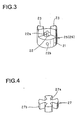
- FIG. 3 is a perspective view of a drive section or a driven section which is a component of a coupling.
- FIG. 4 is a perspective view of an elastic body which is also a component of the coupling.
- FIG. 5 is a perspective view showing a state in which the coupling is attached to a rotary shaft and a screw shaft.
- FIG. 6 is a block diagram of art which is related to the present invention.
-
- Description of the embodiments shown in the drawings will subsequently be given.
- FIG. 1 is a sectional view showing an electromagnetic shock absorber according to a first embodiment.
- A shock absorber body 1 has an
external cylinder 3 and aninternal cylinder 6 which is coaxially inserted in theexternal cylinder 3 in such a manner that theinternal cylinder 6 can freely slide in theexternal cylinder 3. However, a sliding position of theinternal cylinder 6 in theexternal cylinder 3 is located at a lower part of theexternal cylinder 3 which is omitted from the drawing. - Further, a
cylindrical case 7 is coaxially connected at an upper part of theexternal cylinder 3, and amotor 10 housed in ahousing 8 is installed at an upper part of thecase 7. - At an upper end of the
internal cylinder 6 which slides with respect to theexternal cylinder 3, aball nut 16 which constitutes aball screw mechanism 15 is installed. Ascrew shaft 17 to be spirally engaged with theball nut 16 extends to the inside of theinternal cylinder 6. A thread groove of thescrew shaft 17 is guided and spirally engaged with a large number of balls which are arranged on a thread groove in theball nut 16. When theball nut 16 moves in an axial direction together with theinternal cylinder 6, thescrew shaft 17 rotates at the position, more specifically, linear motion of theball nut 16 is converted into rotary motion of thescrew shaft 17. - Additionally, the
ball screw mechanism 15 has a function of converting the linear motion into the rotary motion very smoothly and without resistance by spiral engagement of the large number of balls and the thread groove, and thus theball screw mechanism 15 is the most preferable one. However, a mechanism to convert the linear motion into the rotary motion is not always restricted to theball screw mechanism 15. Theball screw mechanism 15 will not be an obstacle to adoption of another mechanism which has a similar effect. - An upper end of the
screw shaft 17 which goes through theball nut 16 is supported by aball bearing 9 which is installed inside a lower end of thecase 7 through aretention member 8 in such a manner that thescrew shaft 17 can freely rotate and does not fall off downward. - Additionally, an
annular cushion member 5 is installed on a lower surface of theretention member 8. When theinternal cylinder 6 goes up, theannular cushion member 5 elastically meets with theinternal cylinder 6 at the uppermost position so that the shock is cushioned and also a further upward movement of theinternal cylinder 6 is stopped. - Although the details will be described later, a
torsion bar 13 is first arranged as a power transmitting section at a case shaft center section in thecase 7. An upper end of thescrew shaft 17 is inserted at a lower end of thetorsion bar 13 and fixed by a key or the like so as to prevent mutual rotations. An upper end of thetorsion bar 13 is coaxially connected with arotary shaft 11 of themotor 10 by acoupling 14. - A bracket not shown in the drawing is installed above the
external cylinder 3 and at an upper end of thehousing 8 in which themotor 10 is housed. A bracket is also installed at a lower end of theinternal cylinder 6. Between the brackets, using the upper bracket, connection with the car body side is made, on the other hand, using the lower bracket, connection with the axle side is made. - Due to such constitution as described above, when external force, such as pushing up force or vibration, inputs into the
internal cylinder 6 which is at a lower part of the shock absorber body 1 while a vehicle is traveling, theinternal cylinder 6 moves in axial direction with respect to theexternal cylinder 3 in response to the input, more particularly, telescopic motion such as ascent and descent is made. - Due to the
ball screw mechanism 15 composed of theball nut 16, which is installed at theinternal cylinder 6, and thescrew shaft 17 which is connected with themotor 10 through the power transmitting section, linear motion of theinternal cylinder 6 is converted into rotary motion of thescrew shaft 17 at this time. In this case, a direction of the rotary motion of thescrew shaft 17 is switched according to a direction of movement of theball nut 16, and the direction of the rotary motion differs depending on the cases that theinternal cylinder 6 shrinks and extends with respect to theexternal cylinder 3. - The rotary motion of the
screw shaft 17 is transmitted to therotary shaft 11 of themotor 10 through thetorsion bar 13 and thecoupling 14 and thus rotation driving force acts on themotor 10. - With respect to the
motor 10, coils of respective magnetic poles are electrically connected to each other or connected via a control circuit. Thus, when rotary torque is transmitted to therotary shaft 11 of themotor 10, induced electromotive force occurs to the coils and electromagnetic force which opposes against an input of rotations of the motor is always generated. This electromagnetic resistance restrains rotary motion of thescrew shaft 17, and after all resistance is applied to telescopic motion of the shock absorber body 1 which is linear motion of theinternal cylinder 6 so as to generate damping force by the electromagnetic shock absorber. - The
motor 10 functions as a source of the outbreak of the electromagnetic resistance and various motors, such as a direct current motor, an alternating current motor, or an induction motor, are applicable. - To take the case of the direct current motor, although it is not shown in the drawing, in the case of a motor with direct current brush, a stator to which a plurality of permanent magnets for generating magnetic fields are attached and a rotor to which coils constituting a plurality of magnetic poles are attached are arranged in the motor. Coils of respective magnetic poles are connected to each other and thus the rotary shaft of the motor is rotated and the rotor rotates. Whichever direction the motor is rotated when the coils generate induced electromotive force by going across magnetic fields generated by permanent magnets, electromagnetic force which acts on the motor as resistance against rotations of the motor is generated. Thus, as described above, damping force which opposes against vibration or the like to be input into the electromagnetic shock absorber is generated.
- Strength of the electromagnetic force to be generated by the coils can freely and instantaneously be adjusted, for example, by switching the strength of resistance of the control circuit to be connected with coils of respective magnetic poles. Thus, it is possible to freely and promptly control the damping force which is generated according to driving status of a vehicle or the like.
- Next, detailed description of the power transmitting section will be given. The power transmitting section is composed of the
torsion bar 13, which is an elastic deformation member, and thecoupling 14 which is connected with thetorsion bar 13. - The
torsion bar 13 is formed in one united body by a slender, stick-typetorsion bar body 13c with a smaller sectional area, a lower connectingsection 13b which is provided at a lower end of thebody 13c and has a sectional area larger than that of thebody 13c, an opening 13a which is concentrically provided at a lower end of the connectingsection 13b, and an upper connectingsection 13d which is provided at an upper end of thebody 13c. - Further, the
coupling 14 has a stepped hole 14a therein and is roughly cylindrical. Therotary shaft 11 of themotor 10 is inserted into the stepped hole 14a from above, on the other hand, the upper connectingsection 13d of thetorsion bar 13 is inserted from bottom. - A key way is provided at the
rotary shaft 11 and the stepped hole 14a, respectively, and a key 12a is inserted into the key way, so that therotary shaft 11 and thecoupling 14 are connected to prevent their idle running. - Further, in order to fix the
rotary shaft 11 and the connectingsection 13d, athread hole 14b and athread hole 14c are provided at an upper part and a lower part of a lateral surface of thecoupling 14, respectively, in such a manner that thesethread holes rotary shaft 11 and thetorsion bar 13 to prevent their mutual idle running. - Further, an upper end of the
screw shaft 17 is connected to a lower end of thetorsion bar 13. Thus, the upper end of thescrew shaft 17 is inserted into the opening 13a of thetorsion bar 13, and a key 12b is inserted into a key way provided on an insertion surface of the opening 13a and thescrew shaft 17, so that thetorsion bar 13 and thescrew shaft 17 are connected to prevent their mutual idle running. - Next, operation will be described.
- In the case that the electromagnetic shock absorber is applied as a suspension of a vehicle, when an impact from a surface of a road, such as pushing up force or vibration, acts on the
internal cylinder 6 while the vehicle is driving, theinternal cylinder 6 makes linear motion in a direction of the telescopic motion along theexternal cylinder 3. The linear motion of theball nut 16 which moves together with theinternal cylinder 6 in one united body is converted into rotary motion of thescrew shaft 17 by theball screw mechanism 15. - Because the
screw shaft 17 is connected with therotary shaft 11 of themotor 10 through thetorsion bar 13 and thecoupling 14, therotary shaft 11 of themotor 10 also rotates. - When the
rotary shaft 11 of themotor 10 rotates, the coils inside themotor 10 go across the magnetic fields of permanent magnets. Thus, induced electromotive force is generated and electromagnetic force is generated so as to oppose against rotations of themotor 10. Because therotary shaft 11 is connected with thescrew shaft 17 through thetorsion bar 13, the electromagnetic force operates to restrain the rotational movement of thescrew shaft 17 and the movement of theball nut 16 in a direction of telescopic motion of the shock absorber is restrained. More specifically, the electromagnetic force operates as damping force to restrain the linear motion of theinternal cylinder 6 along theexternal cylinder 3 and in a direction of telescopic motion, impact energy from the surface of a road is absorbed and eased, a vehicle is made more comfortable to drive, and drivability is improved. - Additionally, when rotary force, namely, rotary torque is applied to the
torsion bar 13 which is about to rotate in response to the rotary movement of thescrew shaft 17 due to vibration or the like which inputs in the electromagnetic shock absorber from outside, thetorsion bar 13 absorbs the rotary force and while being twisted according to the torque, thetorsion bar 13 transmits the torque not only to thecoupling 14, but also to therotary shaft 11 of themotor 10. - Therefore, rotary motion of the
torsion bar 13 is not directly transmitted to therotary shaft 11. Especially, when thescrew shaft 17 starts rotating or when the rotary speed is changed, it leads to such a phenomenon that a change of the rotary speed of therotary shaft 11 of themotor 10 lags behind a change of the rotary speed of thescrew shaft 17. - Therefore, when the linear motion of the
internal cylinder 6 along theexternal cylinder 3 is commenced or when a speed of the linear motion is changed after great force is applied from an axial direction to theinternal cylinder 6 of the electromagnetic shock absorber, generation of moment of inertia of the rotor of themotor 10 is delayed. - This delays the generation of damping force resulting from moment of inertia of the rotor of the
motor 10, thereby slowing down the generation of the damping force which is hard to control and is generated due to moment of inertia of the rotor when telescopic motion of the electromagnetic shock absorber is commenced or at the initial stage of a speed change. Thus, especially if it is used as an electromagnetic shock absorber of a vehicle, it will make great contributions to realization of a comfortable vehicle to drive. - Additionally, because the
torsion bar 13 transmits rotary motion of thescrew shaft 17 to therotary shaft 11 of themotor 10, it will be sufficient if thetorsion bar 13 is made with materials capable of securing prescribed strength against the torque which may arise due to thescrew shaft 17 or themotor 10. However, an aim of the present invention is that when thescrew shaft 17 commences rotary motion or when the rotary speed changes, transmission of rotations of thescrew shaft 17 to therotary shaft 11 of themotor 10 is delayed. Thus, it is preferable that by changing a sectional area or materials of the cross section of thetorsion bar 13 in the design, torsional rigidity of thetorsion bar 13 is adjusted and a difference of the rotary speed is rendered optimal for a vehicle to which the electromagnetic shock absorber is applied. - Further, for example, if shear strength of the
torsion bar 13 is set so that thebody 13c of thetorsion bar 13 is cut when a rotary torque, which angular acceleration reaches an allowable rotational speed of themotor 10 after a specific time period, for example, one second has passed from the beginning, is applied to thetorsion bar 13, thetorsion bar 13 will be cut when sudden force in an axial direction is applied from the surface of a road to theinternal cylinder 6. Thus, it is possible to avoid that a rotary speed of therotary shaft 11 exceeds the allowable rotary speed of themotor 10 which may arise resulting from sudden telescopic motion of the electromagnetic shock absorber. - Thus, it is possible to prevent a rotary speed of the
rotary shaft 11 of themotor 10 from exceeding the allowable rotary speed of themotor 10, thereby preventing themotor 10 from being subjected to damage which may arise resulting from heat generated by the coils of themotor 10. - Further, it is possible to prevent the
motor 10 which is more expensive than other parts from being damaged even though thetorsion bar 13 is cut. Therefore, a function of the electromagnetic shock absorber can be recovered merely by exchanging thetorsion bar 13 even when it is required to repair the electromagnetic shock absorber, whereby it has the effect of reducing the repair cost. - In the case that the electromagnetic shock absorber is applied to a vehicle, as described above, even though the
torsion bar 13 is cut, it will be possible to avoid a state of being incapable of traveling although damping characteristics are lost if a suspension spring is installed together with the electromagnetic shock absorber because the vehicle is supported by the suspension spring. - Further, in this embodiment, the
torsion bar 13 is used for the power transmitting section in consideration of facilitation in installation and fabrication. However, the present invention is directed to delay the generation of damping force due to moment of inertia of the rotor of themotor 10 by producing a difference of the rotary speed described above. Thus, for example, an electromagnetic clutch may be used for the power transmitting section. - Further, the
torsion bar 13 is formed in one united body as described above, but it is not always restricted to this type. As long as it has a part which is twisted by rotary torque to be input, another configuration is acceptable. - Further, from viewpoint of the present invention, it is desirable that the
coupling 14 has small moment of inertia, if possible. - Next, description of a second embodiment shown in FIG. 2 through FIG. 5 will be given.
- In this embodiment, the constitution is such that a
coupling 24 in which an elastic body is arranged is provided as the power transmitting section described above, whereby transmission of rotary torque is delayed, and when rotary torque which a rotary speed of themotor 10 exceeds an allowable limit speed is applied, a vulnerable section is cut and transmission of the rotary torque is stopped. - In this embodiment, the
screw shaft 17 is directly connected with therotary shaft 11 of themotor 10 by thecoupling 24. - As shown in FIG. 3 through FIG. 5, the
coupling 24 is composed of a pair of adrive section 25 and a drivensection 26 which are constituted identically with each other and anelastic body 27 which is interposed between thedrive section 25 and the drivensection 26. - Because the
drive section 25 and the drivensection 26 have the identical constitution, only one will be described. - As also shown in FIG. 3, a
hole 22 is bored through the center of acylindrical body 21 and akey way 22a is formed on an inner circumferential surface of thehole 22. Therotary shaft 11 of themotor 10 or thescrew shaft 17 is inserted in thehole 22, and a key way not shown in the drawing is provided at therotary shaft 11 and thescrew shaft 17 as a mating key way of thekey way 22a, respectively. A key 19a or 19b is inserted between thekey way 22a and the key way of therotary shaft 11 or the key way of thescrew shaft 17. Thus, thecylindrical body 21 is connected with therotary shaft 11 or thescrew shaft 17 to prevent their idle running. Additionally, athread hole 22b which is bored through thehole 22 is formed on a side surface of thecylindrical body 21, and aspiral engaging stopper 22c is spirally engaged with thethread hole 22b, whereby therotary shaft 11 or thescrew shaft 17 is fixed to prevent therotary shaft 11 or thescrew shaft 17 from coming out in an axial direction. - Also, a pair of
projections 23 are provided at the positions, which are symmetric with thehole 22 as the center, of end surfaces of thecylindrical body 21 which face each other. The projections are trapezoidal and, as it will be described later, form such a vulnerable section that theprojections 23 are cut at the roots when strong torque acts in a direction of rotations. - As also shown in FIG. 5, the
drive section 25 and the drivensection 26 are combined in such a manner that their end surfaces face each other, and theprojections 23 are engaged in such a manner that anelastic body 27 is interposed between theprojections 23. - Therefore, as shown in FIG. 4, the
elastic body 27 is formed by acylindrical body 27a in the center and aspacer section 27b which extends from thecylindrical body 27a crosswise and in all directions. Thespacer section 27b is formed in a shape of inverted trapezoid in such a manner that thespacer section 27b fits between theprojection 23 and theprojection 23 to be combined, namely, on a transmission surface of rotary torque leaving no space between them. Also, it is set that thickness of theelastic body 27 in an axial direction is approximately same as height of theprojections 23 in axial direction of thedrive section 25 and the drivensection 26. - It is preferable that material of the
elastic body 27 is a member which is easy of elastic deformation, such as rubber, but other materials, for example synthetic resin,, are also acceptable. - FIG. 5 shows a state in which the
screw shaft 17 is connected with thedrive section 25 of thecoupling 24 and therotary shaft 11 of themotor 10 is connected with the drivensection 26. In such a manner, thescrew shaft 17 and therotary shaft 11 are connected by means of thecoupling 24 which elastic deformation in a direction of transmission of the rotary torque is possible. Thus, thrust, vibration or the like from the surface of a road acts on the electromagnetic shock absorber while a vehicle is traveling. When the linear motion of theinternal cylinder 6 along theexternal cylinder 3 is converted into the rotary motion of thescrew shaft 17 by theball screw mechanism 15, rotations of thescrew shaft 17 are transmitted to therotary shaft 11 of themotor 10 through thecoupling 24. - At this time, when rotary torque is applied from the screw shaft to the
elastic body 27 which intervenes between thedrive section 25 and the drivensection 26, while shrinking in response to the torque, theelastic body 27 transmits the torque to therotary shaft 11. In this case, if the rotary speed of thescrew shaft 17 changes, transmission of the rotary speed to therotary shaft 11 will be delayed according to quantity of compression of theelastic body 27. - More specifically, if external force in an axial direction is applied to the
internal cylinder 6 of the electromagnetic shock absorber and the acceleration of the linear motion of theinternal cylinder 6 along theexternal cylinder 3 is changed, the generation of moment of inertia of the rotor of themotor 10 will be delayed. - Thus, similarly to the above, it is possible to restrain generation of the damping force which is hard to control and is generated due to the moment of inertia of the rotor at the initial stage of telescopic motion of the electromagnetic shock absorber. Also, if the electromagnetic shock absorber is used as a shock absorber of a vehicle, it will make contributions to realization of a more comfortable vehicle to drive.
- Further, by setting such that when rotary torque which a rotary speed of the
motor 10 exceeds an allowable rotary speed inputs from thescrew shaft 17, theprojections 23 of thedrive section 25 and the drivensection 26 of thecoupling 24 are broken, it is possible to prevent themotor 10 from being subjected to damage which may arise resulting from calorification at the time of exceeding an allowable rotary speed of themotor 10. - A cross section of the
projection 23 is formed in a shape of trapezoid or sector in consideration of facilitation of processing work. However, the present invention aims that theprojection 23 transmits rotary motion and when rotary torque greater than a fixed level is applied, the projection is broken. Thus, it is not restricted to the above-mentioned shape and other shapes are acceptable. - Further, a pair of
projections 23 are provided at thedrive section 25 and the drivensection 26, respectively, but three or more projections may be provided at thedrive section 25 and the drivensection 26, respectively. - Each of the embodiments described above exemplifies that in the process of constituting the ball screw mechanism, the screw shaft is connected with the rotary shaft of the motor and the ball nut is connected with the internal cylinder, respectively. However, it is not restricted to the example. Of course, it is also possible to have such constitution that the screw shaft is fixed to the internal cylinder and slides with the internal cylinder in one united body without rotating, on the other hand, the ball nut is connected with the rotary shaft of the motor, the ball nut is rotated in response to movement of the screw shaft, and the rotary motion is transmitted to the motor.
- The present invention is not restricted to the embodiments described above. It is obvious that the present invention includes various improvement and modification which can be made by a person skilled in the art within a scope of technical ideas given in the following claims.
- The electromagnetic shock absorber according to the present invention can be applied as a shock absorber for a vehicle or the like.
Claims (10)
- An electromagnetic shock absorber comprising:a shock absorber body which makes telescopic motion in response to an input from outside;a ball screw mechanism which is arranged at the shock absorber body, converts the telescopic motion into rotary motion, and is composed of a ball nut and a screw shaft;a motor which is provided at the shock absorber body and generates electromagnetic resistance to oppose against rotations to be input into a rotary shaft of the motor; anda power transmitting section having an elastic body which transmits rotary motion of the ball screw mechanism to the rotary shaft of the motor and also shifts a transmission phase of the rotary motion when rotation torque of the rotary motion is changed.
- An electromagnetic shock absorber according to claim 1, wherein the screw shaft is coaxially connected with the rotary shaft of the motor through the power transmitting section.
- An electromagnetic shock absorber according to claim 2, wherein the shock absorber body is composed of an external cylinder and an internal cylinder to be slidably inserted into the external cylinder, the motor is attached to the external cylinder, the ball nut of the ball screw mechanism is fixed to the internal cylinder, the screw shaft to be spirally engaged with the ball nut is rotatably supported by the external cylinder, and also the screw shaft is connected with the rotary shaft of the motor through the power transmitting section.
- An electromagnetic shock absorber according to any one of claims 1 through 3, wherein the power transmitting section is constituted such that at least a part of the power transmitting section includes a torsion bar.
- An electromagnetic shock absorber according to claim 4, wherein the rotary shaft of the motor is connected with one end of the torsion bar and the screw shaft of the ball screw mechanism is connected with the other end of the torsion bar, respectively, and it is set such that the torsion bar will break if the rotation torque is greater than a prescribed value.
- An electromagnetic shock absorber according to any one of claims 1 through 3, wherein the power transmitting section is constituted such that the power transmitting section is composed of a drive section and a driven section and the elastic body is provided on a torque transmission surface which intervenes between the drive section and the driven section.
- An electromagnetic shock absorber according to claim 6, wherein the rotary shaft of the motor is connected with the drive section and the screw shaft of the ball screw mechanism is connected with the driven section, respectively.
- An electromagnetic shock absorber according to claim 6 or claim 7, wherein the drive section and the driven section are coaxially arranged at the power transmitting section in such a manner that the drive section and the driven section face each other, the drive section and the driven section have projections which project toward respective opposite surfaces and are engaged to each other in a direction of rotations, and the elastic body which intervenes between engaged surfaces of the projections is provided.
- An electromagnetic shock absorber according to claim 8, wherein the projections are constituted such that the projections will break if the rotation torque is greater than a prescribed value.
- An electromagnetic shock absorber according to claim 5 or claim 9, wherein the prescribed value corresponds to a torque value at a time when a rotational speed of the motor to be rotated due to the rotation torque reaches an allowable rotational speed.
Applications Claiming Priority (5)
| Application Number | Priority Date | Filing Date | Title |
|---|---|---|---|
| JP2002155080 | 2002-05-29 | ||
| JP2002155080A JP4305895B2 (en) | 2002-05-29 | 2002-05-29 | Electromagnetic shock absorber |
| JP2002165784A JP2004011753A (en) | 2002-06-06 | 2002-06-06 | Electromagnetic shock absorber |
| JP2002165784 | 2002-06-06 | ||
| PCT/JP2003/006670 WO2003100291A1 (en) | 2002-05-29 | 2003-05-28 | Electromagnetic shock absorber |
Publications (3)
| Publication Number | Publication Date |
|---|---|
| EP1515064A1 true EP1515064A1 (en) | 2005-03-16 |
| EP1515064A4 EP1515064A4 (en) | 2005-08-31 |
| EP1515064B1 EP1515064B1 (en) | 2006-06-14 |
Family
ID=29586000
Family Applications (1)
| Application Number | Title | Priority Date | Filing Date |
|---|---|---|---|
| EP03730663A Expired - Fee Related EP1515064B1 (en) | 2002-05-29 | 2003-05-28 | Electromagnetic shock absorber |
Country Status (7)
| Country | Link |
|---|---|
| US (1) | US7357229B2 (en) |
| EP (1) | EP1515064B1 (en) |
| KR (1) | KR100622465B1 (en) |
| CN (1) | CN100359203C (en) |
| DE (1) | DE60306159T2 (en) |
| ES (1) | ES2265573T3 (en) |
| WO (1) | WO2003100291A1 (en) |
Cited By (2)
| Publication number | Priority date | Publication date | Assignee | Title |
|---|---|---|---|---|
| WO2012112296A1 (en) * | 2011-02-17 | 2012-08-23 | Johnson Controls Technology Company | Magnetic attenuator |
| DE102016218921A1 (en) | 2016-09-29 | 2018-03-29 | Schaeffler Technologies AG & Co. KG | independent suspension |
Families Citing this family (25)
| Publication number | Priority date | Publication date | Assignee | Title |
|---|---|---|---|---|
| ES2347783T3 (en) * | 2004-04-20 | 2010-11-04 | Kayaba Industry Co., Ltd. | ELECTROMAGNETIC SHOCK ABSORBER FOR A VEHICLE. |
| JP4584651B2 (en) * | 2004-08-25 | 2010-11-24 | カヤバ工業株式会社 | Shock absorber |
| JP4455974B2 (en) * | 2004-10-22 | 2010-04-21 | トヨタ自動車株式会社 | Vehicle suspension system |
| EP1942020B1 (en) * | 2005-10-26 | 2011-06-08 | Toyota Jidosha Kabushiki Kaisha | Suspension system for vehicle |
| JP5086830B2 (en) * | 2008-02-08 | 2012-11-28 | 株式会社キーエンス | Image inspection apparatus, image inspection method, and computer program |
| US8070169B2 (en) * | 2008-07-10 | 2011-12-06 | Hyundai Motor Company | Actuator for active roll control system |
| US8044629B2 (en) * | 2008-08-29 | 2011-10-25 | Northern Illinois University | Self-tuning vibration absorber |
| DE102010013935A1 (en) | 2010-04-06 | 2011-10-06 | Schaeffler Technologies Gmbh & Co. Kg | shock absorber |
| US9657806B2 (en) * | 2014-12-09 | 2017-05-23 | Honda Motor Co., Ltd. | Electromagnetic damper |
| US9966829B2 (en) | 2015-11-24 | 2018-05-08 | Lin Engineering, Inc. | Reduced-vibration stepper motor |
| US10088006B2 (en) * | 2016-05-19 | 2018-10-02 | The Boeing Company | Rotational inerter and method for damping an actuator |
| US10107347B2 (en) * | 2016-05-19 | 2018-10-23 | The Boeing Company | Dual rack and pinion rotational inerter system and method for damping movement of a flight control surface of an aircraft |
| US10145434B2 (en) * | 2016-05-19 | 2018-12-04 | The Boeing Company | Translational inerter assembly and method for damping movement of a flight control surface |
| DE102016216498A1 (en) | 2016-09-01 | 2018-03-01 | Schaeffler Technologies AG & Co. KG | shock absorber |
| DE102016221206B4 (en) | 2016-10-27 | 2018-05-09 | Schaeffler Technologies AG & Co. KG | Electromechanical suspension actuator |
| CN106760846B (en) * | 2016-12-16 | 2022-12-20 | 同济大学 | Serial acceleration inertia energy dissipater |
| US20180251123A1 (en) * | 2016-12-30 | 2018-09-06 | Axel Michael Sigmar | Active Series Hybrid Integrated Electric Vehicle |
| US10094683B1 (en) * | 2017-05-15 | 2018-10-09 | Motion Instruments, Inc. | Magnetically actuated pressure sensitive suspension position sensor |
| CN107401112A (en) * | 2017-09-07 | 2017-11-28 | 湖南科技大学 | A kind of electromagnetic rotating inertia mass damper |
| CN108061121A (en) * | 2018-01-08 | 2018-05-22 | 华中科技大学 | A kind of tuning inertia mass electromagnetic damper |
| CN111114842B (en) * | 2018-10-30 | 2022-07-22 | 哈尔滨工业大学 | Electromagnetic and elastic damping composite energy-absorbing folding asteroid surface landing device |
| CN113525011B (en) * | 2020-04-15 | 2024-04-16 | 广州汽车集团股份有限公司 | Automobile suspension becomes rigidity vibration damper and car |
| DE102020119406A1 (en) | 2020-07-22 | 2022-01-27 | Klaus W. Scheibe | Hybrid monotube shock absorber |
| CN112901695B (en) * | 2021-01-20 | 2023-08-22 | 扬州大学 | Electromagnetic shock absorber with asymmetric damping characteristics and asymmetric characteristic design method |
| CN113062486B (en) * | 2021-03-26 | 2022-08-02 | 华中科技大学 | Tuned viscous inertial mass damper with electromagnetic damping |
Citations (1)
| Publication number | Priority date | Publication date | Assignee | Title |
|---|---|---|---|---|
| DE3522221A1 (en) * | 1984-06-27 | 1986-02-27 | Volkswagen AG, 3180 Wolfsburg | Vibration damper arrangement for a vehicle with an electro-dynamic torsional vibration damper |
Family Cites Families (18)
| Publication number | Priority date | Publication date | Assignee | Title |
|---|---|---|---|---|
| US2706897A (en) * | 1953-04-17 | 1955-04-26 | Holoye Jules Alfred | Elastic coupling device for connecting two shafts in line with each other |
| JPS57205422A (en) | 1981-06-09 | 1982-12-16 | Diafoil Co Ltd | Production of polyester |
| JPS6114750Y2 (en) * | 1981-06-26 | 1986-05-08 | ||
| JPS622027A (en) * | 1985-06-25 | 1987-01-08 | Yunikamu:Kk | Decelerating mechanism |
| JP2552111B2 (en) | 1986-03-14 | 1996-11-06 | セイコーエプソン株式会社 | Dot printer wire guide mechanism |
| US5060959A (en) * | 1988-10-05 | 1991-10-29 | Ford Motor Company | Electrically powered active suspension for a vehicle |
| JPH0391551A (en) | 1989-09-01 | 1991-04-17 | Matsushita Electric Ind Co Ltd | Abrasive coating material |
| JP2552111Y2 (en) * | 1989-12-28 | 1997-10-27 | 三和テッキ株式会社 | Generator braking type vibration suppression device |
| US5214975A (en) * | 1990-11-20 | 1993-06-01 | New Venture Gear, Inc. | Transmission vibration damping |
| US5070284A (en) * | 1991-01-14 | 1991-12-03 | Ford Motor Company | Fail-safe variable damping suspension for a motor vehicle |
| JP3016263B2 (en) | 1991-02-27 | 2000-03-06 | 株式会社ユニシアジェックス | Suspension device |
| JPH08197931A (en) * | 1995-01-23 | 1996-08-06 | Honda Motor Co Ltd | Active suspension device |
| JP4197081B2 (en) | 1999-12-20 | 2008-12-17 | 株式会社デンソー | Power transmission device |
| CN2486370Y (en) * | 2001-06-24 | 2002-04-17 | 李辉 | Electromagnetic damper |
| CN100387863C (en) * | 2002-06-06 | 2008-05-14 | 萱场工业株式会社 | Electromagnetic buffer |
| US20050230201A1 (en) * | 2004-04-16 | 2005-10-20 | Takuhiro Kondou | Electromagnetic shock absorber for vehicle |
| JP3722127B2 (en) * | 2003-02-05 | 2005-11-30 | 日産自動車株式会社 | Electromagnetic suspension device for vehicle |
| JP4584651B2 (en) * | 2004-08-25 | 2010-11-24 | カヤバ工業株式会社 | Shock absorber |
-
2003
- 2003-05-28 CN CNB038154846A patent/CN100359203C/en not_active Expired - Fee Related
- 2003-05-28 WO PCT/JP2003/006670 patent/WO2003100291A1/en active IP Right Grant
- 2003-05-28 US US10/515,812 patent/US7357229B2/en not_active Expired - Fee Related
- 2003-05-28 KR KR1020047019124A patent/KR100622465B1/en not_active IP Right Cessation
- 2003-05-28 ES ES03730663T patent/ES2265573T3/en not_active Expired - Lifetime
- 2003-05-28 DE DE60306159T patent/DE60306159T2/en not_active Expired - Lifetime
- 2003-05-28 EP EP03730663A patent/EP1515064B1/en not_active Expired - Fee Related
Patent Citations (1)
| Publication number | Priority date | Publication date | Assignee | Title |
|---|---|---|---|---|
| DE3522221A1 (en) * | 1984-06-27 | 1986-02-27 | Volkswagen AG, 3180 Wolfsburg | Vibration damper arrangement for a vehicle with an electro-dynamic torsional vibration damper |
Non-Patent Citations (1)
| Title |
|---|
| See also references of WO03100291A1 * |
Cited By (2)
| Publication number | Priority date | Publication date | Assignee | Title |
|---|---|---|---|---|
| WO2012112296A1 (en) * | 2011-02-17 | 2012-08-23 | Johnson Controls Technology Company | Magnetic attenuator |
| DE102016218921A1 (en) | 2016-09-29 | 2018-03-29 | Schaeffler Technologies AG & Co. KG | independent suspension |
Also Published As
| Publication number | Publication date |
|---|---|
| DE60306159T2 (en) | 2006-10-05 |
| DE60306159D1 (en) | 2006-07-27 |
| US7357229B2 (en) | 2008-04-15 |
| EP1515064A4 (en) | 2005-08-31 |
| ES2265573T3 (en) | 2007-02-16 |
| KR20040111705A (en) | 2004-12-31 |
| WO2003100291A1 (en) | 2003-12-04 |
| CN100359203C (en) | 2008-01-02 |
| EP1515064B1 (en) | 2006-06-14 |
| CN1666031A (en) | 2005-09-07 |
| US20050212189A1 (en) | 2005-09-29 |
| KR100622465B1 (en) | 2006-09-13 |
Similar Documents
| Publication | Publication Date | Title |
|---|---|---|
| EP1515064B1 (en) | Electromagnetic shock absorber | |
| EP1510721B1 (en) | Electromagnetic shock absorber | |
| EP1630450B1 (en) | Damper | |
| JP4500786B2 (en) | Shock absorber | |
| JP4750617B2 (en) | Shock absorber | |
| EP1510722B1 (en) | Electromagnetic damper | |
| US20110056787A1 (en) | Active Electric Torsional Vibration Damper and Method to Realize the Same | |
| JP4305895B2 (en) | Electromagnetic shock absorber | |
| JP4142946B2 (en) | Vehicle electromagnetic shock absorber | |
| JP4985026B2 (en) | Shock absorber | |
| JP4383986B2 (en) | Shock absorber | |
| JP2004011753A (en) | Electromagnetic shock absorber | |
| KR20020041261A (en) | Smart hybrid damper | |
| JP2004011824A (en) | Electromagnetic shock absorber | |
| JP2005264991A (en) | Electromagnetic damper | |
| JP2004011754A (en) | Electromagnetic shock absorber | |
| CN117656734A (en) | Suspension assembly and vehicle with same | |
| JP5233426B2 (en) | Ball spline | |
| JP2004011752A (en) | Electromagnetic shock absorber | |
| JP2006064100A (en) | Damper |
Legal Events
| Date | Code | Title | Description |
|---|---|---|---|
| PUAI | Public reference made under article 153(3) epc to a published international application that has entered the european phase |
Free format text: ORIGINAL CODE: 0009012 |
|
| 17P | Request for examination filed |
Effective date: 20041216 |
|
| AK | Designated contracting states |
Kind code of ref document: A1 Designated state(s): AT BE BG CH CY CZ DE DK EE ES FI FR GB GR HU IE IT LI LU MC NL PT RO SE SI SK TR |
|
| A4 | Supplementary search report drawn up and despatched |
Effective date: 20050714 |
|
| RBV | Designated contracting states (corrected) |
Designated state(s): DE ES FR GB IT |
|
| GRAP | Despatch of communication of intention to grant a patent |
Free format text: ORIGINAL CODE: EPIDOSNIGR1 |
|
| GRAS | Grant fee paid |
Free format text: ORIGINAL CODE: EPIDOSNIGR3 |
|
| GRAA | (expected) grant |
Free format text: ORIGINAL CODE: 0009210 |
|
| AK | Designated contracting states |
Kind code of ref document: B1 Designated state(s): DE ES FR GB IT |
|
| PG25 | Lapsed in a contracting state [announced via postgrant information from national office to epo] |
Ref country code: IT Free format text: LAPSE BECAUSE OF FAILURE TO SUBMIT A TRANSLATION OF THE DESCRIPTION OR TO PAY THE FEE WITHIN THE PRESCRIBED TIME-LIMIT;WARNING: LAPSES OF ITALIAN PATENTS WITH EFFECTIVE DATE BEFORE 2007 MAY HAVE OCCURRED AT ANY TIME BEFORE 2007. THE CORRECT EFFECTIVE DATE MAY BE DIFFERENT FROM THE ONE RECORDED. Effective date: 20060614 |
|
| REG | Reference to a national code |
Ref country code: GB Ref legal event code: FG4D |
|
| REF | Corresponds to: |
Ref document number: 60306159 Country of ref document: DE Date of ref document: 20060727 Kind code of ref document: P |
|
| ET | Fr: translation filed | ||
| REG | Reference to a national code |
Ref country code: ES Ref legal event code: FG2A Ref document number: 2265573 Country of ref document: ES Kind code of ref document: T3 |
|
| PLBE | No opposition filed within time limit |
Free format text: ORIGINAL CODE: 0009261 |
|
| STAA | Information on the status of an ep patent application or granted ep patent |
Free format text: STATUS: NO OPPOSITION FILED WITHIN TIME LIMIT |
|
| 26N | No opposition filed |
Effective date: 20070315 |
|
| PGFP | Annual fee paid to national office [announced via postgrant information from national office to epo] |
Ref country code: ES Payment date: 20110520 Year of fee payment: 9 Ref country code: FR Payment date: 20110523 Year of fee payment: 9 |
|
| PGFP | Annual fee paid to national office [announced via postgrant information from national office to epo] |
Ref country code: GB Payment date: 20110525 Year of fee payment: 9 |
|
| PGFP | Annual fee paid to national office [announced via postgrant information from national office to epo] |
Ref country code: DE Payment date: 20110525 Year of fee payment: 9 Ref country code: IT Payment date: 20110523 Year of fee payment: 9 |
|
| GBPC | Gb: european patent ceased through non-payment of renewal fee |
Effective date: 20120528 |
|
| PG25 | Lapsed in a contracting state [announced via postgrant information from national office to epo] |
Ref country code: IT Free format text: LAPSE BECAUSE OF NON-PAYMENT OF DUE FEES Effective date: 20120528 |
|
| REG | Reference to a national code |
Ref country code: FR Ref legal event code: ST Effective date: 20130131 |
|
| REG | Reference to a national code |
Ref country code: DE Ref legal event code: R119 Ref document number: 60306159 Country of ref document: DE Effective date: 20121201 |
|
| PG25 | Lapsed in a contracting state [announced via postgrant information from national office to epo] |
Ref country code: GB Free format text: LAPSE BECAUSE OF NON-PAYMENT OF DUE FEES Effective date: 20120528 Ref country code: FR Free format text: LAPSE BECAUSE OF NON-PAYMENT OF DUE FEES Effective date: 20120531 |
|
| PG25 | Lapsed in a contracting state [announced via postgrant information from national office to epo] |
Ref country code: DE Free format text: LAPSE BECAUSE OF NON-PAYMENT OF DUE FEES Effective date: 20121201 |
|
| REG | Reference to a national code |
Ref country code: ES Ref legal event code: FD2A Effective date: 20130820 |
|
| PG25 | Lapsed in a contracting state [announced via postgrant information from national office to epo] |
Ref country code: ES Free format text: LAPSE BECAUSE OF NON-PAYMENT OF DUE FEES Effective date: 20120529 |