EP1514781A2 - Support pour fixer des accesoires sur des deux-roues - Google Patents
Support pour fixer des accesoires sur des deux-roues Download PDFInfo
- Publication number
- EP1514781A2 EP1514781A2 EP04019975A EP04019975A EP1514781A2 EP 1514781 A2 EP1514781 A2 EP 1514781A2 EP 04019975 A EP04019975 A EP 04019975A EP 04019975 A EP04019975 A EP 04019975A EP 1514781 A2 EP1514781 A2 EP 1514781A2
- Authority
- EP
- European Patent Office
- Prior art keywords
- clamp
- spring
- klobenaufnahme
- block
- axial
- Prior art date
- Legal status (The legal status is an assumption and is not a legal conclusion. Google has not performed a legal analysis and makes no representation as to the accuracy of the status listed.)
- Granted
Links
Images


Classifications
-
- B—PERFORMING OPERATIONS; TRANSPORTING
- B62—LAND VEHICLES FOR TRAVELLING OTHERWISE THAN ON RAILS
- B62J—CYCLE SADDLES OR SEATS; AUXILIARY DEVICES OR ACCESSORIES SPECIALLY ADAPTED TO CYCLES AND NOT OTHERWISE PROVIDED FOR, e.g. ARTICLE CARRIERS OR CYCLE PROTECTORS
- B62J11/00—Supporting arrangements specially adapted for fastening specific devices to cycles, e.g. supports for attaching maps
-
- B—PERFORMING OPERATIONS; TRANSPORTING
- B62—LAND VEHICLES FOR TRAVELLING OTHERWISE THAN ON RAILS
- B62H—CYCLE STANDS; SUPPORTS OR HOLDERS FOR PARKING OR STORING CYCLES; APPLIANCES PREVENTING OR INDICATING UNAUTHORIZED USE OR THEFT OF CYCLES; LOCKS INTEGRAL WITH CYCLES; DEVICES FOR LEARNING TO RIDE CYCLES
- B62H5/00—Appliances preventing or indicating unauthorised use or theft of cycles; Locks integral with cycles
Definitions
- the invention relates to a holder for fastening an accessory, especially a castle, on a two-wheeler.
- the holder has a cock and a claw recording, each along a Extend longitudinal axis.
- This bracket is thus characterized by a clamp, the on a head is partially widened radially in order to one or more Retaining springs within a receiving space of the Klobenfactafter to be able to lock.
- the block can thus head ahead in axial Direction, i. along its longitudinal axis, in the Klobenamam are introduced, wherein the at least one retaining spring radially for a short time pushed back to the outside and after passing the Klobenkopfs snaps back radially inward.
- the retaining spring is now on axial height of the Klobenschaft, and it is from a Häifungsabexcellent the Klobenkopfs example, after the manner of a blocking nose engaged behind.
- a special feature of this mount is the way in which Claw released from this snap connection with the clamp recording again can be.
- Claw released from this snap connection with the clamp recording again can be.
- the Klobenschaft is not circular, but has trigger projections, on which the Klobenschaft a larger Radius than at respectively adjacent thereto engagement portions, at which the at least one retaining spring after the locking of the block attacks in the claw recording.
- a particular advantage of this holder is also that the Tripping projections and engaging portions of the Klobenschafts and the Schugreifungsabête and release portions of the Klobenkopfs in a regular division, i. e. the cock is re a rotational angle is formed of a certain pitch angle.
- the engaging portions of the Klobenschafts are formed by flat side surfaces. Such a Klobenschaft not only can be made very easy, but the Danger of functional impairment of the holder due to contamination the cock is significantly reduced. Alternatively, you can However, the engaging portions of the Klobenschafts also by concave Vaulting, formed by slots or other recesses be.
- the release projections can easily be replaced by longitudinal edges of the Klobenschafts be formed, especially when the Klobenschaft one has triangular, quadrangular or polygonal cross-section.
- the Schugreifungsabête and / or the release portions of the Klobenkopfs are at their front, i. at the of the Klobenschaft opposite side, preferably designed as a deflection bevel to at the insertion of the clamp in the Klobening the at least one To be able to push back retaining spring.
- the front of the cockhead may be tapered convex, pyramidal or conical.
- the release sections be designed as sliding surfaces or sliding edges, the radially exactly to come close to the respective trigger lead or the respect Tripping projections of the Klobenschafts are set back radially to at the axial removal of the block from the Klobeneffort a slide to allow the at least one retaining spring.
- a radial survey is provided at the axial transition between a triggering projection the Klobenschafts and the corresponding release portion of the Klobenkopfs. In this case, so must for the axial removal of the block from the block holder itself in the second angular position of the block a certain RastBank the relevant holding spring to be overcome.
- the clamp receiver has two retaining springs which diametrically opposite each other with respect to the receiving space are arranged.
- the block locked in the Klobenfact particularly reliable, and the explained self - adjustment of the Clawing in the first angular position is advantageously supported.
- the retaining spring or retaining springs respectively have an elongated spring strip, which is in a relaxed state with respect to the longitudinal axis of the clamp seat in tangential Direction extends along the edge of the receiving space.
- a Elongated spring strip can along its longitudinal extent to the Rear engaging portion of the ram head and / or the engaging portion abut the Klobenschafts and thus for a particularly stable Ensure the seat of the cocking in the clamp seat.
- the claw recording may have a tangential slot from which the spring strip in protrudes into the receiving space or in the back of the spring strip can.
- an axial slot extension i.e. an extension substantially parallel to the longitudinal axis of the Klobenfact.
- the cocks and the claw receiver work If the cock in the first angular position is introduced into the clamp seat in a first axial position, the spring strip extends between the axial slot extensions and is thus of the Klobenfact against a radial scrubdrnature blocked.
- the block is biased axially in the direction of the first axial position.
- the block must be against this bias in the second axial position be converted to a rotation in the second angular position to carry out.
- This axial biasing can in an advantageous Way done by means of at least one retaining spring.
- a separate spring may be provided.
- the Claw has at least one driver section, by the at an axial displacement of the block from the first axial position in the second axial position and the spring strip, as explained, offset axially becomes.
- This spring element may be, for example, a U-shaped Spring clip or a spring clip made of metal or plastic act. This embodiment reduces the assembly effort.
- the at least one Holding spring for example, a radially biased ball or a radial Have resiliently trained spring ring.
- the holder has a rotation locking device, which prevents the block against accidental Twisting from the first angular position to the second angular position guaranteed.
- This anti-rotation device thus causes - alternatively or in addition to the described embodiment of the Klobenfact with axial slot extensions - a stabilization of the block in the first angular position.
- the clamp on the one hand and the Klobenam on the other hand, at least one anti-rotation recess and at least an engaging means - or vice versa - have, wherein in the first Angular position of the inserted into the Klobenam Klobens Engagement means engages resiliently in the anti-rotation recess. Only from a predetermined torque deviates the engagement means the anti-rotation recess and thus gives the block for a Rotary movement in the second angular position free.
- a means of intervention can For example, a preloaded ball or a radially spring-back trained Be provided spring ring.
- the invention also relates to the use of a holder of described type for attaching an accessory to a bicycle.
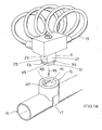
- Fig. 1a shows a clamp 11 made of metal and an associated Klobening 13 made of plastic according to a first embodiment.
- the Claw receptacle 13 is by means of a strap 17, a clamp or The like attached to a portion 19 of a bicycle frame.
- the block 11 has along a longitudinal axis 21 a Klobenschaft 23 and a thereto formed Klobenkopf 25.
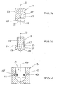
- the Klobenschaft 23 has in a regular Division of 90 ° four engagement sections 27 in the form of planar Side faces.
- the Klobenschaft 23 is thus as a square with square Cross section formed.
- the longitudinal edges of the Klobenschaft each form a trigger projection 29.
- the Klobenschaft 23 facing the rear of the pawl head 25 has the shape of a flat circular area whose diameter is exactly the same Diagonal of the square cross-section of the Klobenschafts 23 corresponds.
- the Klobenkopf 25 can thus be in four spherical segment, subdivide formed as blocking lugs Schugreifungsabête 31.
- the back of each rear engagement portion 31 is adjacent to a side surface or an engagement portion 27 of the Klobenschafts 23 and stands as a stop surface 33 via this engagement portion 27 via.
- the (imaginary) dividing line between these four Stromgreifungsabitesen 31 runs at the front of the block head 25 thus from the end of the respective longitudinal edge 29 of the Klobenschafts 23 to the center the Klobenkopfs 25 at the front.
- This dividing line forms one Release portion 35 of the block head 25, as explained below becomes.
- Fig. 1d possesses the Klobenam 13 substantially the shape of a hollow cylinder open at one end face.
- the Klobenam 13 thus surrounds a receiving space 41st for receiving the block 11.
- the two receiving slots 45 are diametrically opposite each other. From each receiving slot 45 protrudes one Retaining spring in the form of a spring strip 47 out.
- the spring strips 47 are biased radially inwardly with respect to the central longitudinal axis 43 and run parallel to each other.
- the two spring strips 47 are formed for example by wire sections.
- Figs. 1e and 1f show the state thus achieved.
- the concerned Side surfaces or engaging portions 27 of the Klobenschafts 23 are now completely aligned parallel to the foundedgeschnappten spring strips 47.
- the claw head 25 is now locked to the spring strip 47.
- the Spring strips 47 block the block head 25 to the stop surfaces 33rd against a removal from the Klobentext 13.
- the block 11 takes now a first angular position relative to the Klobenage 13 a.
- Fig. 1g and 1h show the state thus achieved.
- the clamp 11 can now easily against the insertion 49 from the Klobenwork 13 are removed, since in such axial movement of the Block 11, the biased spring strips 47 along the remaining Part of the respective longitudinal edge or of the respective trigger projection 29 slide along the Klobenschafts 23 and from there along the adjoining, increasingly radially recessed release section 35 of the block head 25 slide along.
- the holder shown in Fig. 1a to 1h thus has the advantage of a particularly easy handling by the user.
- the one with the castle 15 connected clamp 11 is simply inserted axially into the clamp receiver 13, to automatically lock there.
- To the lock 15 again from the Klobenfact 13 to be able to solve the user only perform a rotation of the block 11, wherein upon reaching the required second angular position of the block 11 for axial removal is released and the spring strips 47, the axial removal movement even support it.
- the block 11 can at least partly made of plastic.
- the Klobentext 13 can alternatively be at least partially made of metal.
- the Klobening 13 may instead of the described hollow cylinder shape also have another hollow or cage shape, in particular the Shape of a one-sided open hollow sphere.
- the clamp receiver has 13 two engagement balls 55, in a respective ball channel 57 are housed.
- the ball channels 57 open at the inner edge of the open end face of the Klobenfact 13.
- the two engagement balls 55th are within the ball channels 57 radially inwardly and with respect to Longitudinal axis 43 of the Klobenfactage 13 biased in an inclined direction.
- the two engagement balls 55 are with respect to the arrangement of two spring strips 47 offset by 90 °, and they are diametrically opposed across from.
- the two engagement balls 55 and two of the four anti-rotation cutouts 53 act together as a rotation locking device.
- the introduced into the Klobenfact 13 clamp 11 is against an unintentional twisting from the first angular position in the secured second angular position.
- Figs. 2e and 2f illustrate this safety principle for the first angular position of the block 11, wherein the sectional plane of FIG. 2e with respect the cutting plane shown in Fig. 1e is rotated by 90 °.
- the spring strips 47 to the Engagement portions 27 of the Klobenschafts 23, as in connection already explained with Fig. 1e.
- the two intervention balls grip 55 each in an associated anti-rotation recess 53rd of the cylinder neck 51 a.
- the block 11 is thereby additionally against secured an unintentional rotation, which the cock 11 in undesirable Can bring way in the second angular position.
- Fig. 2g and 2h show the clamp used in the Klobenfact 13 11 in the second angular position.
- the two engagement balls 55 are now out of engagement with the anti-rotation recesses 53 and are in the ball channels 57 pushed back.
- the clamp 11 can without obstruction removed by the engagement balls 55 from the Klobentext 13 become.
- the bell crank head 25 has a circumferential deflection bevel 62nd
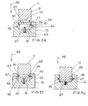
- Each of the two tangential receiving slots 45 on the inner wall of Claw receptacle 13 has at its two ends in each case an axial Slot extension 63, which is parallel to the longitudinal axis 43 of the Klobenfact 13 runs counter to the insertion 49. Between the two Slot extensions 63 of a receiving slot 45 extends Consequently, a blocking portion 65 of the inner wall of the Klobenfact 13.
- the two spring strips 47 are not only radially inward, but additionally biased against the insertion direction 49. Consequently the two spring strips 47 normally pass through an edge region the receiving space 41 between the ends of the two concerned Slot extensions 63.
- Fig. 3e shows the state thus achieved. If the cock 1 1-now is further moved in the insertion direction 49, the deflection bevel 62 presses the plunger head 25, the two spring strips 47 initially still further downward. Once the spring strips 47 the respective blocking section 65 have passed the Klobentext 13, the deflection bevel 62 urges the Klobenkopfs 25 with ongoing axial movement of the block 11 the both spring strips 47 radially outward, i. in the respective receiving slot 45. In addition, the claw head 25 abuts with its front now on the compression spring 67 at.
- the compression spring 67 presses the Claw 11 - preferably supported by an axial bias of Spring strip 47 - a short distance back from the Klobenfact 13 out until the spring strips 47 on the one hand to the relevant stop surfaces 33 of the ram head 25 and on the other hand at the axial Limits of the slot extensions 63 abut.
- Fig. 3f shows the state thus achieved.
- the block 11 is located now in a first axial position.
- the Hintergreifungsabête 31 of the Klobenkopfs 25 engage behind the two spring strips 47th These are from the blocking portions 65 of the inner wall of the Klobenage 13 against blocked a radial retreat. Traverse the spring strips 47 directed against the insertion direction 49 end portions of the Slot extensions 63. The block 11 is thus against removal secured from the Klobenfact 13.
- Fig. 3g shows the state thus achieved, i. the block 11 is located Here in the second axial position and in the second angular position. Of the Claw 11 can now easily against the insertion 49 from the Klobentext 13 are pulled.
- the spring strips 47 and the compression spring 67 at a be formed single spring element.
- This spring element can, for example have a U-shape, each with a spring strip 47 at a leg of the U-shape and the compression spring 67 by a bulge the base of the U-shape are formed.
- the cock 11 is preferably formed as an insert of metal.
- Such a thing Insertion can namely, for example, in the lock body of the Spiral cable lock 15 are integrated or used according to FIG. 1a, even if this lock body is made of plastic.
- the holder is of course also for Attach other accessories, such as lamps, bags or on-board computer, can be used and also for fixing accessories for motorcycles.
Landscapes
- Engineering & Computer Science (AREA)
- Mechanical Engineering (AREA)
- Clamps And Clips (AREA)
Applications Claiming Priority (2)
| Application Number | Priority Date | Filing Date | Title |
|---|---|---|---|
| DE10341783A DE10341783A1 (de) | 2003-09-10 | 2003-09-10 | Halterung zur Befestigung eines Zubehörteils an einem Zweirad |
| DE10341783 | 2003-09-10 |
Publications (3)
| Publication Number | Publication Date |
|---|---|
| EP1514781A2 true EP1514781A2 (fr) | 2005-03-16 |
| EP1514781A3 EP1514781A3 (fr) | 2006-04-26 |
| EP1514781B1 EP1514781B1 (fr) | 2007-10-17 |
Family
ID=34129734
Family Applications (1)
| Application Number | Title | Priority Date | Filing Date |
|---|---|---|---|
| EP04019975A Expired - Lifetime EP1514781B1 (fr) | 2003-09-10 | 2004-08-23 | Support pour fixer des accesoires sur des deux-roues |
Country Status (2)
| Country | Link |
|---|---|
| EP (1) | EP1514781B1 (fr) |
| DE (2) | DE10341783A1 (fr) |
Cited By (1)
| Publication number | Priority date | Publication date | Assignee | Title |
|---|---|---|---|---|
| CN104743010A (zh) * | 2015-04-19 | 2015-07-01 | 成都晨电智能科技有限公司 | 一种自行车附件通用固定装置 |
Family Cites Families (8)
| Publication number | Priority date | Publication date | Assignee | Title |
|---|---|---|---|---|
| DE9013188U1 (de) * | 1990-09-17 | 1992-01-23 | Aug. Winkhaus GmbH & Co KG, 4404 Telgte | Halterungseinrichtung zur Halterung eines Ringschlosses an einem Zweiradrahmen |
| DE4312032C3 (de) * | 1992-04-14 | 1999-09-23 | Rixen & Kaul Gmbh | Kupplung zum Befestigen und Lösen von Ausrüstungsgegenständen |
| DE19627624A1 (de) * | 1995-08-05 | 1997-02-27 | Pietschner Wilfried | Ringschloß zum Sichern von beweglichen Gegenständen, insbesondere Zweirädern oder dergleichen Fahrzeuge, und Halteteil einer Haltevorrichtung für ein Ringschloß |
| DE19532383A1 (de) * | 1995-09-01 | 1997-03-06 | Winkhaus Fa August | Mitführbefestigung eines Zubehörteils an einem mobilen Objekt |
| DE19706560A1 (de) * | 1996-07-09 | 1998-07-30 | Pietschner Wilfried | Ringschloß zum Sichern von beweglichen Gegenständen, insbesondere Zweirädern oder dergleichen Fahrzeuge |
| DE29709959U1 (de) * | 1997-06-07 | 1997-08-07 | Handway Co., Ltd., Changhua | Fahrradschloß-Vorrichtung |
| ES2165250B1 (es) * | 1998-11-12 | 2003-05-16 | Zulaica Urbano Arrizabalaga | Dispositivo de sujecion perfeccionado para un elemento antirrobo de bicicletas, motocicletas y similares. |
| DE29917292U1 (de) * | 1999-10-01 | 2000-01-13 | Aug. Winkhaus GmbH & Co. KG., 48291 Telgte | Befestigungsvorrichtung |
-
2003
- 2003-09-10 DE DE10341783A patent/DE10341783A1/de not_active Withdrawn
-
2004
- 2004-08-23 DE DE502004005248T patent/DE502004005248D1/de not_active Expired - Lifetime
- 2004-08-23 EP EP04019975A patent/EP1514781B1/fr not_active Expired - Lifetime
Cited By (2)
| Publication number | Priority date | Publication date | Assignee | Title |
|---|---|---|---|---|
| CN104743010A (zh) * | 2015-04-19 | 2015-07-01 | 成都晨电智能科技有限公司 | 一种自行车附件通用固定装置 |
| CN104743010B (zh) * | 2015-04-19 | 2019-05-31 | 成都晨电智能科技有限公司 | 一种自行车附件通用固定装置 |
Also Published As
| Publication number | Publication date |
|---|---|
| DE502004005248D1 (de) | 2007-11-29 |
| EP1514781B1 (fr) | 2007-10-17 |
| EP1514781A3 (fr) | 2006-04-26 |
| DE10341783A1 (de) | 2005-04-28 |
Similar Documents
| Publication | Publication Date | Title |
|---|---|---|
| DE69111223T3 (de) | Steckverbinder-Vorrichtung. | |
| DE112007000086B4 (de) | Verbindungsanordnung mit einem Verbindungselement | |
| EP0415355B1 (fr) | Moyens de verrouillage pour une serrure, notamment pour une serrure à câble | |
| DE69415534T2 (de) | Wiederverwendbares siegel für einen stab | |
| DE2813025C2 (de) | Sicherheitsbolzen | |
| EP3256089B1 (fr) | Mâchoire de serrage destinée à être montée sur une glissière d'une table d'opération | |
| EP3109141B1 (fr) | Fixation | |
| DE2629234A1 (de) | Verschlusskappe mit drehkraftbegrenzung | |
| WO2018153931A1 (fr) | Dispositif de fixation et module de fixation | |
| EP2801726B1 (fr) | Boulon d'arrêt | |
| EP2261519A2 (fr) | Vis destinée à la fixation d'un premier composant sur un second composant | |
| EP1819957A1 (fr) | Dispositif de raccordement servant a relier des conduites, et vehicule automobile equipe de ce dispositif de raccordement | |
| EP4098527A1 (fr) | Serrure en châssis | |
| DE202009017354U1 (de) | Arretierungselement | |
| DE2142488A1 (de) | Lösbarer Schraubverbinddr, insbesondere zum Anschluß von Tafeln an Rahmen od. dgl | |
| EP1514781B1 (fr) | Support pour fixer des accesoires sur des deux-roues | |
| DE20212656U1 (de) | Haltebolzenanordnung | |
| WO2015185380A1 (fr) | Serrure pour échafaudage | |
| DE3843852A1 (de) | Steckverbinder | |
| DE102019102768A1 (de) | Drehverschluss | |
| EP1640258B1 (fr) | Dispositif de fixation d'un accessoire | |
| DE10043619A1 (de) | Schnellkupplung zum Verbinden vonn Leitungsenden | |
| EP2317164B1 (fr) | Crochet, notamment pour dispositifs de sécurité | |
| DE19706560A1 (de) | Ringschloß zum Sichern von beweglichen Gegenständen, insbesondere Zweirädern oder dergleichen Fahrzeuge | |
| DE2237024C3 (de) | Schnellkupplung für Flüssigkeits- und Gasleitungen |
Legal Events
| Date | Code | Title | Description |
|---|---|---|---|
| PUAI | Public reference made under article 153(3) epc to a published international application that has entered the european phase |
Free format text: ORIGINAL CODE: 0009012 |
|
| AK | Designated contracting states |
Kind code of ref document: A2 Designated state(s): AT BE BG CH CY CZ DE DK EE ES FI FR GB GR HU IE IT LI LU MC NL PL PT RO SE SI SK TR |
|
| AX | Request for extension of the european patent |
Extension state: AL HR LT LV MK |
|
| PUAL | Search report despatched |
Free format text: ORIGINAL CODE: 0009013 |
|
| AK | Designated contracting states |
Kind code of ref document: A3 Designated state(s): AT BE BG CH CY CZ DE DK EE ES FI FR GB GR HU IE IT LI LU MC NL PL PT RO SE SI SK TR |
|
| AX | Request for extension of the european patent |
Extension state: AL HR LT LV MK |
|
| 17P | Request for examination filed |
Effective date: 20060630 |
|
| 17Q | First examination report despatched |
Effective date: 20060801 |
|
| AKX | Designation fees paid |
Designated state(s): DE FR GB |
|
| GRAP | Despatch of communication of intention to grant a patent |
Free format text: ORIGINAL CODE: EPIDOSNIGR1 |
|
| GRAS | Grant fee paid |
Free format text: ORIGINAL CODE: EPIDOSNIGR3 |
|
| GRAA | (expected) grant |
Free format text: ORIGINAL CODE: 0009210 |
|
| AK | Designated contracting states |
Kind code of ref document: B1 Designated state(s): DE FR GB |
|
| REG | Reference to a national code |
Ref country code: GB Ref legal event code: FG4D Free format text: NOT ENGLISH |
|
| REF | Corresponds to: |
Ref document number: 502004005248 Country of ref document: DE Date of ref document: 20071129 Kind code of ref document: P |
|
| GBT | Gb: translation of ep patent filed (gb section 77(6)(a)/1977) |
Effective date: 20071128 |
|
| ET | Fr: translation filed | ||
| PLBE | No opposition filed within time limit |
Free format text: ORIGINAL CODE: 0009261 |
|
| STAA | Information on the status of an ep patent application or granted ep patent |
Free format text: STATUS: NO OPPOSITION FILED WITHIN TIME LIMIT |
|
| 26N | No opposition filed |
Effective date: 20080718 |
|
| REG | Reference to a national code |
Ref country code: FR Ref legal event code: PLFP Year of fee payment: 13 |
|
| REG | Reference to a national code |
Ref country code: FR Ref legal event code: PLFP Year of fee payment: 14 |
|
| PGFP | Annual fee paid to national office [announced via postgrant information from national office to epo] |
Ref country code: FR Payment date: 20170822 Year of fee payment: 14 Ref country code: GB Payment date: 20170822 Year of fee payment: 14 |
|
| PGFP | Annual fee paid to national office [announced via postgrant information from national office to epo] |
Ref country code: DE Payment date: 20171030 Year of fee payment: 14 |
|
| REG | Reference to a national code |
Ref country code: DE Ref legal event code: R119 Ref document number: 502004005248 Country of ref document: DE |
|
| GBPC | Gb: european patent ceased through non-payment of renewal fee |
Effective date: 20180823 |
|
| PG25 | Lapsed in a contracting state [announced via postgrant information from national office to epo] |
Ref country code: DE Free format text: LAPSE BECAUSE OF NON-PAYMENT OF DUE FEES Effective date: 20190301 |
|
| PG25 | Lapsed in a contracting state [announced via postgrant information from national office to epo] |
Ref country code: FR Free format text: LAPSE BECAUSE OF NON-PAYMENT OF DUE FEES Effective date: 20180831 |
|
| PG25 | Lapsed in a contracting state [announced via postgrant information from national office to epo] |
Ref country code: GB Free format text: LAPSE BECAUSE OF NON-PAYMENT OF DUE FEES Effective date: 20180823 |