EP1514745B1 - Module de sac gonflable - Google Patents
Module de sac gonflable Download PDFInfo
- Publication number
- EP1514745B1 EP1514745B1 EP20030020893 EP03020893A EP1514745B1 EP 1514745 B1 EP1514745 B1 EP 1514745B1 EP 20030020893 EP20030020893 EP 20030020893 EP 03020893 A EP03020893 A EP 03020893A EP 1514745 B1 EP1514745 B1 EP 1514745B1
- Authority
- EP
- European Patent Office
- Prior art keywords
- airbag
- envelope
- fixing
- accordance
- package
- Prior art date
- Legal status (The legal status is an assumption and is not a legal conclusion. Google has not performed a legal analysis and makes no representation as to the accuracy of the status listed.)
- Expired - Lifetime
Links
- 239000000463 material Substances 0.000 claims description 21
- 238000004519 manufacturing process Methods 0.000 claims description 11
- 238000000034 method Methods 0.000 claims description 9
- 230000015572 biosynthetic process Effects 0.000 claims description 3
- 230000003313 weakening effect Effects 0.000 description 13
- 239000000725 suspension Substances 0.000 description 4
- 230000001419 dependent effect Effects 0.000 description 2
- 238000009958 sewing Methods 0.000 description 2
- 230000006835 compression Effects 0.000 description 1
- 238000007906 compression Methods 0.000 description 1
- 230000009977 dual effect Effects 0.000 description 1
- 239000004744 fabric Substances 0.000 description 1
- 230000006870 function Effects 0.000 description 1
- 238000009434 installation Methods 0.000 description 1
- 230000009993 protective function Effects 0.000 description 1
Images


Classifications
-
- B—PERFORMING OPERATIONS; TRANSPORTING
- B60—VEHICLES IN GENERAL
- B60R—VEHICLES, VEHICLE FITTINGS, OR VEHICLE PARTS, NOT OTHERWISE PROVIDED FOR
- B60R21/00—Arrangements or fittings on vehicles for protecting or preventing injuries to occupants or pedestrians in case of accidents or other traffic risks
- B60R21/02—Occupant safety arrangements or fittings, e.g. crash pads
- B60R21/16—Inflatable occupant restraints or confinements designed to inflate upon impact or impending impact, e.g. air bags
- B60R21/20—Arrangements for storing inflatable members in their non-use or deflated condition; Arrangement or mounting of air bag modules or components
- B60R21/217—Inflation fluid source retainers, e.g. reaction canisters; Connection of bags, covers, diffusers or inflation fluid sources therewith or together
- B60R21/2176—Inflation fluid source retainers, e.g. reaction canisters; Connection of bags, covers, diffusers or inflation fluid sources therewith or together the air bag components being completely enclosed in a soft or semi-rigid housing or cover
-
- B—PERFORMING OPERATIONS; TRANSPORTING
- B60—VEHICLES IN GENERAL
- B60R—VEHICLES, VEHICLE FITTINGS, OR VEHICLE PARTS, NOT OTHERWISE PROVIDED FOR
- B60R21/00—Arrangements or fittings on vehicles for protecting or preventing injuries to occupants or pedestrians in case of accidents or other traffic risks
- B60R21/02—Occupant safety arrangements or fittings, e.g. crash pads
- B60R21/16—Inflatable occupant restraints or confinements designed to inflate upon impact or impending impact, e.g. air bags
- B60R21/20—Arrangements for storing inflatable members in their non-use or deflated condition; Arrangement or mounting of air bag modules or components
- B60R21/201—Packaging straps or envelopes for inflatable members
-
- B—PERFORMING OPERATIONS; TRANSPORTING
- B60—VEHICLES IN GENERAL
- B60R—VEHICLES, VEHICLE FITTINGS, OR VEHICLE PARTS, NOT OTHERWISE PROVIDED FOR
- B60R21/00—Arrangements or fittings on vehicles for protecting or preventing injuries to occupants or pedestrians in case of accidents or other traffic risks
- B60R21/02—Occupant safety arrangements or fittings, e.g. crash pads
- B60R21/16—Inflatable occupant restraints or confinements designed to inflate upon impact or impending impact, e.g. air bags
- B60R21/20—Arrangements for storing inflatable members in their non-use or deflated condition; Arrangement or mounting of air bag modules or components
- B60R21/215—Arrangements for storing inflatable members in their non-use or deflated condition; Arrangement or mounting of air bag modules or components characterised by the covers for the inflatable member
- B60R2021/21525—Arrangements for storing inflatable members in their non-use or deflated condition; Arrangement or mounting of air bag modules or components characterised by the covers for the inflatable member the lid being fixed on the bag, or forming part of the bag wall, or the bag itself being used as wall liner
Definitions
- the invention relates to an airbag module for motor vehicles with a folded airbag cover and a gas generator arranged inside the airbag cover and a method for producing an airbag module for motor vehicles.
- Airbag modules in a motor vehicle for the protection of occupants in the event of a collision accident and corresponding methods for producing airbag modules are known in principle.
- US 6612610 B1 discloses an airbag module according to the preamble of claim 1 having at least one fixing flap connected to the airbag cover, which is guided at least partially outside on the package formed by the folded airbag cover and the gas generator and fastened to the package.
- a folded airbag envelope is accommodated with a gas generator arranged inside the airbag envelope in a housing.
- the housing serves, on the one hand, to protect the airbag cover from damage and, on the other hand, to hold together a package formed from the folded airbag cover and the gas generator.
- the housing may be, for example, a rigid box or be formed like a stocking.
- the disadvantage of housing the airbag cover and gas generator in a housing is that an additional operation is required for the introduction of the airbag cover and gas generator into the housing for the production of the overall arrangement.
- a stocking-like housing it is also disadvantageous that the folded airbag can be difficult to be introduced into the flexible housing.
- the solution of this object is achieved by the features of the characterizing part of claim 1, and in particular by the fact that at least two Fixierlappen are each provided with a material weakening, wherein the material weakenings are designed to control the inflation of the airbag cover differently.
- the package With the help of the fixing lobe, the package can be held together, so that the thus formed airbag module can be installed in this form at a predetermined position in the motor vehicle. Since no separate housing is required in this form of air bag module, the number of components is reduced and the air bag module can be space-saving, easy and inexpensive to produce. In addition, the wrapping of the package designed much easier than the necessary according to the prior art introduction of the package in a separate housing with a fixed predetermined internal volume. Overall, therefore, the entire manufacturing process can be carried out much more economically.
- fixation flap in the context of the invention not only a flat lobe-like structure is to be understood, but that fall under the term Fixierlappen other training such as narrow band-like or net-like structure.
- the fixing lugs may be at least substantially completely guided around the package, so that the fixing lugs can additionally assume the protective function of a hitherto conventional housing.
- the fixing lug may be sewn to the airbag envelope, but it may also be formed according to an advantageous embodiment, at least partially integral with the airbag envelope, which further simplifies the manufacturing process.
- the fixation flap can be produced by sewing the airbag cover so that the fixation flap can, according to an advantageous embodiment, comprise a section of the airbag cover which protrudes beyond a connection area delimiting the interior of the airbag cover, in particular formed by the seam. Since the sewing of the airbag envelope can generally be accomplished easily, thus, the production of the airbag module can be further simplified.
- the fixing flap may be provided with at least one additional and / or different material layer with respect to the airbag envelope.
- the fixation flap can be reinforced by an additional layer of material in order to make the fixation flap stiffer and / or firmer compared to the airbag cover, so that improved protection of the folded airbag cover, for example against mechanical damage, is provided.
- fixation flap in the region of its free end to the packet after the airbag module has been wrapped by the fixation flap.
- the package can be easily and permanently arrange within the Fixierlappens.
- the fixing lugs can be fastened in particular with its free end on the gas generator, preferably on at least one attachment section projecting out of the airbag envelope the gas generator, wherein, for example, this attachment portion of the gas generator can also be formed for attachment of the module to the motor vehicle.
- the attachment portion of the inflator can take on a dual function, namely on the one hand fixing the Fixierlappens after wrapping the package through the Fixierlappen and on the other hand attaching the air bag module to the motor vehicle. For fixing the Fixierlappens thus no additional fasteners are needed.
- the attachment portion of the inflator may be formed, for example, as a threaded bolt assembly projecting outwardly beyond the package so that the airbag module may be easily secured to the motor vehicle, such as a seat frame, via a threaded bolt / nut connection.
- fastening holes can be provided at the free ends of the fixing lug, for example, which can be suspended in the fastening sections of the gas generator designed as bolts.
- the folded air bag cover in particular for hanging in at least one of the air bag envelope protruding mounting portion of the inflator can be compressible beyond a given fixed fixing lugs degree. Due to this compressibility, the fixing lug can be pulled over the fastening section of the gas generator without too much effort and hung there.
- the fixation flap Once the fixation flap has been hooked in, the compression of the airbag cover is reduced to the degree that passes through the attached fixation flap is predetermined.
- the fixation flap can be fastened in this way in a particularly simple manner if the airbag cover has a Z-fold.
- the air bag shell goes back automatically due to the restoring force of the spring-like Z-fold to the extent that is determined by the attached Fixierlappen, while holding the air bag module under tension, so that the Fixierlappen not without effort from the mounting portion can solve.
- the fixing flap may be provided with a material weakening, in particular in the form of a tear seam and / or perforation.
- the material weakening can be produced, for example, with the aid of a laser and attached at any point of the fixing lobe.
- the weakening of the material should be applied to the fixation flap such that in the event of release of the air bag wrap, if the fixation flap is torn, a large portion of the torn fixation flap may become caught on the attachment portion while only a small portion of the torn fixation flap is entrained with the air bag wrap becomes.
- the material weakening of a fixing flap can be stronger than the material weakening of the other Fixierlappens be formed so that in the case of inflation of the air envelope first the fixation flap with the stronger material weakening breaks, so that the airbag cover, as long as the Fixierlappen is not torn with the weaker material weakening, initially only in one direction can develop.
- Another object of the invention is a method for producing an airbag module for motor vehicles, in which a package of a folded airbag shell and a gas bag inside the envelope arranged gas generator is formed, and a connected to the airbag sheath Fixierlappen out at least partially outside of the package and along the Package is attached.
- the method according to the invention causes the production of an airbag to be simplified and the costs for producing an airbag are reduced, without restricting the performance of the airbag module.
- FIG. 1 shows an inventive airbag module 10 with an airbag cover 12 in which a cylindrical gas generator 14 is arranged, which is not directly visible in FIG. 1, since it is covered by the airbag cover 12.
- the reference numeral 14 therefore in Fig. 1, only the position of the gas generator is designated within the airbag shell 12.
- the airbag cover 12 has a Z-like fold 16 whose fold lines are aligned parallel to the axis of the cylindrical gas generator 14.
- the folded air bag cover 12 and the gas generator 14 form a package which is completely covered by two fixing tabs 20, wherein the fixing tabs 20 overlap outside of the package in the region of the gas generator 14.
- two fastening sections 22 are each arranged in the form of a threaded bolt in the region of the gas generator 14, in which the Fixierlappen 20 from opposite sides by means of two suspension holes 24 which at their are formed free end, are hung.
- the air bag cover 12 and the fixing tabs 20 are integrally made of a fabric material.
- FIG. 2 shows a cross section through the end face of the airbag module 10 according to the invention.
- the inflator 14 is disposed within the closed air bag cover 12 and welded to the attachment section 22 which extends outwardly from the interior of the air bag cover 12 through the air bag cover 12.
- the lateral surface of the gas generator 14 is substantially completely covered by a part of the airbag envelope 12.
- the part of the airbag cover 12 that does not cover the gas generator 14 is formed as a flattened and folded tube that terminates in a connection region 26 on the opposite side of the gas generator 14.
- two fixing lugs 20 are arranged on the connecting region 26, which are guided around the airbag cover 12, starting from the connection region 26 in opposite directions.
- the airbag module 10 If the airbag module 10 is activated, gas flows out of the gas generator 14 and inflates the airbag cover 12. As soon as the airbag cover 12 is inflated to the extent that it exerts sufficient force on the fixing tabs 20, first the tear seam 28 ruptures with the greater weakening of the material and the airbag cover 12 can deploy in the direction predetermined by the torn fixation tab. Since the airbag cover 12 continues to expand, now also tears the tear seam 28 with the less material weakening and the air bag cover 12 can fully unfold. The larger sections 20a of the torn fixation tabs 20 remain hanging on the attachment section 22, while the other, smaller sections 20b of the torn fixation tabs 20 remain on the airbag cover 12 and are carried along with the airbag cover 12.
- a spread blank of an air bag cover 12 prior to making the air bag module 10 is shown.
- the airbag shell 12 has two symmetrical halves, wherein in the symmetry axis S two spaced mounting holes 30 are formed.
- two respective hanging holes 24 are mounted on a line with the mounting holes 30 substantially parallel to the axis of symmetry S.
- a tear seam 28 is formed in a region between the attachment holes 30 and the suspension holes 24 parallel to the axis of symmetry S of the airbag shell 12, with the tear seams 28 being closer to the suspension holes 24 than to the attachment holes 30.
- the tear seams 28 each have a different material weakening on both airbag shell halves, which is produced by means of a laser perforation.
- projections 32 are provided in mirror image to each other for the formation of a blow-out.
- the airbag cover 12 shown in Fig. 3 is shown in the folded state.
- the open sides of the airbag cover 12 are connected by means of a seam 34, so that the airbag cover forms a cover portion which is substantially completely closed, wherein at the projection 32 for the exhaust opening, the seam 34 is recessed.
- the section of the seam 34 running parallel to the axis of symmetry S of the airbag cover 12 forms the connection region 26 which separates the fixing tabs 20 from the airbag cover 12, the tear seams 28 being mounted on the fixing tabs 20 in the vicinity of the connection region 26 ,
- the inflator 14 is inserted into the air bag cover 12 via a mounting hole, not shown, of the air bag cover 12, the attachment portions 22 of the inflator 14 projecting through the mounting holes 30.
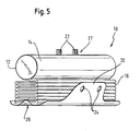
- FIG. 5 shows the air bag module 10 in a state where the air bag cover 12 is folded and the fixing tabs 20 are aligned so that they can be passed around the air bag module 10 on opposite sides.
- the airbag module shown in FIG. 5 shows a variant of the airbag module shown in FIGS. 1 to 4, in which the fixing lugs 20 do not completely cover the lateral surface of the gas generator 14.
- the plane symmetrical airbag cover 12 is folded along the symmetry axis S, so that the two airbag cover halves come to coincide.
- the free sides of the airbag sleeve 12 are connected to each other by means of the seam 34, wherein the seam 34 is interrupted in sections on the projection 32 for the formation of the exhaust opening.
- the seam portion which is opposite to the axis of symmetry S, forms the connection region 26, which separates the fixing lugs 20 from the airbag sheath.
- the distance between the connection region 26 and the suspension holes 24 is selected such that the fixing lugs 20 can be suspended in the fastening sections 22 via the folded, compressible airbag cover 12.
- the gas generator 14 is inserted into the air bag cover 12 via a mounting opening, not shown, and the fastening sections 22 of the gas generator 14 are guided by the mounting holes 30.
- the airbag cover 12 is folded in a Z-shape with a folding direction parallel to the longitudinal axis of the inflator 14, and the fixing tabs 20 are pulled around the fold 16 from the connecting portion 26 in opposite directions to the attachment portion 27.
- the fold 16 is compressed, so that the Ein vonlöcher 24 can be suspended in the mounting portions 22 of the gas generator 14.
- the folding 16 is released and the airbag module 10 can be installed at its predetermined position in the motor vehicle.
Landscapes
- Engineering & Computer Science (AREA)
- Mechanical Engineering (AREA)
- Air Bags (AREA)
Claims (17)
- Module de coussin gonflable pour véhicules automobiles comportant une enveloppe repliée (12) du coussin gonflable et un générateur de gaz (14) disposé à l'intérieur de l'enveloppe (12) du coussin gonflable, dans lequel
au moins une patte de fixation (20) reliée à l'enveloppe (12) du coussin gonflable est guidée au moins en partie extérieurement le long du paquet formé par l'enveloppe repliée (12) du coussin gonflable et le générateur de gaz (14) et est fixée au paquet,
caractérisé en ce
qu'au moins deux pattes de fixation (20) sont guidées depuis une zone commune de liaison (26) au niveau de l'enveloppe (12) du coussin gonflable, dans des directions réciproquement opposées, au moins en partie autour du paquet et sont fixés au paquet au niveau d'une zone commune de fixation (27), et que, pour la libération de l'enveloppe repliée (12) du coussin gonflable, lors du gonflage du coussin gonflable, les deux pattes de fixation (20) sont pourvues chacune d'un affaiblissement de matière (28) notamment sous la forme d'une ligne d'arrachement et/ou de perforations, les deux affaiblissements de matière (28) étant agencés différemment pour la commande du comportement de gonflage de l'enveloppe (12) du coussin gonflable. - Module de coussin gonflable selon la revendication 1, caractérisé en ce que la zone de liaison (26) et la zone de fixation (27) sont situées à l'opposé l'une de l'autre.
- Module de coussin gonflable selon la revendication 1 ou 2, caractérisé en ce
qu'au moins l'une des pattes de fixation (20) est guidée au moins essentiellement complètement autour du paquet. - Module de coussin gonflable selon l'une des revendications précédentes, caractérisé en ce qu'au moins l'une des pattes de fixation (20) est agencée au moins partiellement d'un seul tenant avec l'enveloppe (12) du coussin gonflable.
- Module de coussin gonflable selon l'une des revendications précédentes, caractérisé en ce qu'au moins l'une pattes de fixation (20) comprend une partie de l'enveloppe (12) du coussin gonflable, qui fait saillie au-delà d'une zone de liaison (26), qui délimite l'intérieur de l'enveloppe (12) du coussin gonflable et est formée notamment par la ligne de joint (34).
- Module de coussin gonflable selon l'une des revendications précédentes, caractérisé en ce
qu'au moins l'une des pattes de fixation (20) est équipée, en rapport avec l'enveloppe (12) du coussin gonflable, d'au moins une couche de matériau supplémentaire et/ou différente. - Module de coussin gonflable selon l'une des revendications précédentes, caractérisé en ce qu'au moins l'une des pattes de fixation (20) est fixée, dans la zone de son extrémité libre, au paquet.
- Module de coussin gonflable selon l'une des revendications précédentes, caractérisé en ce
qu'au moins l'une des pattes de fixation (20) est fixée au générateur de gaz (14), notamment à une partie de fixation (22) du générateur de gaz (14), qui fait saillie hors de l'enveloppe (12) du coussin gonflable, de préférence la partie de fixation (22) du générateur de gaz (14) étant conçue en outre pour la fixation du module sur le véhicule automobile. - Module de coussin gonflable selon l'une des revendications précédentes, caractérisé en ce
qu'au moins l'une des pattes de fixation (20) est fixée au paquet par accrochage. - Module de coussin gonflable selon l'une des revendications précédentes, caractérisé en ce
que, pour la fixation d'au moins une patte de fixation (20) au paquet, notamment pour l'accrochage à au moins une partie de fixation (22) du générateur de gaz (14), qui fait saillie hors de l'enveloppe (12) du coussin gonflable, l'enveloppe repliée (12) du coussin gonflable peut être comprimée au-delà d'un degré défini lorsque la patte de fixation (20) est fixée. - Module de coussin gonflable selon l'une des revendications précédentes, caractérisé en ce
que les pattes de fixation (20) sont guidées autour de faces extérieures du paquet, au moins partiellement différentes. - Procédé pour fabriquer un module de coussin gonflable pour véhicules automobiles, notamment selon l'une des revendications précédentes, selon lequel on forme un paquet constitué par une enveloppe repliée (12) du coussin gonflable et un générateur de gaz (14) disposé à l'intérieur de l'enveloppe (12) du coussin gonflable, et on guide une patte de fixation (20) reliée à l'enveloppe (12) du coussin gonflable, au moins en partie à l'extérieur le long du paquet et on la fixe au paquet,
caractérisé en ce
que le comportement de gonflage de l'enveloppe (20) du coussin gonflable est prédéterminé par un agencement différent d'affaiblissements de matière (28), qui sont prévus dans au moins deux pattes de fixation (20), notamment sous la forme de lignes d'arrachement et/ou de perforations. - Procédé selon la revendication 12, caractérisé en ce
qu'au moins l'une des pattes de fixation (20) est formée, pendant la fabrication de l'enveloppe (12) du coussin gonflable, sous la forme d'une partie de l'enveloppe (12) du coussin gonflable, qui fait saillie au-delà d'une zone de liaison (26) entre la patte de fixation (20) et une partie de l'enveloppe, qui délimite l'intérieur de l'enveloppe (12) du coussin gonflable. - Procédé selon la revendication 12 ou 13,
caractérisé en ce qu'au moins l'une des pattes de fixation (20) est équipée, en rapport avec l'enveloppe (12) du coussin gonflable, au moins d'une couche de matériau supplémentaire et/ou différente. - Procédé selon l'une des revendications 12 à 14,
caractérisé en ce
qu'on accroche au moins l'une des pattes de fixation (20), dans la zone de son extrémité libre, à au moins une partie de fixation (22) du générateur de gaz (14), qui fait saillie hors de l'enveloppe (12) du coussin gonflable. - Procédé selon l'une des revendications 12 à 15, caractérisé en ce que les pattes de fixation (20) sont guidées autour de faces extérieures différentes du paquet.
- Procédé selon l'une des revendications 12 à 16,
caractérisé en ce
que l'enveloppe repliée (12) du coussin gonflable et au moins l'une des pattes de fixation (20) sont accordées l'une sur l'autre de telle sorte que l'enveloppe repliée (12) du coussin gonflable peut être comprimée, pour l'accrochage de la patte de fixation (20), au-delà d'un degré déterminé lorsque la patte de fixation (20) est accrochée.
Priority Applications (2)
| Application Number | Priority Date | Filing Date | Title |
|---|---|---|---|
| EP20030020893 EP1514745B1 (fr) | 2003-09-15 | 2003-09-15 | Module de sac gonflable |
| DE50302407T DE50302407D1 (de) | 2003-09-15 | 2003-09-15 | Luftsackmodul |
Applications Claiming Priority (1)
| Application Number | Priority Date | Filing Date | Title |
|---|---|---|---|
| EP20030020893 EP1514745B1 (fr) | 2003-09-15 | 2003-09-15 | Module de sac gonflable |
Publications (2)
| Publication Number | Publication Date |
|---|---|
| EP1514745A1 EP1514745A1 (fr) | 2005-03-16 |
| EP1514745B1 true EP1514745B1 (fr) | 2006-02-15 |
Family
ID=34130213
Family Applications (1)
| Application Number | Title | Priority Date | Filing Date |
|---|---|---|---|
| EP20030020893 Expired - Lifetime EP1514745B1 (fr) | 2003-09-15 | 2003-09-15 | Module de sac gonflable |
Country Status (2)
| Country | Link |
|---|---|
| EP (1) | EP1514745B1 (fr) |
| DE (1) | DE50302407D1 (fr) |
Families Citing this family (9)
| Publication number | Priority date | Publication date | Assignee | Title |
|---|---|---|---|---|
| JP4870210B2 (ja) * | 2006-06-16 | 2012-02-08 | オートリブ ディベロップメント エービー | エアバッグ用ハウジングにおける改善、またはエアバッグ用ハウジングに関する改善 |
| DE102007022974B4 (de) * | 2007-05-14 | 2012-08-30 | Autoliv Development Ab | Gassackmodul |
| DE202007007245U1 (de) | 2007-05-21 | 2007-08-02 | Takata-Petri Ag | Unter Vakuum in Folie verpackter Airbag |
| DE102008029810B4 (de) * | 2008-06-24 | 2025-11-06 | Zf Automotive Germany Gmbh | Optimierte Kniegassack-Faltung |
| DE102008036353B4 (de) | 2008-08-05 | 2016-05-12 | Autoliv Development Ab | Gassackeinrichtung |
| DE102010002261B4 (de) * | 2010-02-23 | 2020-03-19 | Joyson Safety Systems Germany Gmbh | Gassackvorrichtung für ein Personen-Schutzsystem eines Fahrzeugs und Verfahren zu dessen Herstellung |
| DE102010047090A1 (de) * | 2010-10-01 | 2012-04-05 | Autoliv Development Ab | Gassackmodul für ein Kraftfahrzeug |
| DE102017124581A1 (de) | 2017-10-20 | 2019-04-25 | Dalphi Metal Espana, S.A. | Umhüllung eines gassacks eines fahrzeuginsassen-rückhaltesystems und verfahren zum verpacken eines gassacks in einer umhüllung |
| FR3121096B1 (fr) * | 2021-03-26 | 2025-05-30 | Faurecia Interieur Ind | Module de coussin gonflable comprenant une partie de fixation à un élément structurel de véhicule |
Family Cites Families (7)
| Publication number | Priority date | Publication date | Assignee | Title |
|---|---|---|---|---|
| DE19528754A1 (de) * | 1995-08-04 | 1997-02-06 | Trw Repa Gmbh | Gassack-Rückhaltemodul |
| US5564739A (en) * | 1995-12-07 | 1996-10-15 | Takata, Inc. | Side impact airbag module with soft cover |
| GB2309942B (en) * | 1996-02-07 | 2000-01-19 | Airbags Int Ltd | Improvements in or relating to an air-bag |
| US6612610B1 (en) * | 1998-09-18 | 2003-09-02 | Honda Giken Kogyo Kabushiki Kaisha | Air bag device |
| JP4635293B2 (ja) * | 2000-04-07 | 2011-02-23 | タカタ株式会社 | エアバッグ装置 |
| JP4465872B2 (ja) * | 2000-12-19 | 2010-05-26 | 豊田合成株式会社 | エアバッグ装置 |
| DE20215165U1 (de) * | 2002-10-02 | 2003-02-13 | TRW Occupant Restraint Systems GmbH & Co. KG, 73553 Alfdorf | Gassack und Gassackmodul für ein Fahrzeuginsassen-Schutzsystem |
-
2003
- 2003-09-15 DE DE50302407T patent/DE50302407D1/de not_active Expired - Lifetime
- 2003-09-15 EP EP20030020893 patent/EP1514745B1/fr not_active Expired - Lifetime
Also Published As
| Publication number | Publication date |
|---|---|
| DE50302407D1 (de) | 2006-04-20 |
| EP1514745A1 (fr) | 2005-03-16 |
Similar Documents
| Publication | Publication Date | Title |
|---|---|---|
| DE19848592B4 (de) | Airbag mit Abschirmung | |
| DE10125034B4 (de) | Airbag-Vorrichtung | |
| DE69410716T2 (de) | Aufreissbare Luftsackrückhalteklappe | |
| DE10224726B4 (de) | Airbag-Halteklammer | |
| DE102014015996B4 (de) | Airbagvorrichtung | |
| DE102008029810B4 (de) | Optimierte Kniegassack-Faltung | |
| EP2421727B1 (fr) | Module de sac gonflable avec un trou d'évent adaptive | |
| DE112008003109B4 (de) | Airbagvorrichtung für einen Beifahrersitz | |
| DE69919774T2 (de) | Frontpassagierairbag sowie Faltverfahren hierfür | |
| EP0897837A1 (fr) | Dispositif de protection de choc par coussin gonflable et procédé de pliage d'un coussin gonflable | |
| EP2222517A2 (fr) | Sac gonflable pourvu d'une tubulure de remplissage et dispositif comprenant un sac gonflable et un générateur de gaz | |
| EP1873023A1 (fr) | Agencement de masque à gaz latéral | |
| EP1784321A1 (fr) | Sac a gaz pour la protection de la zone des genoux d'un occupant de vehicule a moteur | |
| EP1514745B1 (fr) | Module de sac gonflable | |
| DE10347205B4 (de) | Befestigung für einen Airbag | |
| WO2006015591A1 (fr) | Systeme d'airbag lateral | |
| DE202006009205U1 (de) | Airbageinrichtung für ein Kraftfahrzeug | |
| WO2018077714A1 (fr) | Module d'airbag | |
| DE102007023816B4 (de) | Gassackmodul | |
| DE19710063B4 (de) | Airbag mit Gaserzeuger | |
| DE102010032016B4 (de) | Gassack mit einem einteiligen, zwei Aufblasstufen definierenden Fangband | |
| DE102019216887B4 (de) | Gassackmodul für ein Kraftfahrzeug | |
| EP1908647B1 (fr) | Module d'airbag | |
| EP3883820B1 (fr) | Module airbag pour un véhicule automobile | |
| DE19705830C1 (de) | Beifahrer-Airbagmodul |
Legal Events
| Date | Code | Title | Description |
|---|---|---|---|
| PUAI | Public reference made under article 153(3) epc to a published international application that has entered the european phase |
Free format text: ORIGINAL CODE: 0009012 |
|
| 17P | Request for examination filed |
Effective date: 20040607 |
|
| AK | Designated contracting states |
Kind code of ref document: A1 Designated state(s): AT BE BG CH CY CZ DE DK EE ES FI FR GB GR HU IE IT LI LU MC NL PT RO SE SI SK TR |
|
| AX | Request for extension of the european patent |
Extension state: AL LT LV MK |
|
| GRAP | Despatch of communication of intention to grant a patent |
Free format text: ORIGINAL CODE: EPIDOSNIGR1 |
|
| GRAS | Grant fee paid |
Free format text: ORIGINAL CODE: EPIDOSNIGR3 |
|
| AKX | Designation fees paid |
Designated state(s): DE FR IT |
|
| GRAA | (expected) grant |
Free format text: ORIGINAL CODE: 0009210 |
|
| AK | Designated contracting states |
Kind code of ref document: B1 Designated state(s): DE FR IT |
|
| REF | Corresponds to: |
Ref document number: 50302407 Country of ref document: DE Date of ref document: 20060420 Kind code of ref document: P |
|
| ET | Fr: translation filed | ||
| PLBE | No opposition filed within time limit |
Free format text: ORIGINAL CODE: 0009261 |
|
| STAA | Information on the status of an ep patent application or granted ep patent |
Free format text: STATUS: NO OPPOSITION FILED WITHIN TIME LIMIT |
|
| 26N | No opposition filed |
Effective date: 20061116 |
|
| PGFP | Annual fee paid to national office [announced via postgrant information from national office to epo] |
Ref country code: FR Payment date: 20100901 Year of fee payment: 8 |
|
| PG25 | Lapsed in a contracting state [announced via postgrant information from national office to epo] |
Ref country code: IT Free format text: LAPSE BECAUSE OF NON-PAYMENT OF DUE FEES Effective date: 20100915 |
|
| REG | Reference to a national code |
Ref country code: DE Ref legal event code: R081 Ref document number: 50302407 Country of ref document: DE Owner name: AUTOLIV DEVELOPMENT AB, SE Free format text: FORMER OWNER: DELPHI TECHNOLOGIES, INC., TROY, MICH., US Effective date: 20110415 |
|
| PGRI | Patent reinstated in contracting state [announced from national office to epo] |
Ref country code: IT Effective date: 20110616 |
|
| REG | Reference to a national code |
Ref country code: FR Ref legal event code: ST Effective date: 20120531 |
|
| PG25 | Lapsed in a contracting state [announced via postgrant information from national office to epo] |
Ref country code: FR Free format text: LAPSE BECAUSE OF NON-PAYMENT OF DUE FEES Effective date: 20110930 |
|
| PGFP | Annual fee paid to national office [announced via postgrant information from national office to epo] |
Ref country code: IT Payment date: 20120905 Year of fee payment: 10 Ref country code: DE Payment date: 20120706 Year of fee payment: 10 |
|
| REG | Reference to a national code |
Ref country code: DE Ref legal event code: R119 Ref document number: 50302407 Country of ref document: DE Effective date: 20140401 |
|
| PG25 | Lapsed in a contracting state [announced via postgrant information from national office to epo] |
Ref country code: IT Free format text: LAPSE BECAUSE OF NON-PAYMENT OF DUE FEES Effective date: 20130915 Ref country code: DE Free format text: LAPSE BECAUSE OF NON-PAYMENT OF DUE FEES Effective date: 20140401 |