EP1514745B1 - Airbag module - Google Patents
Airbag module Download PDFInfo
- Publication number
- EP1514745B1 EP1514745B1 EP20030020893 EP03020893A EP1514745B1 EP 1514745 B1 EP1514745 B1 EP 1514745B1 EP 20030020893 EP20030020893 EP 20030020893 EP 03020893 A EP03020893 A EP 03020893A EP 1514745 B1 EP1514745 B1 EP 1514745B1
- Authority
- EP
- European Patent Office
- Prior art keywords
- airbag
- envelope
- fixing
- accordance
- package
- Prior art date
- Legal status (The legal status is an assumption and is not a legal conclusion. Google has not performed a legal analysis and makes no representation as to the accuracy of the status listed.)
- Expired - Lifetime
Links
- 239000000463 material Substances 0.000 claims description 21
- 238000004519 manufacturing process Methods 0.000 claims description 11
- 238000000034 method Methods 0.000 claims description 9
- 230000015572 biosynthetic process Effects 0.000 claims description 3
- 230000003313 weakening effect Effects 0.000 description 13
- 239000000725 suspension Substances 0.000 description 4
- 230000001419 dependent effect Effects 0.000 description 2
- 238000009958 sewing Methods 0.000 description 2
- 230000006835 compression Effects 0.000 description 1
- 238000007906 compression Methods 0.000 description 1
- 230000009977 dual effect Effects 0.000 description 1
- 239000004744 fabric Substances 0.000 description 1
- 230000006870 function Effects 0.000 description 1
- 238000009434 installation Methods 0.000 description 1
- 230000009993 protective function Effects 0.000 description 1
Images


Classifications
-
- B—PERFORMING OPERATIONS; TRANSPORTING
- B60—VEHICLES IN GENERAL
- B60R—VEHICLES, VEHICLE FITTINGS, OR VEHICLE PARTS, NOT OTHERWISE PROVIDED FOR
- B60R21/00—Arrangements or fittings on vehicles for protecting or preventing injuries to occupants or pedestrians in case of accidents or other traffic risks
- B60R21/02—Occupant safety arrangements or fittings, e.g. crash pads
- B60R21/16—Inflatable occupant restraints or confinements designed to inflate upon impact or impending impact, e.g. air bags
- B60R21/20—Arrangements for storing inflatable members in their non-use or deflated condition; Arrangement or mounting of air bag modules or components
- B60R21/217—Inflation fluid source retainers, e.g. reaction canisters; Connection of bags, covers, diffusers or inflation fluid sources therewith or together
- B60R21/2176—Inflation fluid source retainers, e.g. reaction canisters; Connection of bags, covers, diffusers or inflation fluid sources therewith or together the air bag components being completely enclosed in a soft or semi-rigid housing or cover
-
- B—PERFORMING OPERATIONS; TRANSPORTING
- B60—VEHICLES IN GENERAL
- B60R—VEHICLES, VEHICLE FITTINGS, OR VEHICLE PARTS, NOT OTHERWISE PROVIDED FOR
- B60R21/00—Arrangements or fittings on vehicles for protecting or preventing injuries to occupants or pedestrians in case of accidents or other traffic risks
- B60R21/02—Occupant safety arrangements or fittings, e.g. crash pads
- B60R21/16—Inflatable occupant restraints or confinements designed to inflate upon impact or impending impact, e.g. air bags
- B60R21/20—Arrangements for storing inflatable members in their non-use or deflated condition; Arrangement or mounting of air bag modules or components
- B60R21/201—Packaging straps or envelopes for inflatable members
-
- B—PERFORMING OPERATIONS; TRANSPORTING
- B60—VEHICLES IN GENERAL
- B60R—VEHICLES, VEHICLE FITTINGS, OR VEHICLE PARTS, NOT OTHERWISE PROVIDED FOR
- B60R21/00—Arrangements or fittings on vehicles for protecting or preventing injuries to occupants or pedestrians in case of accidents or other traffic risks
- B60R21/02—Occupant safety arrangements or fittings, e.g. crash pads
- B60R21/16—Inflatable occupant restraints or confinements designed to inflate upon impact or impending impact, e.g. air bags
- B60R21/20—Arrangements for storing inflatable members in their non-use or deflated condition; Arrangement or mounting of air bag modules or components
- B60R21/215—Arrangements for storing inflatable members in their non-use or deflated condition; Arrangement or mounting of air bag modules or components characterised by the covers for the inflatable member
- B60R2021/21525—Arrangements for storing inflatable members in their non-use or deflated condition; Arrangement or mounting of air bag modules or components characterised by the covers for the inflatable member the lid being fixed on the bag, or forming part of the bag wall, or the bag itself being used as wall liner
Definitions
- the invention relates to an airbag module for motor vehicles with a folded airbag cover and a gas generator arranged inside the airbag cover and a method for producing an airbag module for motor vehicles.
- Airbag modules in a motor vehicle for the protection of occupants in the event of a collision accident and corresponding methods for producing airbag modules are known in principle.
- US 6612610 B1 discloses an airbag module according to the preamble of claim 1 having at least one fixing flap connected to the airbag cover, which is guided at least partially outside on the package formed by the folded airbag cover and the gas generator and fastened to the package.
- a folded airbag envelope is accommodated with a gas generator arranged inside the airbag envelope in a housing.
- the housing serves, on the one hand, to protect the airbag cover from damage and, on the other hand, to hold together a package formed from the folded airbag cover and the gas generator.
- the housing may be, for example, a rigid box or be formed like a stocking.
- the disadvantage of housing the airbag cover and gas generator in a housing is that an additional operation is required for the introduction of the airbag cover and gas generator into the housing for the production of the overall arrangement.
- a stocking-like housing it is also disadvantageous that the folded airbag can be difficult to be introduced into the flexible housing.
- the solution of this object is achieved by the features of the characterizing part of claim 1, and in particular by the fact that at least two Fixierlappen are each provided with a material weakening, wherein the material weakenings are designed to control the inflation of the airbag cover differently.
- the package With the help of the fixing lobe, the package can be held together, so that the thus formed airbag module can be installed in this form at a predetermined position in the motor vehicle. Since no separate housing is required in this form of air bag module, the number of components is reduced and the air bag module can be space-saving, easy and inexpensive to produce. In addition, the wrapping of the package designed much easier than the necessary according to the prior art introduction of the package in a separate housing with a fixed predetermined internal volume. Overall, therefore, the entire manufacturing process can be carried out much more economically.
- fixation flap in the context of the invention not only a flat lobe-like structure is to be understood, but that fall under the term Fixierlappen other training such as narrow band-like or net-like structure.
- the fixing lugs may be at least substantially completely guided around the package, so that the fixing lugs can additionally assume the protective function of a hitherto conventional housing.
- the fixing lug may be sewn to the airbag envelope, but it may also be formed according to an advantageous embodiment, at least partially integral with the airbag envelope, which further simplifies the manufacturing process.
- the fixation flap can be produced by sewing the airbag cover so that the fixation flap can, according to an advantageous embodiment, comprise a section of the airbag cover which protrudes beyond a connection area delimiting the interior of the airbag cover, in particular formed by the seam. Since the sewing of the airbag envelope can generally be accomplished easily, thus, the production of the airbag module can be further simplified.
- the fixing flap may be provided with at least one additional and / or different material layer with respect to the airbag envelope.
- the fixation flap can be reinforced by an additional layer of material in order to make the fixation flap stiffer and / or firmer compared to the airbag cover, so that improved protection of the folded airbag cover, for example against mechanical damage, is provided.
- fixation flap in the region of its free end to the packet after the airbag module has been wrapped by the fixation flap.
- the package can be easily and permanently arrange within the Fixierlappens.
- the fixing lugs can be fastened in particular with its free end on the gas generator, preferably on at least one attachment section projecting out of the airbag envelope the gas generator, wherein, for example, this attachment portion of the gas generator can also be formed for attachment of the module to the motor vehicle.
- the attachment portion of the inflator can take on a dual function, namely on the one hand fixing the Fixierlappens after wrapping the package through the Fixierlappen and on the other hand attaching the air bag module to the motor vehicle. For fixing the Fixierlappens thus no additional fasteners are needed.
- the attachment portion of the inflator may be formed, for example, as a threaded bolt assembly projecting outwardly beyond the package so that the airbag module may be easily secured to the motor vehicle, such as a seat frame, via a threaded bolt / nut connection.
- fastening holes can be provided at the free ends of the fixing lug, for example, which can be suspended in the fastening sections of the gas generator designed as bolts.
- the folded air bag cover in particular for hanging in at least one of the air bag envelope protruding mounting portion of the inflator can be compressible beyond a given fixed fixing lugs degree. Due to this compressibility, the fixing lug can be pulled over the fastening section of the gas generator without too much effort and hung there.
- the fixation flap Once the fixation flap has been hooked in, the compression of the airbag cover is reduced to the degree that passes through the attached fixation flap is predetermined.
- the fixation flap can be fastened in this way in a particularly simple manner if the airbag cover has a Z-fold.
- the air bag shell goes back automatically due to the restoring force of the spring-like Z-fold to the extent that is determined by the attached Fixierlappen, while holding the air bag module under tension, so that the Fixierlappen not without effort from the mounting portion can solve.
- the fixing flap may be provided with a material weakening, in particular in the form of a tear seam and / or perforation.
- the material weakening can be produced, for example, with the aid of a laser and attached at any point of the fixing lobe.
- the weakening of the material should be applied to the fixation flap such that in the event of release of the air bag wrap, if the fixation flap is torn, a large portion of the torn fixation flap may become caught on the attachment portion while only a small portion of the torn fixation flap is entrained with the air bag wrap becomes.
- the material weakening of a fixing flap can be stronger than the material weakening of the other Fixierlappens be formed so that in the case of inflation of the air envelope first the fixation flap with the stronger material weakening breaks, so that the airbag cover, as long as the Fixierlappen is not torn with the weaker material weakening, initially only in one direction can develop.
- Another object of the invention is a method for producing an airbag module for motor vehicles, in which a package of a folded airbag shell and a gas bag inside the envelope arranged gas generator is formed, and a connected to the airbag sheath Fixierlappen out at least partially outside of the package and along the Package is attached.
- the method according to the invention causes the production of an airbag to be simplified and the costs for producing an airbag are reduced, without restricting the performance of the airbag module.
- FIG. 1 shows an inventive airbag module 10 with an airbag cover 12 in which a cylindrical gas generator 14 is arranged, which is not directly visible in FIG. 1, since it is covered by the airbag cover 12.
- the reference numeral 14 therefore in Fig. 1, only the position of the gas generator is designated within the airbag shell 12.
- the airbag cover 12 has a Z-like fold 16 whose fold lines are aligned parallel to the axis of the cylindrical gas generator 14.
- the folded air bag cover 12 and the gas generator 14 form a package which is completely covered by two fixing tabs 20, wherein the fixing tabs 20 overlap outside of the package in the region of the gas generator 14.
- two fastening sections 22 are each arranged in the form of a threaded bolt in the region of the gas generator 14, in which the Fixierlappen 20 from opposite sides by means of two suspension holes 24 which at their are formed free end, are hung.
- the air bag cover 12 and the fixing tabs 20 are integrally made of a fabric material.
- FIG. 2 shows a cross section through the end face of the airbag module 10 according to the invention.
- the inflator 14 is disposed within the closed air bag cover 12 and welded to the attachment section 22 which extends outwardly from the interior of the air bag cover 12 through the air bag cover 12.
- the lateral surface of the gas generator 14 is substantially completely covered by a part of the airbag envelope 12.
- the part of the airbag cover 12 that does not cover the gas generator 14 is formed as a flattened and folded tube that terminates in a connection region 26 on the opposite side of the gas generator 14.
- two fixing lugs 20 are arranged on the connecting region 26, which are guided around the airbag cover 12, starting from the connection region 26 in opposite directions.
- the airbag module 10 If the airbag module 10 is activated, gas flows out of the gas generator 14 and inflates the airbag cover 12. As soon as the airbag cover 12 is inflated to the extent that it exerts sufficient force on the fixing tabs 20, first the tear seam 28 ruptures with the greater weakening of the material and the airbag cover 12 can deploy in the direction predetermined by the torn fixation tab. Since the airbag cover 12 continues to expand, now also tears the tear seam 28 with the less material weakening and the air bag cover 12 can fully unfold. The larger sections 20a of the torn fixation tabs 20 remain hanging on the attachment section 22, while the other, smaller sections 20b of the torn fixation tabs 20 remain on the airbag cover 12 and are carried along with the airbag cover 12.
- a spread blank of an air bag cover 12 prior to making the air bag module 10 is shown.
- the airbag shell 12 has two symmetrical halves, wherein in the symmetry axis S two spaced mounting holes 30 are formed.
- two respective hanging holes 24 are mounted on a line with the mounting holes 30 substantially parallel to the axis of symmetry S.
- a tear seam 28 is formed in a region between the attachment holes 30 and the suspension holes 24 parallel to the axis of symmetry S of the airbag shell 12, with the tear seams 28 being closer to the suspension holes 24 than to the attachment holes 30.
- the tear seams 28 each have a different material weakening on both airbag shell halves, which is produced by means of a laser perforation.
- projections 32 are provided in mirror image to each other for the formation of a blow-out.
- the airbag cover 12 shown in Fig. 3 is shown in the folded state.
- the open sides of the airbag cover 12 are connected by means of a seam 34, so that the airbag cover forms a cover portion which is substantially completely closed, wherein at the projection 32 for the exhaust opening, the seam 34 is recessed.
- the section of the seam 34 running parallel to the axis of symmetry S of the airbag cover 12 forms the connection region 26 which separates the fixing tabs 20 from the airbag cover 12, the tear seams 28 being mounted on the fixing tabs 20 in the vicinity of the connection region 26 ,
- the inflator 14 is inserted into the air bag cover 12 via a mounting hole, not shown, of the air bag cover 12, the attachment portions 22 of the inflator 14 projecting through the mounting holes 30.
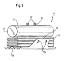
- FIG. 5 shows the air bag module 10 in a state where the air bag cover 12 is folded and the fixing tabs 20 are aligned so that they can be passed around the air bag module 10 on opposite sides.
- the airbag module shown in FIG. 5 shows a variant of the airbag module shown in FIGS. 1 to 4, in which the fixing lugs 20 do not completely cover the lateral surface of the gas generator 14.
- the plane symmetrical airbag cover 12 is folded along the symmetry axis S, so that the two airbag cover halves come to coincide.
- the free sides of the airbag sleeve 12 are connected to each other by means of the seam 34, wherein the seam 34 is interrupted in sections on the projection 32 for the formation of the exhaust opening.
- the seam portion which is opposite to the axis of symmetry S, forms the connection region 26, which separates the fixing lugs 20 from the airbag sheath.
- the distance between the connection region 26 and the suspension holes 24 is selected such that the fixing lugs 20 can be suspended in the fastening sections 22 via the folded, compressible airbag cover 12.
- the gas generator 14 is inserted into the air bag cover 12 via a mounting opening, not shown, and the fastening sections 22 of the gas generator 14 are guided by the mounting holes 30.
- the airbag cover 12 is folded in a Z-shape with a folding direction parallel to the longitudinal axis of the inflator 14, and the fixing tabs 20 are pulled around the fold 16 from the connecting portion 26 in opposite directions to the attachment portion 27.
- the fold 16 is compressed, so that the Ein vonlöcher 24 can be suspended in the mounting portions 22 of the gas generator 14.
- the folding 16 is released and the airbag module 10 can be installed at its predetermined position in the motor vehicle.
Landscapes
- Engineering & Computer Science (AREA)
- Mechanical Engineering (AREA)
- Air Bags (AREA)
Description
Die Erfindung betrifft ein Luftsackmodul für Kraftfahrzeuge mit einer gefalteten Luftsackhülle und einem innerhalb der Luftsackhülle angeordneten Gasgenerator sowie ein Verfahren zur Herstellung eines Luftsackmoduls für Kraftfahrzeuge.The invention relates to an airbag module for motor vehicles with a folded airbag cover and a gas generator arranged inside the airbag cover and a method for producing an airbag module for motor vehicles.
Luftsackmodule in einem Kraftfahrzeug zum Schutz von Insassen bei einem Aufprallunfall und entsprechende Verfahren zur Herstellung von Luftsackmodulen sind grundsätzlich bekannt. US 6612610 B1 z.B offenbart ein Luftsackmodul nach dem Oberbegriff des Anspruchs 1 mit wenigstens einem mit der Luftsackhülle verbundenem Fixierlappen, der zumindest teilweise außen an dem von der gefalteten Luftsackhülle und dem Gasgenerator gebildeten Paket entlang geführt und an dem Paket befestigt ist. Bei bisher bekannten Luftsackmodulen wird eine gefaltete Luftsackhülle mit einem innerhalb der Luftsackhülle angeordneten Gasgenerator in einem Gehäuse untergebracht. Das Gehäuse dient zum einen dazu, die Luftsackhülle vor Beschädigungen zu schützen und zum anderen dazu, ein aus der gefalteten Luftsackhülle und dem Gasgenerator gebildetes Paket zusammenzuhalten. Bei bisher bekannten Luftsackmodulen kann das Gehäuse beispielsweise ein starrer Kasten sein oder strumpfartig ausbildet sein. Der Nachteil an der Unterbringung von Luftsackhülle und Gasgenerator in einem Gehäuse besteht darin, dass für die Herstellung der Gesamtanordnung ein zusätzlicher Arbeitsschritt für das Einbringen von Luftsackhülle und Gasgenerator in das Gehäuse benötigt wird. Bei einem strumpfartigen Gehäuse ist es zudem von Nachteil, dass der gefaltete Luftsack nur schwer in das flexible Gehäuse eingebracht werden kann.Airbag modules in a motor vehicle for the protection of occupants in the event of a collision accident and corresponding methods for producing airbag modules are known in principle. US 6612610 B1, for example, discloses an airbag module according to the preamble of claim 1 having at least one fixing flap connected to the airbag cover, which is guided at least partially outside on the package formed by the folded airbag cover and the gas generator and fastened to the package. In previously known airbag modules, a folded airbag envelope is accommodated with a gas generator arranged inside the airbag envelope in a housing. The housing serves, on the one hand, to protect the airbag cover from damage and, on the other hand, to hold together a package formed from the folded airbag cover and the gas generator. In hitherto known air bag modules, the housing may be, for example, a rigid box or be formed like a stocking. The disadvantage of housing the airbag cover and gas generator in a housing is that an additional operation is required for the introduction of the airbag cover and gas generator into the housing for the production of the overall arrangement. In a stocking-like housing, it is also disadvantageous that the folded airbag can be difficult to be introduced into the flexible housing.
Es ist Aufgabe der vorliegenden Erfindung, ein Luftsackmodul bereitzustellen, das Platz sparend, kostengünstig und einfach herzustellen ist, ohne die Leistungsfähigkeit des Luftsackmoduls einzuschränken.It is an object of the present invention to provide an airbag module that is space-saving, inexpensive and easy to manufacture without compromising the performance of the airbag module.
Es ist eine weitere Aufgabe der Erfindung die Entfaltungsrichtung des Luftsacks zu steuern, was beispielsweise bei bestimmten Einbauorten des Luftsackmoduls im Kraftfahrzeug oder bei der OOP-Problematik (Outof position-Problematik) vorteilhaft sein kann. Die Lösung dieser Aufgabe erfolgt durch die Merkmale des kennzeichnenden Teils des Anspruchs 1, und insbesondere dadurch dass wenigstens zwei Fixierlappen jeweils mit einer Materialschwächung versehen sind, wobei die Materialschwächungen zur Steuerung des Aufblasverhaltens der Luftsackhülle unterschiedlich ausgeführt sind.It is a further object of the invention to control the deployment direction of the airbag, which may be advantageous, for example, in certain installation locations of the airbag module in the motor vehicle or in the OOP problem (Outof position problem). The solution of this object is achieved by the features of the characterizing part of claim 1, and in particular by the fact that at least two Fixierlappen are each provided with a material weakening, wherein the material weakenings are designed to control the inflation of the airbag cover differently.
Mit Hilfe des Fixierlappens kann das Paket zusammengehalten werden, so dass das so ausgebildete Luftsackmodul in dieser Form an einer vorbestimmten Position im Kraftfahrzeug eingebaut werden kann. Da bei dieser Form des Luftsackmoduls kein separates Gehäuse benötigt wird, wird die Anzahl der Bauteile reduziert und das Luftsackmodul lässt sich Platz sparend, einfach und kostengünstig herstellen. Zudem gestaltet sich das Umwickeln des Pakets deutlich einfacher als das gemäß Stand der Technik nötige Einbringen des Pakets in ein separates Gehäuse mit einem fest vorgegebenen Innenvolumen. Insgesamt lässt sich also der gesamte Herstellungsprozess deutlich wirtschaftlicher durchführen.With the help of the fixing lobe, the package can be held together, so that the thus formed airbag module can be installed in this form at a predetermined position in the motor vehicle. Since no separate housing is required in this form of air bag module, the number of components is reduced and the air bag module can be space-saving, easy and inexpensive to produce. In addition, the wrapping of the package designed much easier than the necessary according to the prior art introduction of the package in a separate housing with a fixed predetermined internal volume. Overall, therefore, the entire manufacturing process can be carried out much more economically.
Es sei angemerkt, dass unter Fixierlappen im Sinne der Erfindung nicht nur ein flächiges lappenartiges Gebilde zu verstehen ist, sondern dass unter den Begriff Fixierlappen auch andere Ausbildungen wie beispielsweise schmale bandartige oder auch netzartige Gebilde fallen.It should be noted that the term fixation flap in the context of the invention not only a flat lobe-like structure is to be understood, but that fall under the term Fixierlappen other training such as narrow band-like or net-like structure.
Vorteilhafte Ausführungsformen der Erfindung sind in der Beschreibung, den Figuren sowie den Unteransprüchen beschrieben.Advantageous embodiments of the invention are described in the description, the figures and the subclaims.
Gemäß einer vorteilhaften Ausführungsform kann der Fixierlappen zumindest im Wesentlichen vollständig um das Paket herum geführt sein, so dass der Fixierlappen zusätzlich die Schutzfunktion eines bisher üblichen Gehäuses übernehmen kann.According to an advantageous embodiment, the fixing lugs may be at least substantially completely guided around the package, so that the fixing lugs can additionally assume the protective function of a hitherto conventional housing.
Der Fixierlappen kann an der Luftsackhülle angenäht sein, allerdings kann er auch gemäß einer vorteilhaften Ausführungsform zumindest teilweise einstückig mit der Luftsackhülle ausgebildet sein, was den Herstellungsprozess zusätzlich vereinfacht.The fixing lug may be sewn to the airbag envelope, but it may also be formed according to an advantageous embodiment, at least partially integral with the airbag envelope, which further simplifies the manufacturing process.
Beispielsweise kann der Fixierlappen durch Abnähen der Luftsackhülle hergestellt sein, so dass der Fixierlappen gemäß einer vorteilhaften Ausführungsform einen Abschnitt der Luftsackhülle umfassen kann, der über einen das Innere der Luftsackhülle begrenzenden, insbesondere von der Naht gebildeten Verbindungsbereich hinaus vorsteht. Da sich das Abnähen der Luftsackhülle im Allgemeinen einfach bewerkstelligen lässt, kann somit die Herstellung des Luftsackmoduls noch weiter vereinfacht werden.For example, the fixation flap can be produced by sewing the airbag cover so that the fixation flap can, according to an advantageous embodiment, comprise a section of the airbag cover which protrudes beyond a connection area delimiting the interior of the airbag cover, in particular formed by the seam. Since the sewing of the airbag envelope can generally be accomplished easily, thus, the production of the airbag module can be further simplified.
Bei einer vorteilhaften Ausführungsform kann der Fixierlappen in Bezug auf die Luftsackhülle mit wenigstens einer zusätzlichen und/oder unterschiedlichen Materiallage versehen sein. So kann beispielsweise der Fixierlappen durch eine zusätzliche Materiallage verstärkt sein, um den Fixierlappen im Vergleich zur Luftsackhülle steifer und/oder fester auszubilden, so dass ein verbesserter Schutz der gefalteten Luftsackhülle beispielsweise gegen mechanische Beschädigungen gegeben ist.In an advantageous embodiment, the fixing flap may be provided with at least one additional and / or different material layer with respect to the airbag envelope. Thus, for example, the fixation flap can be reinforced by an additional layer of material in order to make the fixation flap stiffer and / or firmer compared to the airbag cover, so that improved protection of the folded airbag cover, for example against mechanical damage, is provided.
Es ist möglich, den Fixierlappen im Bereich seines freien Endes an dem Paket zu befestigen, nachdem das Luftsackmodul durch den Fixierlappen umwickelt wurde. So lässt sich das Paket einfach und dauerhaft innerhalb des Fixierlappens anordnen.It is possible to fix the fixation flap in the region of its free end to the packet after the airbag module has been wrapped by the fixation flap. Thus, the package can be easily and permanently arrange within the Fixierlappens.
Bei einer vorteilhaften Ausführungsform kann der Fixierlappen insbesondere mit seinem freien Ende am Gasgenerator befestigt sein, bevorzugt an wenigstens einem aus der Luftsackhülle heraus ragenden Befestigungsabschnitt des Gasgenerators, wobei z.B. dieser Befestigungsabschnitt des Gasgenerators außerdem zur Befestigung des Moduls am Kraftfahrzeug ausgebildet werden kann. Somit kann der Befestigungsabschnitt des Gasgenerators eine Doppelfunktion übernehmen, nämlich zum einen das Befestigen des Fixierlappens nach dem Einwickeln des Pakets durch den Fixierlappen und zum anderen das Befestigen des Luftsackmoduls am Kraftfahrzeug. Zum Befestigen des Fixierlappens werden somit keine zusätzlichen Befestigungselemente benötigt.In an advantageous embodiment, the fixing lugs can be fastened in particular with its free end on the gas generator, preferably on at least one attachment section projecting out of the airbag envelope the gas generator, wherein, for example, this attachment portion of the gas generator can also be formed for attachment of the module to the motor vehicle. Thus, the attachment portion of the inflator can take on a dual function, namely on the one hand fixing the Fixierlappens after wrapping the package through the Fixierlappen and on the other hand attaching the air bag module to the motor vehicle. For fixing the Fixierlappens thus no additional fasteners are needed.
Der Befestigungsabschnitt des Gasgenerators kann beispielsweise als eine nach außen über das Paket hervorstehende Gewindebolzenanordnung ausgebildet sein, so dass das Luftsackmodul über eine Gewindebolzen/Mutter-Verbindung am Kraftfahrzeug, beispielsweise an einem Sitzrahmen, einfach befestigt werden kann.The attachment portion of the inflator may be formed, for example, as a threaded bolt assembly projecting outwardly beyond the package so that the airbag module may be easily secured to the motor vehicle, such as a seat frame, via a threaded bolt / nut connection.
Wenn der Fixierlappen gemäß einer vorteilhaften Ausführungsform an dem Paket durch Einhängen befestigt wird, können beispielsweise an den freien Enden des Fixierlappens Befestigungslöcher vorgesehen sein, die in die als Bolzen ausgebildete Befestigungsabschnitte des Gasgenerators eingehängt werden können.If, according to an advantageous embodiment, the fixing lug is fastened to the package by hanging, fastening holes can be provided at the free ends of the fixing lug, for example, which can be suspended in the fastening sections of the gas generator designed as bolts.
Um den Fixierlappen an dem Paket einfach befestigen und sicher halten zu können, kann die gefaltete Luftsackhülle, insbesondere zum Einhängen in wenigstens einen aus der Luftsackhülle heraus ragenden Befestigungsabschnitt des Gasgenerators, über ein bei befestigtem Fixierlappen gegebenes Maß hinaus komprimierbar sein. Durch diese Komprimierbarkeit kann der Fixierlappen ohne allzu großen Kraftaufwand über den Befestigungsabschnitt des Gasgenerators gezogen und dort eingehängt werden. Ist der Fixierlappen eingehängt, wird die Komprimierung der Luftsackhülle auf das Maß zurückgeführt, das durch den befestigten Fixierlappen vorgegeben ist. Besonders einfach kann der Fixierlappen auf diese Art befestigen werden, wenn die Luftsackhülle eine Z-Faltung aufweist. Nachdem der Fixierlappen eingehängt ist, geht die Luftsackhülle aufgrund der Rückstellkraft der federartigen Z-Faltung selbsttätig auf das Maß zurück, das durch den befestigten Fixierlappen vorgegeben ist, und hält dabei das Luftsackmodul unter Spannung, so dass sich der Fixierlappen nicht ohne Kraftaufwand von dem Befestigungsabschnitt lösen kann.In order to easily attach the fixation tabs on the package and keep safe, the folded air bag cover, in particular for hanging in at least one of the air bag envelope protruding mounting portion of the inflator can be compressible beyond a given fixed fixing lugs degree. Due to this compressibility, the fixing lug can be pulled over the fastening section of the gas generator without too much effort and hung there. Once the fixation flap has been hooked in, the compression of the airbag cover is reduced to the degree that passes through the attached fixation flap is predetermined. The fixation flap can be fastened in this way in a particularly simple manner if the airbag cover has a Z-fold. After the Fixierlappen is mounted, the air bag shell goes back automatically due to the restoring force of the spring-like Z-fold to the extent that is determined by the attached Fixierlappen, while holding the air bag module under tension, so that the Fixierlappen not without effort from the mounting portion can solve.
Um beim Aufblasen der Luftsackhülle beispielsweise im Falle eines Aufpralls des Kraftfahrzeugs, die gefaltete Luftsackhülle freizugeben, kann der Fixierlappen mit einer Materialschwächung, insbesondere in Form einer Reißnaht und/ oder Perforation versehen sein. Die Materialschwächung kann beispielsweise mit Hilfe eines Lasers hergestellt und an einer beliebigen Stelle des Fixierlappens angebracht sein. Vorteilhafterweise sollte die Materialschwächung an dem Fixierlappen so angebracht sein, dass im Falle der Freigabe der Luftsackhülle, wenn der Fixierlappen gerissen ist, ein großer Abschnitt des zerrissenen Fixierlappens an dem Befestigungsabschnitt hängen bleiben kann, während nur ein kleiner Abschnitt des zerrissenen Fixierlappens mit der Luftsackhülle mitgeführt wird.In order to release the folded airbag cover during inflation of the airbag cover, for example in the event of a collision of the motor vehicle, the fixing flap may be provided with a material weakening, in particular in the form of a tear seam and / or perforation. The material weakening can be produced, for example, with the aid of a laser and attached at any point of the fixing lobe. Advantageously, the weakening of the material should be applied to the fixation flap such that in the event of release of the air bag wrap, if the fixation flap is torn, a large portion of the torn fixation flap may become caught on the attachment portion while only a small portion of the torn fixation flap is entrained with the air bag wrap becomes.
Gemäß einer vorteilhaften Ausführungsform können wenigstens zwei Fixierlappen um zumindest teilweise unterschiedliche Außenseiten des Pakets herum geführt sein. Eine mögliche Ausbildung einer solchen Ausführungsform wird nachfolgend noch anhand der Figuren erläutert. Gemäß einer vorteilhaften Ausführungsform kann die Materialschwächung eines Fixierlappens stärker als die Materialschwächung des anderen Fixierlappens ausgebildet sein, so dass im Falle des Aufblasens der Lufthülle zuerst der Fixierlappen mit der stärkeren Materialschwächung reißt, so dass sich die Luftsackhülle, solange der Fixierlappen mit der schwächeren Materialschwächung noch nicht gerissen ist, zunächst nur in eine Richtung entfalten kann.According to an advantageous embodiment, at least two fixing lugs may be guided around at least partially different outer sides of the package. A possible embodiment of such an embodiment will be explained below with reference to the figures. According to an advantageous embodiment, the material weakening of a fixing flap can be stronger than the material weakening of the other Fixierlappens be formed so that in the case of inflation of the air envelope first the fixation flap with the stronger material weakening breaks, so that the airbag cover, as long as the Fixierlappen is not torn with the weaker material weakening, initially only in one direction can develop.
Weiterer Gegenstand der Erfindung ist ein Verfahren zur Herstellung eines Luftsackmoduls für Kraftfahrzeuge, bei dem ein Paket aus einer gefalteten Luftsackhülle und einem innerhalb der Luftsackhülle angeordneten Gasgenerator gebildet wird, und ein mit der Luftsackhülle verbundener Fixierlappen zumindest teilweise außen an dem Paket entlang geführt und an dem Paket befestigt wird.Another object of the invention is a method for producing an airbag module for motor vehicles, in which a package of a folded airbag shell and a gas bag inside the envelope arranged gas generator is formed, and a connected to the airbag sheath Fixierlappen out at least partially outside of the package and along the Package is attached.
Vorteilhafte Ausführungsformen dieses Verfahrens sind in den vom unabhängigen Verfahrensanspruch abhängigen Unteransprüchen angegeben.Advantageous embodiments of this method are specified in the independent claims dependent dependent claims.
Wie bereits im Zusammenhang mit dem erfindungsgemäßen Luftsackmodul beschrieben wird, bewirkt das erfindungsgemäße Verfahren, dass die Herstellung eines Luftsacks vereinfacht ist und die Kosten zur Herstellung eines Luftsacks reduziert sind, ohne die Leistungsfähigkeit des Luftsackmoduls zu beschränken.As already described in connection with the airbag module according to the invention, the method according to the invention causes the production of an airbag to be simplified and the costs for producing an airbag are reduced, without restricting the performance of the airbag module.
Nachfolgend wird die vorliegende Erfindung rein beispielhaft anhand einer vorteilhaften Ausführungsform unter Bezugnahme auf die beigefügten Zeichnungen beschrieben. Es zeigen:
- Fig. 1
- eine perspektivische Darstellung eines erfindungsgemäßen Luftsackmoduls,
- Fig. 2
- einen schematischen Querschnitt eines erfindungsgemäßen Luftsackmoduls,
- Fig. 3
- die Form einer Luftsackhülle vor der Herstellung des Luftsackmoduls,
- Fig. 4
- die in Fig. 3 dargestellte Luftsackhülle nach dem Zusammenfalten und
- Fig. 5
- eine perspektivische Ansicht eines erfindungsgemäßen Luftsackmoduls vor dem Befestigen der Fixierlappen.
- Fig. 1
- a perspective view of an airbag module according to the invention,
- Fig. 2
- a schematic cross section of an airbag module according to the invention,
- Fig. 3
- the shape of an airbag shell prior to the manufacture of the airbag module,
- Fig. 4
- the airbag sleeve shown in Fig. 3 after folding and
- Fig. 5
- a perspective view of an air bag module according to the invention before attaching the Fixierlappen.
Fig. 1 zeigt ein erfindungsgemäßes Luftsackmodul 10 mit einer Luftsackhülle 12, in der ein zylinderförmiger Gasgenerator 14 angeordnet ist, welcher in Fig. 1 nicht direkt sichtbar ist, da er von der Luftsackhülle 12 verdeckt wird. Mit dem Bezugszeichen 14 ist daher in Fig. 1 lediglich die Position des Gasgenerators innerhalb der Luftsackhülle 12 bezeichnet. Die Luftsackhülle 12 weist eine Z-artige Faltung 16 auf, deren Faltlinien parallel zur Achse des zylinderförmigen Gasgenerators 14 ausgerichtet sind. Die gefaltete Luftsackhülle 12 und der Gasgenerator 14 bilden ein Paket, das durch zwei Fixierlappen 20 vollständig bedeckt ist, wobei sich die Fixierlappen 20 außerhalb des Pakets im Bereich des Gasgenerators 14 überlappen. An der Außenseite der Luftsackhülle 12 sind im Bereich des Gasgenerators 14 zwei Befestigungsabschnitte 22 jeweils in Form eines Gewindebolzens angeordnet, in die die Fixierlappen 20 von entgegengesetzten Seiten mit Hilfe von zwei Einhängelöchern 24, die an ihren freien Ende ausgebildet sind, eingehängt sind. Die Luftsackhülle 12 und die Fixierlappen 20 sind einstückig aus einem Gewebematerial hergestellt.1 shows an
In Fig. 2 ist ein Querschnitt durch die Stirnseite des erfindungsgemäßen Luftsackmoduls 10 gezeigt. Der Gasgenerator 14 ist in der geschlossenen Luftsackhülle 12 angeordnet und mit dem Befestigungsabschnitt 22 verschweißt, der sich vom Inneren der Luftsackhülle 12 nach außen durch die Luftsackhülle 12 erstreckt. Die Mantelfläche des Gasgenerators 14 ist von einem Teil der Luftsackhülle 12 im Wesentlichen vollständig bedeckt. Der Teil der Luftsackhülle 12, der den Gasgenerator 14 nicht bedeckt, ist als ein flach gelegter und gefalteter Schlauch ausgebildet, der in einem Verbindungsbereich 26 an der dem Gasgenerator 14 gegenüberliegenden Seite endet. Außerhalb der Luftsackhülle 12 sind am Verbindungsbereich 26 zwei Fixierlappen 20 angeordnet, die ausgehend vom Verbindungsbereich 26 in entgegengesetzte Richtungen um die Luftsackhülle 12 herumgeführt sind. Die freien Enden der Fixierlappen 20 überlappen sich außerhalb der Luftsackhülle 12 in einem Befestigungsbereich 27, der dem Verbindungsbereich 26 gegenüberliegt, und werden durch die Befestigungsabschnitte 22, die mit dem Gasgenerator 14 verbunden sind, gehalten. An den Fixierlappen 20 sind in der Nähe des Verbindungsbereichs 26 Reißnähte 28 vorgesehen, die wie in Fig. 3 zu sehen ist, unterschiedlich starke Materialschwächungen aufweisen.FIG. 2 shows a cross section through the end face of the
Wird das Luftsackmodul 10 aktiviert, strömt Gas aus dem Gasgenerator 14 und bläst die Luftsackhülle 12 auf. Sobald die Luftsackhülle 12 soweit aufgeblasen ist, dass sie eine ausreichende Kraft auf die Fixierlappen 20 ausübt, reißt zuerst die Reißnaht 28 mit der stärkeren Materialschwächung auf und die Luftsackhülle 12 kann sich in die durch den gerissenen Fixierlappen vorgegebene Richtung entfalten. Da die Luftsackhülle 12 sich immer weiter ausdehnt, reißt nun auch die Reißnaht 28 mit der geringeren Materialschwächung und die Luftsackhülle 12 kann sich vollständig entfalten. Die größeren Teilabschnitte 20a der zerrissenen Fixierlappen 20 bleiben an dem Befestigungsabschnitt 22 hängen, während die anderen, kleineren Teilabschnitte 20b der zerrissenen Fixierlappen 20 an der Luftsackhülle 12 bleiben und mit der Luftsackhülle 12 mitgeführt werden.If the
In Fig. 3 ist ein ausgebreiteter Zuschnitt einer Luftsackhülle 12 vor dem Herstellen des Luftsackmoduls 10 gezeigt. Die Luftsackhülle 12 weist zwei symmetrische Hälften auf, wobei in der Symmetrieachse S zwei im Abstand angeordnete Befestigungslöcher 30 ausgebildet sind. An zwei gegenüberliegenden Seiten der Luftsackhülle 12 sind im Wesentlichen parallel zur Symmetrieachse S jeweils zwei Einhängelöcher 24 auf einer Linie mit den Befestigungslöchern 30 angebracht. Auf jeder Hälfte der Luftsackhülle 12 ist in einem Bereich zwischen den Befestigungslöchern 30 und den Einhängelöchern 24 jeweils parallel zur Symmetrieachse S der Luftsackhülle 12 eine Reißnaht 28 ausgebildet, wobei die Reißnähte 28 näher bei den Einhängelöchern 24 als bei den Befestigungslöchern 30 liegen. Die Reißnähte 28 weisen auf beiden Luftsackhüllenhälften jeweils eine unterschiedliche Materialschwächung auf, die mittels einer Laserperforation hergestellt ist. An beiden Luftsackhüllenhälften sind spiegelbildlich zueinander Vorsprünge 32 für die Ausbildung einer Ausblasöffnung vorgesehen.In Fig. 3, a spread blank of an
In Fig. 4 ist die in Fig. 3 dargestellte Luftsackhülle 12 in zusammengeklappten Zustand gezeigt. Die offenen Seiten der Luftsackhülle 12 sind mittels einer Naht 34 verbunden, so dass die Luftsackhülle einen Hüllenabschnitt bildet, der im Wesentlichen vollständig geschlossen ist, wobei an dem Vorsprung 32 für die Ausblasöffnung die Naht 34 ausgespart ist. An der den Befestigungslöchern 30 bzw. den Befestigungsabschnitten 22 abgewandten Seite der Luftsackhülle 12 bildet der parallel zur Symmetrieachse S der Luftsackhülle 12 verlaufende Abschnitt der Naht 34 den Verbindungsbereich 26 aus, der die Fixierlappen 20 von der Luftsackhülle 12 trennt, wobei die Reißnähte 28 auf den Fixierlappen 20 in der Nähe des Verbindungsbereichs 26 angebracht sind. Der Gasgenerator 14 ist über eine nicht gezeigte Montageöffnung der Luftsackhülle 12 in die Luftsackhülle 12 eingeführt, wobei die Befestigungsabschnitte 22 des Gasgenerators 14 durch die Befestigungslöcher 30 ragen.4, the
Fig. 5 zeigt das Luftsackmodul 10 in einem Zustand, indem die Luftsackhülle 12 gefaltet ist und die Fixierlappen 20 so ausgerichtet sind, dass sie auf gegenüberliegenden Seiten um das Luftsackmodul 10 herumgeführt werden können. Das in Fig. 5 dargestellte Luftsackmodul zeigt eine Variante zu dem in den Fig. 1 bis 4 dargestellten Luftsackmodul, bei der die Fixierlappen 20 die Mantelfläche des Gasgenerators 14 nicht vollständig bedecken.FIG. 5 shows the
Zur Herstellung des Luftsackmoduls 10 gemäß den Fig. 1 bis 5 wird die ebene symmetrische Luftsackhülle 12 entlang der Symmetrieachse S gefaltet, so dass die beiden Luftsackhüllenhälften zur Deckung kommen. Die freien Seiten der Luftsackhülle 12 werden mittels der Naht 34 miteinander verbunden, wobei am Vorsprung 32 zur Ausbildung der Ausblasöffnung die Naht 34 abschnittsweise unterbrochen wird. Der Nahtabschnitt, der der Symmetrieachse S gegenüberliegt, bildet den Verbindungsbereich 26 aus, der die Fixierlappen 20 von der Luftsackhülle trennt. Der Abstand des Verbindungsbereichs 26 zu den Einhängelöchern 24 ist so gewählt, dass die Fixierlappen 20 über die gefaltete, komprimierbare Luftsackhülle 12 in die Befestigungsabschnitte 22 eingehängt werden können. Im nächsten Schritt wird der Gasgenerator 14 über eine nicht gezeigte Montageöffnung in die Luftsackhülle 12 eingeführt und die Befestigungsabschnitte 22 des Gasgenerators 14 werden durch die Befestigungslöcher 30 geführt. Danach wird die Luftsackhülle 12 mit einer Faltrichtung parallel zur Längsachse des Gasgenerators 14 Z-förmig gefaltet, und die Fixierlappen 20 werden ausgehend von dem Verbindungsbereich 26 in entgegengesetzte Richtungen um die Faltung 16 zum Befestigungsbereich 27 herumgezogen. Anschließend wird die Faltung 16 komprimiert, so dass die Einhängelöcher 24 in die Befestigungsabschnitte 22 des Gasgenerators 14 eingehängt werden können. Danach wird die Faltung 16 losgelassen und das Luftsackmodul 10 kann so an seiner vorbestimmten Position im Kraftfahrzeug eingebaut werden.To produce the
- 1010
- LuftsackmodulAir bag module
- 1212
- LuftsackhülleAirbag envelope
- 1414
- Gasgeneratorinflator
- 1616
- Faltungfolding
- 2020
- Fixierlappenfixing tab
- 20a20a
- FixierlappenteilFixierlappenteil
- 20b20b
- FixierlappenteilFixierlappenteil
- 2222
- Befestigungsabschnittattachment section
- 2424
- EinhängelochEinhängeloch
- 2626
- Verbindungsbereichconnecting area
- 2727
- Befestigungsbereichfastening area
- 2828
- Reißnahttear seam
- 3030
- Befestigungslochmounting hole
- 3232
- Vorsprunghead Start
- 3434
- Nahtseam
- SS
- Symmetrieachseaxis of symmetry
Claims (17)
- An airbag module for motor vehicles comprising a folded airbag envelope (12) and a gas generator (14) arranged inside the airbag envelope (12), wherein
at least one fixing flap (20) connected to the airbag envelope (12) is guided at least partly outwardly along the package formed by the folded airbag envelope (12) and by the gas generator (14) and is secured to the package,
characterized in that at least two fixing flaps (20) are guided at least partly around the package in mutually opposite directions, starting from a common connection region (26) at the airbag envelope (12), and are secured to a common securing region (27) at the package; and in that both fixing flaps (20) are each provided with a material weakness (28), in particular in the form of a tearing seam and/or a perforation, to release the folded airbag envelope (12) on the inflation of the airbag, with the two material weaknesses (28) being designed differently to control the inflation behavior of the airbag envelope (12). - An airbag module in accordance with claim 1, characterized in that the connection region (26) and the securing region (27) lie opposite one another
- An airbag module in accordance with claim 1 or claim 2, characterized in that at least one of the fixing flaps (20) is guided at least substantially completely around the package.
- An airbag module in accordance with any one of the preceding claims, characterized in that at least one of the fixing flaps (20) is made at least partly in one piece with the airbag envelope (12).
- An airbag module in accordance with any one of the preceding claims, characterized in that at least one of the fixing flaps (20) includes a section of the airbag envelope (12) which projects beyond a connection region (26) bounding the interior of the airbag envelope (12) and in particular formed by the seam (34).
- An airbag module in accordance with any one of the preceding claims, characterized in that at least one of the fixing flaps (20) is provided with at least one additional and/or different material layer with respect to the airbag envelope (12).
- An airbag module in accordance with any one of the preceding claims, characterized in that at least one of the fixing flaps (20) is secured to the package in the region of the free end of said fixing flap.
- An airbag module in accordance with any one of the preceding claims, characterized in that at least one of the fixing flaps (20) is secured to the gas generator (14), in particular to at least one securing section (22) of the gas generator (14) projecting out of the airbag envelope (12), with the securing section (22) of the gas generator (14) moreover preferably being formed for the securing of the module to the motor vehicle.
- An airbag module in accordance with any one of the preceding claims, characterized in that at least one of the fixing flaps (20) is secured to the package by being hung into place.
- An airbag module in accordance with any one of the preceding claims, characterized in that the folded airbag envelope (12) can be compressed beyond a dimension given when the fixing flap (20) is secured to secure at least one fixing flap (20) to the package, in particular for hanging into place into at least one securing section (22) of the gas generator (14) projecting out of the airbag envelope (12).
- An airbag module in accordance with any one of the preceding claims, characterized in that the fixing flaps (20) are guided around at least partly different outer sides of the package.
- A method for the manufacture of an airbag module for motor vehicles, in particular in accordance with any one of the preceding claims, in which a package is formed from a folded airbag (12) and from a gas generator (14) arranged inside the airbag envelope (12) and a fixing flap (20) connected to the airbag envelope (12) is guided at least partly outwardly along the package and is secured to the package,
characterized in that
the inflation behavior of the airbag envelope (20) is pre-determined by a different formation of material weaknesses (28) which are provided in at least two fixing flaps (20), in particular in the form of tearing seams and/or perforations. - A method in accordance with claim 12, characterized in that at least one of the fixing flaps (20) is made during the manufacture of the airbag envelope (12) as a section of the airbag envelope (12) which projects beyond a connection region (26) between the fixing flap (20) and an envelope section bounding the interior of the airbag envelope (12).
- A method in accordance with claim 13 or claim 14, characterized in that at least one of the fixing flaps (20) is provided with at least one additional and/or different material layer with respect to the airbag envelope (12).
- A method in accordance with any one of the claims 12 to 14, characterized in that at least one of the fixing flaps (20) is hung into place in the region of its free end into at least one securing section (22) of the gas generator (14) projecting from the airbag envelope (12).
- A method in accordance with any one of the claims 12 to 15, characterized in that the fixing flaps (20) are guided around different outer sides of the package.
- A method in accordance with any one of the claims 12 to 16, characterized in that the folded airbag envelope (12) and at least one of the fixing flaps (20) are matched to one another such that the folded airbag envelope (12) can be compressed beyond a dimension given when the fixing flap (20) is hung into place, for the hanging into place of the fixing flap (20).
Priority Applications (2)
| Application Number | Priority Date | Filing Date | Title |
|---|---|---|---|
| EP20030020893 EP1514745B1 (en) | 2003-09-15 | 2003-09-15 | Airbag module |
| DE50302407T DE50302407D1 (en) | 2003-09-15 | 2003-09-15 | Air bag module |
Applications Claiming Priority (1)
| Application Number | Priority Date | Filing Date | Title |
|---|---|---|---|
| EP20030020893 EP1514745B1 (en) | 2003-09-15 | 2003-09-15 | Airbag module |
Publications (2)
| Publication Number | Publication Date |
|---|---|
| EP1514745A1 EP1514745A1 (en) | 2005-03-16 |
| EP1514745B1 true EP1514745B1 (en) | 2006-02-15 |
Family
ID=34130213
Family Applications (1)
| Application Number | Title | Priority Date | Filing Date |
|---|---|---|---|
| EP20030020893 Expired - Lifetime EP1514745B1 (en) | 2003-09-15 | 2003-09-15 | Airbag module |
Country Status (2)
| Country | Link |
|---|---|
| EP (1) | EP1514745B1 (en) |
| DE (1) | DE50302407D1 (en) |
Families Citing this family (9)
| Publication number | Priority date | Publication date | Assignee | Title |
|---|---|---|---|---|
| JP4870210B2 (en) * | 2006-06-16 | 2012-02-08 | オートリブ ディベロップメント エービー | Improvements in airbag housings or improvements in airbag housings |
| DE102007022974B4 (en) * | 2007-05-14 | 2012-08-30 | Autoliv Development Ab | Airbag module |
| DE202007007245U1 (en) | 2007-05-21 | 2007-08-02 | Takata-Petri Ag | Airbag package, e.g. to act as a co-driver's airbag in a motor vehicle, has an airbag vacuum-packed in foil and folded into a deep-drawn base foil sealed with a covering foil |
| DE102008029810B4 (en) * | 2008-06-24 | 2025-11-06 | Zf Automotive Germany Gmbh | Optimized knee bag folding |
| DE102008036353B4 (en) | 2008-08-05 | 2016-05-12 | Autoliv Development Ab | Air bag device |
| DE102010002261B4 (en) * | 2010-02-23 | 2020-03-19 | Joyson Safety Systems Germany Gmbh | Airbag device for a personal protection system of a vehicle and method for its production |
| DE102010047090A1 (en) * | 2010-10-01 | 2012-04-05 | Autoliv Development Ab | Airbag module for a motor vehicle |
| DE102017124581A1 (en) | 2017-10-20 | 2019-04-25 | Dalphi Metal Espana, S.A. | PACKAGING A GAS BAG OF A VEHICLE ABSORPTION RESTRAINT SYSTEM AND METHOD FOR PACKAGING A GASSACK IN A PACKAGING |
| FR3121096B1 (en) * | 2021-03-26 | 2025-05-30 | Faurecia Interieur Ind | Airbag module comprising a portion for attachment to a vehicle structural member |
Family Cites Families (7)
| Publication number | Priority date | Publication date | Assignee | Title |
|---|---|---|---|---|
| DE19528754A1 (en) * | 1995-08-04 | 1997-02-06 | Trw Repa Gmbh | Airbag restraint module |
| US5564739A (en) * | 1995-12-07 | 1996-10-15 | Takata, Inc. | Side impact airbag module with soft cover |
| GB2309942B (en) * | 1996-02-07 | 2000-01-19 | Airbags Int Ltd | Improvements in or relating to an air-bag |
| US6612610B1 (en) * | 1998-09-18 | 2003-09-02 | Honda Giken Kogyo Kabushiki Kaisha | Air bag device |
| JP4635293B2 (en) * | 2000-04-07 | 2011-02-23 | タカタ株式会社 | Airbag device |
| JP4465872B2 (en) * | 2000-12-19 | 2010-05-26 | 豊田合成株式会社 | Airbag device |
| DE20215165U1 (en) * | 2002-10-02 | 2003-02-13 | TRW Occupant Restraint Systems GmbH & Co. KG, 73553 Alfdorf | Airbag and airbag module for a vehicle occupant protection system |
-
2003
- 2003-09-15 DE DE50302407T patent/DE50302407D1/en not_active Expired - Lifetime
- 2003-09-15 EP EP20030020893 patent/EP1514745B1/en not_active Expired - Lifetime
Also Published As
| Publication number | Publication date |
|---|---|
| DE50302407D1 (en) | 2006-04-20 |
| EP1514745A1 (en) | 2005-03-16 |
Similar Documents
| Publication | Publication Date | Title |
|---|---|---|
| DE19848592B4 (en) | Airbag with shielding | |
| DE10125034B4 (en) | Airbag device | |
| DE69410716T2 (en) | Tearable airbag retention flap | |
| DE10224726B4 (en) | Airbag retaining clip | |
| DE102014015996B4 (en) | airbag device | |
| DE102008029810B4 (en) | Optimized knee bag folding | |
| EP2421727B1 (en) | Airbag module with an adaptive vent opening | |
| DE112008003109B4 (en) | Airbag device for a passenger seat | |
| DE69919774T2 (en) | Front passenger airbag and folding method therefor | |
| EP0897837A1 (en) | Airbag crash protection device and method for folding an airbag | |
| EP2222517A2 (en) | Gas bag comprising a filler neck, and gas bag arrangement comprising a gas bag and a gas generator | |
| EP1873023A1 (en) | Side gas bag assembly | |
| EP1784321A1 (en) | Gas bag for protecting the knee area of an occupant of a vehicle | |
| EP1514745B1 (en) | Airbag module | |
| DE10347205B4 (en) | Attachment for an airbag | |
| WO2006015591A1 (en) | Lateral airbag device | |
| DE202006009205U1 (en) | Airbag unit in particular to be positioned laterally in vehicle, comprising guiding layer for bag | |
| WO2018077714A1 (en) | Air bag module | |
| DE102007023816B4 (en) | Airbag module | |
| DE19710063B4 (en) | Airbag with gas generator | |
| DE102010032016B4 (en) | Airbag with a one-piece, two Aufblasstufen defining tether | |
| DE102019216887B4 (en) | gas bag module for a motor vehicle | |
| EP1908647B1 (en) | Air bag module | |
| EP3883820B1 (en) | Airbag module for a motor vehicle | |
| DE19705830C1 (en) | Passenger airbag module |
Legal Events
| Date | Code | Title | Description |
|---|---|---|---|
| PUAI | Public reference made under article 153(3) epc to a published international application that has entered the european phase |
Free format text: ORIGINAL CODE: 0009012 |
|
| 17P | Request for examination filed |
Effective date: 20040607 |
|
| AK | Designated contracting states |
Kind code of ref document: A1 Designated state(s): AT BE BG CH CY CZ DE DK EE ES FI FR GB GR HU IE IT LI LU MC NL PT RO SE SI SK TR |
|
| AX | Request for extension of the european patent |
Extension state: AL LT LV MK |
|
| GRAP | Despatch of communication of intention to grant a patent |
Free format text: ORIGINAL CODE: EPIDOSNIGR1 |
|
| GRAS | Grant fee paid |
Free format text: ORIGINAL CODE: EPIDOSNIGR3 |
|
| AKX | Designation fees paid |
Designated state(s): DE FR IT |
|
| GRAA | (expected) grant |
Free format text: ORIGINAL CODE: 0009210 |
|
| AK | Designated contracting states |
Kind code of ref document: B1 Designated state(s): DE FR IT |
|
| REF | Corresponds to: |
Ref document number: 50302407 Country of ref document: DE Date of ref document: 20060420 Kind code of ref document: P |
|
| ET | Fr: translation filed | ||
| PLBE | No opposition filed within time limit |
Free format text: ORIGINAL CODE: 0009261 |
|
| STAA | Information on the status of an ep patent application or granted ep patent |
Free format text: STATUS: NO OPPOSITION FILED WITHIN TIME LIMIT |
|
| 26N | No opposition filed |
Effective date: 20061116 |
|
| PGFP | Annual fee paid to national office [announced via postgrant information from national office to epo] |
Ref country code: FR Payment date: 20100901 Year of fee payment: 8 |
|
| PG25 | Lapsed in a contracting state [announced via postgrant information from national office to epo] |
Ref country code: IT Free format text: LAPSE BECAUSE OF NON-PAYMENT OF DUE FEES Effective date: 20100915 |
|
| REG | Reference to a national code |
Ref country code: DE Ref legal event code: R081 Ref document number: 50302407 Country of ref document: DE Owner name: AUTOLIV DEVELOPMENT AB, SE Free format text: FORMER OWNER: DELPHI TECHNOLOGIES, INC., TROY, MICH., US Effective date: 20110415 |
|
| PGRI | Patent reinstated in contracting state [announced from national office to epo] |
Ref country code: IT Effective date: 20110616 |
|
| REG | Reference to a national code |
Ref country code: FR Ref legal event code: ST Effective date: 20120531 |
|
| PG25 | Lapsed in a contracting state [announced via postgrant information from national office to epo] |
Ref country code: FR Free format text: LAPSE BECAUSE OF NON-PAYMENT OF DUE FEES Effective date: 20110930 |
|
| PGFP | Annual fee paid to national office [announced via postgrant information from national office to epo] |
Ref country code: IT Payment date: 20120905 Year of fee payment: 10 Ref country code: DE Payment date: 20120706 Year of fee payment: 10 |
|
| REG | Reference to a national code |
Ref country code: DE Ref legal event code: R119 Ref document number: 50302407 Country of ref document: DE Effective date: 20140401 |
|
| PG25 | Lapsed in a contracting state [announced via postgrant information from national office to epo] |
Ref country code: IT Free format text: LAPSE BECAUSE OF NON-PAYMENT OF DUE FEES Effective date: 20130915 Ref country code: DE Free format text: LAPSE BECAUSE OF NON-PAYMENT OF DUE FEES Effective date: 20140401 |