EP1514731A2 - Vehicle lamp - Google Patents
Vehicle lamp Download PDFInfo
- Publication number
- EP1514731A2 EP1514731A2 EP04020672A EP04020672A EP1514731A2 EP 1514731 A2 EP1514731 A2 EP 1514731A2 EP 04020672 A EP04020672 A EP 04020672A EP 04020672 A EP04020672 A EP 04020672A EP 1514731 A2 EP1514731 A2 EP 1514731A2
- Authority
- EP
- European Patent Office
- Prior art keywords
- component
- vehicle lamp
- lamp according
- light
- multilayer film
- Prior art date
- Legal status (The legal status is an assumption and is not a legal conclusion. Google has not performed a legal analysis and makes no representation as to the accuracy of the status listed.)
- Withdrawn
Links
Images


Classifications
-
- B—PERFORMING OPERATIONS; TRANSPORTING
- B60—VEHICLES IN GENERAL
- B60Q—ARRANGEMENT OF SIGNALLING OR LIGHTING DEVICES, THE MOUNTING OR SUPPORTING THEREOF OR CIRCUITS THEREFOR, FOR VEHICLES IN GENERAL
- B60Q1/00—Arrangement of optical signalling or lighting devices, the mounting or supporting thereof or circuits therefor
- B60Q1/0029—Spatial arrangement
- B60Q1/0041—Spatial arrangement of several lamps in relation to each other
- B60Q1/0052—Spatial arrangement of several lamps in relation to each other concentric
-
- B—PERFORMING OPERATIONS; TRANSPORTING
- B60—VEHICLES IN GENERAL
- B60Q—ARRANGEMENT OF SIGNALLING OR LIGHTING DEVICES, THE MOUNTING OR SUPPORTING THEREOF OR CIRCUITS THEREFOR, FOR VEHICLES IN GENERAL
- B60Q1/00—Arrangement of optical signalling or lighting devices, the mounting or supporting thereof or circuits therefor
- B60Q1/0029—Spatial arrangement
- B60Q1/0041—Spatial arrangement of several lamps in relation to each other
-
- B—PERFORMING OPERATIONS; TRANSPORTING
- B60—VEHICLES IN GENERAL
- B60Q—ARRANGEMENT OF SIGNALLING OR LIGHTING DEVICES, THE MOUNTING OR SUPPORTING THEREOF OR CIRCUITS THEREFOR, FOR VEHICLES IN GENERAL
- B60Q1/00—Arrangement of optical signalling or lighting devices, the mounting or supporting thereof or circuits therefor
- B60Q1/26—Arrangement of optical signalling or lighting devices, the mounting or supporting thereof or circuits therefor the devices being primarily intended to indicate the vehicle, or parts thereof, or to give signals, to other traffic
-
- B—PERFORMING OPERATIONS; TRANSPORTING
- B60—VEHICLES IN GENERAL
- B60Q—ARRANGEMENT OF SIGNALLING OR LIGHTING DEVICES, THE MOUNTING OR SUPPORTING THEREOF OR CIRCUITS THEREFOR, FOR VEHICLES IN GENERAL
- B60Q2400/00—Special features or arrangements of exterior signal lamps for vehicles
- B60Q2400/10—Electro- or photo- luminescent surfaces, e.g. signalling by way of electroluminescent strips or panels
Definitions
- the invention relates to a vehicle lamp referred to in the preamble of claim 1 Art.
- the invention has the object, a vehicle lamp of the beginning so mentioned that they are both in design as well as functional Regard additional, not available in the prior art opportunities.
- the invention provides the features set out in claim 1 in front.
- the actual function lamp or function lights that are in the relevant vehicle lamp is integrated or are thus by an additional electroluminescent device supplemented, which comprises at least one electroluminescent flat capacitor and is arranged so that it from the outside next to the light-emitting area or the light-emitting areas the function lamp or function lights is visible, this example surrounds.
- the at least one electroluminescent flat capacitor can by the or the function lights independently or jointly with these be controlled. Its luminous intensity is generally much lower than that of the function lights.
- the above-mentioned light emitting areas are those Light exit openings of reflectors, parabolic or as open space reflectors may be formed and in which the associated light source used from behind is.
- the one or more reflectors of the vehicle lamp according to the invention can Metal exist, but it is preferred that they are made of plastic and on its inside coated with a metallic, reflective layer, for example made of aluminum are.
- the surfaces surrounding the light-emitting areas of these reflectors For example, they may include laminar connection webs integrally forming the reflectors connect together and on their visible from the outside surface the inventive Have electroluminescent lighting arrangement. In that case, then the component of the lamp, which carries the electroluminescent light assembly, with the reflector-carrier or the reflector-carriers of the function lamp or functional lights integral be formed.
- the electroluminescent lighting arrangement it is also possible for the electroluminescent lighting arrangement to arrange the back of the transparent light exit plate so that they only one Light passage area or multiple light passage areas for the light of the function lamp or function lights leaves free.
- a vehicle lamp can then according to the invention with an electroluminescent lighting arrangement be equipped if their light-passing disc optically active Structures carries.
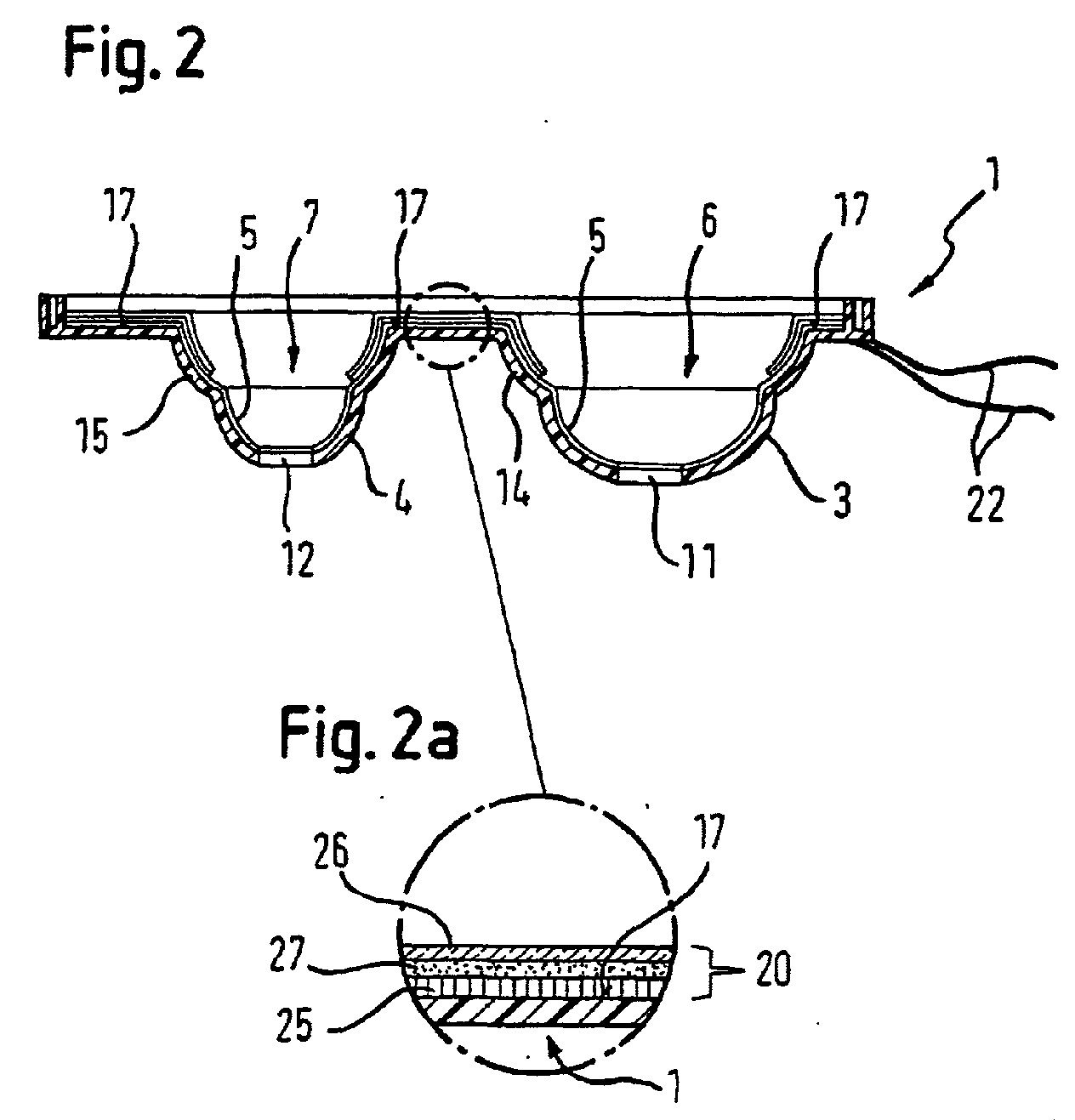
- FIGs 1, 2 and 2a is a plastic existing in a schematic manner Component 1 of a vehicle lamp shown, the two carriers 3, 4 of two reflectors 6, 7 associated with the two integrated into the vehicle lamp function lights are, for example, it is a front headlight and arranged next to it Direction indicator can act.
- a mirror layer 5 for example Of aluminum vapor-deposited, so that the light emitted to the rear and to the side of two light sources (not shown) inserted through the openings 11, 12 from behind deflected by the reflectors 6, 7 with a desired light distribution to the front and is emitted, which is achieved for example by the fact that the mirrored surfaces the carrier 3, 4 are designed as corresponding open spaces.
- the component 1 further comprises forward (i.e., upward in Figure 2). widening dome-shaped regions 14, 15, which continue the carrier 3, 4 to the front and transition into surface regions 17 which form the dome-shaped regions 14, 15 surround and connect in one piece.
- Both the surface areas 17 and the forward facing surfaces of dome-shaped regions 14, 15 are provided with an electroluminescent arrangement, which is formed in this embodiment by a single flat capacitor 20, the independent of the two function lights on the connecting line 22 so with a AC voltage is controlled that its between the base electrode 25 and the transparent cover electrode 26 located pigment layer 27 (see Figure 2a) lights up.
- the flat capacitor 20 could only arranged on a part of the visible from the outside surface areas 14, 15 and 17 be. It is only essential that he the light-emitting areas 23, 24 of the function lights not covered. Also, on the visible from the outside surface areas 14, 15 and 17, a plurality of flat capacitors may be provided which differ in color from each other differ and / or are independently controllable.
- the base electrode 25 of the one or more flat capacitors of the the same electrically conductive layer formed on the inside of the carrier 3, 4 is applied is to form the mirror layer 5 of the reflectors 6, 7.
- the whole forward, d. H. in Figure 2 upwardly facing side of the component 1 in its Produced with a continuous, electrically conductive, reflective layer 5, 25 steamed become.
- the flat capacitor 20 may be disposed between the pigment layer 27 and the base electrode 25 include an insulating layer (not shown) to increase its dielectric strength improve.
- the surface areas 17 of the component 1 are shown in Figures 1 and 2 as substantially flat surfaces shown. In fact, you can do any three-dimensional Own room form. They also have the light-emitting areas 23, 24 of the function lights not or not completely surrounded.
- the component 1 can be a in the installed state of the vehicle lamp below the function lights substantially perpendicular to the drawing plane of Figure 1 to the viewer to be extended part include or consist of such a part that does not have the "back wall” but the "bottom” of visible from the outside part of the vehicle lighting housing forms.
- a combined function of the component 1 both as a “back wall” as also as a “floor” is possible, with all its visible from the outside, the function lights non-occluding surfaces or even only a part thereof an electroluminescent lighting arrangement can carry.
- This electroluminescent lighting arrangement can, as already above for the base electrode described in layers vapor-deposited or by another spray or other Be applied coating method.
- this foil material can then be adapted in shape to the surface of the component 1 to be covered Multi-layer film element cut or punched out and by a thermoforming embossing process to the three-dimensional spatial form of the covered Surface of the component 1 are adapted so that it is placed in front of this and with this can be connected for example by gluing or clipping.
- this multilayer film element when the component 1 by injection molding is prepared to use in the relevant injection mold and then with the To inject component 1 forming material so as to connect it firmly with this.
- This one Light emission disk is made of a transparent material, how to particular 4a, the flat capacitor 20 in reverse order on their Rear side 30 applied, so that directly to this back 30, the transparent Cover electrode 26, to this the pigment layer 27 and to this, if desired, under Interposition of an insulating layer (not shown), the base electrode 25 connects, which can be designed as desired transparent or opaque.
- the electroluminescent lighting arrangement can again as a multilayer film element formed and in the manufacture of the light exit plate by Injected into the mold in question and then with the material of Rear diffuser be back-injected.
- the light exit window is not shown differently than in the figures but have a multi-dimensionally curved spatial form.
- the electroluminescent device is formed so that it at least the light passage areas 32, 34 leaves free for the two function lights.
Landscapes
- Engineering & Computer Science (AREA)
- Mechanical Engineering (AREA)
- Non-Portable Lighting Devices Or Systems Thereof (AREA)
- Electroluminescent Light Sources (AREA)
- Arrangements Of Lighting Devices For Vehicle Interiors, Mounting And Supporting Thereof, Circuits Therefore (AREA)
Abstract
Zur Erweiterung der gestalterischen und technischen Einsatzmöglichkeiten einer Fahrzeugleuchte,
insbesondere für Kraftfahrzeuge, die wenigstens einer Funktionsleuchte
und eine den Innenraum der Fahrzeugleuchte abdeckende Lichtaustrittsscheibe umfaßt,
ist auf Oberflächenbereichen wenigstens eines Bauteils (1) der Fahrzeugleuchte,
die von außen her sichtbar sind und die wenigstens eine Funktionsleuchte nicht verdecken,
eine Elektrolumineszenz-Anordnung vorgesehen, die wenigstens einen Flachkondensator
(20) umfaßt, der zumindest eine hintere Basiselektrode (25), eine im Betrieb
leuchtende Pigmentschicht (27) und eine transparente Deckelektrode (26) umfaßt.
Description
Die Erfindung betrifft eine Fahrzeugleuchte der im Oberbegriff von Anspruch 1 genannten Art.The invention relates to a vehicle lamp referred to in the preamble of claim 1 Art.
In letzter Zeit werden derartige Fahrzeugleuchten, bei denen es sich sowohl um Leuchten für die Vorder- als auch die Rückseite von Fahrzeugen, insbesondere Kraftfahrzeugen handeln kann, in zunehmendem Maße mit völlig transparenten, optisch inaktiven Lichtdurchtrittsscheiben gestaltet, die insbesondere keine die Raumverteilung des hindurchtretenden Lichts verändernden Strukturen besitzen und somit einen völlig freien Blick in das "Innere" der Fahrzeugleuchte ermöglichen. Dabei sind dann nicht nur der oder die meist von Reflektoren gebildeten Licht-Abstrahlbereiche der in die betreffende Fahrzeugleuchte integrierten Funktionsleuchten sondern auch die Oberflächen von weiteren Bauteilen sichtbar, welche diese Licht-Abstrahlbereiche umgeben bzw. sich von außen her gesehen neben diesen befinden. Bei diesen Bauteilen kann es sich um die Lichtaustrittsscheibe selbst handeln, deren Rückseite natürlich ebenfalls von außen her "sichtbar" ist, oder auch um Gehäuseteile wie z. B. die Rückwand und/oder die Bodenfläche des Leuchten-Gehäuses oder beliebige andere Bauteile.Recently, such vehicle lights, which are both lights act for the front and the back of vehicles, especially motor vehicles can, increasingly with completely transparent, optically inactive light transmission windows designed, in particular no the space distribution of the passing Possess light-changing structures and thus a completely clear view of the "inside" allow the vehicle lamp. It's not just the one or the other of reflectors formed light emission areas of integrated into the relevant vehicle lamp Functional lights but also the surfaces of other components visible, which Surround these light-emitting areas or seen from the outside next to these. These components may be the light exit plate itself, whose Back side, of course, also "visible" from the outside, or to housing parts such. B. the rear wall and / or the bottom surface of the lamp housing or any other Components.
Nach dem Stand der Technik werden diese sichtbaren Oberflächen, soweit es sich nicht um die Rückseite der Lichtaustrittsscheibe handelt, im allgemeinen entweder verspiegelt oder in der Farbe der Kraftfahrzeug-Karosserie lackiert.According to the prior art, these visible surfaces, as far as it is not the back of the light exit plate is, in general, either mirrored or in painted the color of the vehicle body.
Demgegenüber liegt der Erfindung die Aufgabe zugrunde, eine Fahrzeugleuchte der eingangs genannten Art so weiter zu bilden, daß sie sowohl in gestalterischer als auch funktionaler Hinsicht zusätzliche, beim Stand der Technik nicht vorhandene Möglichkeiten bietet.In contrast, the invention has the object, a vehicle lamp of the beginning so mentioned that they are both in design as well as functional Regard additional, not available in the prior art opportunities.
Zur Lösung dieser Aufgabe sieht die Erfindung die im Anspruch 1 niedergelegten Merkmale vor.To solve this problem, the invention provides the features set out in claim 1 in front.
Die eigentliche Funktionsleuchte bzw. Funktionsleuchten, die in die betreffende Fahrzeugleuchte integriert ist bzw. sind werden somit durch eine zusätzliche Elektrolumineszenz-Anordnung ergänzt, die wenigstens einen Elektrolumineszenz-Flachkondensator umfaßt und so angeordnet ist, daß sie von außen her neben dem Licht-Abstrahlbereich bzw. den Licht-Abstrahlbereichen der Funktionsleuchte bzw. Funktionsleuchten sichtbar ist, diese beispielsweise umgibt. Der wenigstens eine Elektrolumineszenz-Flachkondensator kann von der bzw. den Funktionsleuchten unabhängig oder gemeinsam mit diesen ansteuerbar sein. Dabei ist seine Leuchtintensität im allgemeinen deutlich geringer als die der Funktionsleuchten.The actual function lamp or function lights that are in the relevant vehicle lamp is integrated or are thus by an additional electroluminescent device supplemented, which comprises at least one electroluminescent flat capacitor and is arranged so that it from the outside next to the light-emitting area or the light-emitting areas the function lamp or function lights is visible, this example surrounds. The at least one electroluminescent flat capacitor can by the or the function lights independently or jointly with these be controlled. Its luminous intensity is generally much lower than that of the function lights.
Das Licht der Elektrolumineszenz-Leuchtanordnung dient mehreren Zwecken:
- es erweitert die Gestaltungsmöglichkeiten für die gesamte Fahrzeugleuchte und somit für das Design des Kraftfahrzeugs,.
- es verbessert die Erkennbarkeit der Dimensionen des Kraftfahrzeugs bei Nacht, da sich die Oberflächen, die mit der Elektrolumineszenz-Leuchtanordnung bedeckt sind, im allgemeinen weiter nach außen erstrecken können, als die eigentlichen Funktionsleuchten, und
- es erhöht die Sicherheit bei Ausfall einer Funktionsleuchte.
- it extends the design options for the entire vehicle lamp and thus for the design of the motor vehicle.
- it improves the visibility of the dimensions of the motor vehicle at night, since the surfaces which are covered with the electroluminescent lighting arrangement can generally extend further outward than the actual functional lights, and
- it increases safety in case of failure of a function light.
Im allgemeinen handelt es sich bei den oben erwähnten Licht-Abstrahlbereichen um die Licht-Austrittsöffnungen von Reflektoren, die parabolisch oder als Freiflächen-Reflektoren ausgebildet sein können und in welche die zugehörige Lichtquelle von hinten her eingesetzt ist.In general, the above-mentioned light emitting areas are those Light exit openings of reflectors, parabolic or as open space reflectors may be formed and in which the associated light source used from behind is.
Diese Reflektoren umfassen in bekannter Weise einen die Form ihrer Spiegelfläche vorgebenden, als Hohlkörper ausgebildeten Träger , der auf seiner inneren Oberfläche verspiegelt ist. Prinzipiell können der oder die Reflektoren der erfindungsgemäßen Fahrzeugleuchte aus Metall bestehen, doch ist es bevorzugt, daß sie aus Kunststoff hergestellt und auf ihrer Innenseite mit einer metallischen, spiegelnden Schicht, beispielsweise aus Aluminium bedampft sind. Die die Licht-Abstrahlbereiche dieser Reflektoren umgebenden Oberflächen können beispielsweise flächige Verbindungsstege umfassen, welche die Reflektoren einstückig miteinander verbinden und auf ihrer von außen her sichtbaren Oberfläche die erfindungsgemäße Elektrolumineszenz-Leuchtanordnung aufweisen. In diesem Fall kann dann das Bauteil der Leuchte, das die Elektrolumineszenz-Leuchtanordnung trägt, mit dem Reflektor-Träger oder den Reflektor-Trägern der Funktionsleuchte bzw. Funktionsleuchten einstückige ausgebildet werden.These reflectors comprise, in a known manner, a shape which predetermines the shape of their mirror surface, formed as a hollow body carrier, which is mirrored on its inner surface is. In principle, the one or more reflectors of the vehicle lamp according to the invention can Metal exist, but it is preferred that they are made of plastic and on its inside coated with a metallic, reflective layer, for example made of aluminum are. The surfaces surrounding the light-emitting areas of these reflectors For example, they may include laminar connection webs integrally forming the reflectors connect together and on their visible from the outside surface the inventive Have electroluminescent lighting arrangement. In that case, then the component of the lamp, which carries the electroluminescent light assembly, with the reflector-carrier or the reflector-carriers of the function lamp or functional lights integral be formed.
In gleicher Weise ist es aber auch möglich, die Elektrolumineszenz-Leuchtanordnung auf der Rückseite der transparenten Lichtaustrittsscheibe so anzuordnen, daß sie nur einen Licht-Durchtrittsbereich oder mehrere Licht-Durchtrittsbereiche für das Licht der Funktionsleuchte bzw. Funktionsleuchten frei läßt.In the same way, however, it is also possible for the electroluminescent lighting arrangement to arrange the back of the transparent light exit plate so that they only one Light passage area or multiple light passage areas for the light of the function lamp or function lights leaves free.
Eine Fahrzeugleuchte kann auch dann gemäß der Erfindung mit einer Elektrolumineszenz-Leuchtanordnung ausgestattet werden, wenn ihre Licht-Durchtrittsscheibe optisch aktive Strukturen trägt.A vehicle lamp can then according to the invention with an electroluminescent lighting arrangement be equipped if their light-passing disc optically active Structures carries.
Diese und weitere vorteilhafte Ausgestaltungen der erfindungsgemäßen Fahrzeugleuchte sowie bevorzugte Verfahren zu ihrer Herstellung sind in den Unteransprüchen niedergelegt. These and other advantageous embodiments of the vehicle lamp according to the invention as well as preferred processes for their preparation are laid down in the subclaims.
Die Erfindung wird im folgenden anhand von Ausführungsbeispielen unter Bezugnahme auf die Zeichnung beschrieben ; in dieser zeigen:
- Figur 1
- eine stark schematisierte Vorderansicht eines Bauteils für eine erfindungsgemäße Fahrzeugleuchte, das zwei einstückig miteinander verbundene Reflektoren für zwei in der betreffenden Fahrzeugleuchte zusammengefaßte Funktionsleuchten umfaßt,
- Figur 2
- einen Schnitt durch das Bauteil aus Figur 1 längs der Linie II-II,
- Figur 2a
- in vergrößertem Maßstab ein Detail aus Figur 2,
Figur 3- eine stark schematisierte Vorderansicht einer Lichtaustrittsscheibe für eine erfindungsgemäße Fahrzeugleuchte, die für zwei in der betreffenden Fahrzeugleuchte zusammengefaßte Funktionsleuchten zwei Licht-Durchtrittsbereiche aufweist,
- Figur 4
- einen Schnitt durch die Lichtaustrittsscheibe aus
Figur 3 längs der Linie IV-IV und - Figur 4a
- in vergrößertem Maßstab ein Detail aus Figur 4.
- FIG. 1
- a highly schematic front view of a component for a vehicle lamp according to the invention comprising two integrally connected reflectors for two summarized in the relevant vehicle lamp function lights,
- FIG. 2
- a section through the component of Figure 1 along the line II-II,
- FIG. 2a
- on an enlarged scale, a detail from FIG. 2,
- FIG. 3
- a highly schematic front view of a light exit window for a vehicle lamp according to the invention, which has two light passage areas for two combined in the relevant vehicle lamp function lights two
- FIG. 4
- a section through the light exit plate of Figure 3 along the line IV-IV and
- FIG. 4a
- on an enlarged scale, a detail of Figure 4.
In den Figuren 1, 2 und 2a ist in schematischer Weise ein aus Kunststoff bestehendes
Bauteil 1 einer Fahrzeugleuchte dargestellt, das die beiden Träger 3, 4 von zwei Reflektoren
6, 7 umfaßt, die zwei in die Fahrzeugleuchte integrierten Funktionsleuchten zugeordnet
sind, bei denen es sich beispielsweise um einen Front-Scheinwerfer und einen daneben angeordneten
Fahrtrichtungs-Anzeiger handeln kann.In Figures 1, 2 and 2a is a plastic existing in a schematic manner
Component 1 of a vehicle lamp shown, the two
Auf die Innenseite der beiden Träger 3, 4 ist jeweils eine Spiegelschicht 5, beispielsweise
aus Aluminium aufgedampft, so daß das nach hinten und zur Seite abgestrahlte Licht von
zwei von hinten her durch die Öffnungen 11, 12 eingesetzten Lichtquellen (nicht dargestellt)
durch die Reflektoren 6, 7 mit einer gewünschten Lichtverteilung nach vorne umgelenkt und
abgestrahlt wird, die beispielsweise dadurch erreicht wird, daß die verspiegelten Oberflächen
der Träger 3, 4 als entsprechende Freiflächen ausgebildet sind. Alternativ hierzu können
die Reflektoren 6, 7 aber auch in herkömmlicher Weise Parabolform besitzen.On the inside of the two
Wie man sieht, umfaßt das Bauteil 1 weiterhin sich nach vorne (d. h. in Figur 2 nach oben)
erweiternde kalottenförmige Bereiche 14, 15, welche die Träger 3, 4 nach vorne fortsetzen
und in Oberflächenbereiche 17 übergehen, welche die kalottenförmigen Bereiche 14, 15
umgeben und einstückig miteinander verbinden.As can be seen, the component 1 further comprises forward (i.e., upward in Figure 2).
widening dome-
Sowohl die Oberflächenbereiche 17 als auch die nach vorne weisenden Oberflächen der
kalottenförmigen Bereiche 14, 15 sind mit einer Elektrolumineszenz-Anordnung versehen,
die bei diesem Ausführungsbeispiel von einem einzigen Flachkondensator 20 gebildet wird,
der unabhängig von den beiden Funktionsleuchten über die Anschlußleitung 22 so mit einer
Wechselspannung ansteuerbar ist, daß seine zwischen der Basiselektrode 25 und der
transparenten Deckelektrode 26 befindliche Pigmentschicht 27 (siehe Figur 2a) leuchtet.Both the
Alternativ zu der dargestellten Ausführungsform könnte der Flachkondensator 20 auch nur
auf einem Teil der von außen her sichtbaren Flächenbereiche 14, 15 und 17 angeordnet
sein. Wesentlich ist lediglich, daß er die Licht-Abstrahlbereiche 23, 24 der Funktionsleuchten
nicht verdeckt. Auch können auf den von außen her sichtbaren Flächenbereichen 14, 15
und 17 mehrere Flachkondensatoren vorgesehen sein, die sich hinsichtlich ihrer Farbe voneinander
unterscheiden und/oder voneinander unabhängig ansteuerbar sind.Alternatively to the illustrated embodiment, the
Vorteilhafterweise wird die Basiselektrode 25 des oder der Flachkondensatoren von der
gleichen elektrisch leitenden Schicht gebildet, die auf die Innenseite der Träger 3, 4 aufgebracht
ist, um die Spiegelschicht 5 der Reflektoren 6, 7 zu bilden. In diesem Falle kann die
gesamte nach vorne, d. h. in Figur 2 nach oben weisende Seite des Bauteils 1 bei dessen
Herstellung mit einer durchgehenden, elektrisch leitfähigen, spiegelnden Schicht 5, 25 bedampft
werden.Advantageously, the
Der Flachkondensator 20 kann zwischen der Pigmentschicht 27 und der Basiselektrode 25
eine (nicht dargestellte) Isolationsschicht umfassen, um seine Durchschlagsfestigkeit zu
verbessern.The
Die Oberflächenbereiche 17 des Bauteils 1 sind in den Figuren 1 und 2 als im wesentlichen
ebene Flächen dargestellt. Tatsächlich können Sie aber jede beliebige, dreidimensionale
Raumform besitzen. Auch müssen sie die Licht-Abstrahlbereiche 23, 24 der Funktionsleuchten
nicht oder nicht vollständig umgeben. Beispielsweise kann das Bauteil 1 einen sich
im eingebauten Zustand der Fahrzeugleuchte unterhalb der Funktionsleuchten im wesentlichen
senkrecht zur Zeichenebene der Figur 1 auf den Betrachter zu erstreckenden Teil
umfassen beziehungsweise aus einem solchen Teil bestehen, der dann nicht die "Rückwand"
sondern den "Boden" des von außen her sichtbaren Teils des Fahrzeugleuchten-Gehäuses
bildet. Auch eine kombinierte Funktion des Bauteils 1 sowohl als "Rückwand" als
auch als "Boden" ist möglich, wobei alle seine von außen her sichtbaren, die Funktionsleuchten
nicht verdeckenden Oberflächen oder aber auch nur einen Teil hiervon eine Elektrolumineszenz-Leuchtanordnung
tragen können.The
Diese Elektrolumineszenz-Leuchtanordnung kann, wie oben bereits für die Basiselektrode beschrieben, schichtenweise aufgedampft oder durch ein anderes Sprüh- oder sonstiges Beschichtungsverfahren aufgebracht sein. Alternativ hierzu ist es möglich, die Elektrolumineszenz-Leuchtanordnung vom Bauteil 1 zunächst getrennt als ebenes "endloses" Folienmaterial herzustellen, daß auf einer tiefziehbaren metallischen Trägerfolie, die gleichzeitig als Basiselektrode dienen kann, die übrigen zur Bildung eines Elektrolumineszenz-Flachkondensators erforderlichen, oben geschilderten Schichten beträgt. Aus diesem Folienmaterial kann dann einen in seiner Form an die abzudeckende Oberfläche des Bauteils 1 angepaßtes Mehrschichten-Folienelement ausgeschnitten beziehungsweise ausgestanzt und durch einen Tiefzieh-Prägevorgang an die dreidimensionale Raumform der abzudeckenden Oberfläche des Bauteils 1 so angepaßt werden, daß es vor diese gesetzt und mit dieser beispielsweise durch Kleben oder Aufclipsen verbunden werden kann. Besonders bevorzugt ist es jedoch, dieses Mehrschichten-Folienelement dann, wenn das Bauteil 1 durch Spritzguß hergestellt wird, in die betreffende Spritzguß-Form einzusetzen und dann mit dem das Bauteil 1 bildenden Material zu hinterspritzen, um es so mit diesem fest zu verbinden.This electroluminescent lighting arrangement can, as already above for the base electrode described in layers vapor-deposited or by another spray or other Be applied coating method. Alternatively, it is possible to use the electroluminescent lighting arrangement separated from the component 1 initially as a flat "endless" film material make that on a thermoformable metallic carrier film, simultaneously can serve as a base electrode, the rest to form a electroluminescent flat capacitor required, above-described layers amounts. For this foil material can then be adapted in shape to the surface of the component 1 to be covered Multi-layer film element cut or punched out and by a thermoforming embossing process to the three-dimensional spatial form of the covered Surface of the component 1 are adapted so that it is placed in front of this and with this can be connected for example by gluing or clipping. Especially preferred However, it is, this multilayer film element when the component 1 by injection molding is prepared to use in the relevant injection mold and then with the To inject component 1 forming material so as to connect it firmly with this.
Bei dem in den Figuren 3, 4 und 4a wiedergegebenen Ausführungsbeispiel sind Teile, die in entsprechender Weise auch in den Figuren 1, 2 und 2a vorhanden sind, mit den gleichen Bezugszeichen bezeichnet.In the embodiment shown in FIGS. 3, 4 and 4a, parts which are shown in FIG corresponding manner also in Figures 1, 2 and 2a are present, with the same Reference numeral.
Der wesentliche Unterschied zu dem zuvor beschriebenen Ausführungsbeispiel besteht
darin, daß nunmehr das Bauteil 1, welches auf einer seiner Oberflächen die Elektrolumineszenz-Anordnung
mit dem wenigstens einen Flachkondensator 20 trägt, die
Lichtaustrittsscheibe der erfindungsgemäßen Fahrzeugleuchte ist. Da diese
Lichtaustrittsscheibe aus einem transparenten Material besteht, ist, wie man insbesondere
der Figur 4a entnimmt, der Flachkondensator 20 in umgekehrter Reihenfolge auf ihre
Rückseite 30 aufgebracht, sodaß sich unmittelbar an diese Rückseite 30 die transparenten
Deckelektrode 26, an diese die Pigmentschicht 27 und an diese, gewünschtenfalls unter
Zwischenschaltung einer (nicht dargestellten) Isolationsschicht, die Basiselektrode 25
anschließt, die je nach Wunsch transparent oder lichtundurchlässig ausgebildet sein kann.The essential difference from the previously described embodiment
in that now the component 1, which on one of its surfaces, the electroluminescent device
with the at least one
Alle oben gemachten Aussagen hinsichtlich der Art der Aufbringung der Elektrolumineszenz-Anordnung auf das Bauteil 1 und ihrer Ausgestaltung gelten hier in entsprechender Weise. Insbesondere kann die Elektrolumineszenz-Leuchtanordnung wieder als Mehrschichten-Folienelement ausgebildet und bei der Herstellung der Lichtaustrittsscheibe durch Spritzguß in die betreffende Form eingelegt und dann mit dem Material der Lichtaustrittsscheibe hinterspritzt werden.All statements made above concerning the manner of application of the electroluminescent device to the component 1 and its configuration apply here in the corresponding Wise. In particular, the electroluminescent lighting arrangement can again as a multilayer film element formed and in the manufacture of the light exit plate by Injected into the mold in question and then with the material of Rear diffuser be back-injected.
Im Regelfall wird die Lichtaustrittsscheibe anders als in den Figuren dargestellt, nicht eben sein sondern eine mehrdimensional gekrümmte Raumform besitzen.As a rule, the light exit window is not shown differently than in the figures but have a multi-dimensionally curved spatial form.
Es versteht sich, das die Elektrolumineszenz-Anordnung so geformt wird, daß sie zumindest
die Licht-Durchtrittsbereiche 32, 34 für die beiden Funktionsleuchten frei läßt.It is understood that the electroluminescent device is formed so that it at least
the
Claims (12)
Applications Claiming Priority (2)
| Application Number | Priority Date | Filing Date | Title |
|---|---|---|---|
| DE10341572A DE10341572B4 (en) | 2003-09-09 | 2003-09-09 | Vehicle lamp with electroluminescent arrangement |
| DE10341572 | 2003-09-09 |
Publications (2)
| Publication Number | Publication Date |
|---|---|
| EP1514731A2 true EP1514731A2 (en) | 2005-03-16 |
| EP1514731A3 EP1514731A3 (en) | 2007-01-03 |
Family
ID=34129721
Family Applications (1)
| Application Number | Title | Priority Date | Filing Date |
|---|---|---|---|
| EP04020672A Withdrawn EP1514731A3 (en) | 2003-09-09 | 2004-08-31 | Vehicle lamp |
Country Status (3)
| Country | Link |
|---|---|
| US (1) | US7168838B2 (en) |
| EP (1) | EP1514731A3 (en) |
| DE (1) | DE10341572B4 (en) |
Cited By (1)
| Publication number | Priority date | Publication date | Assignee | Title |
|---|---|---|---|---|
| WO2007112715A1 (en) * | 2006-03-31 | 2007-10-11 | Eads Deutschland Gmbh | Self-luminous element, and method for the production thereof |
Families Citing this family (10)
| Publication number | Priority date | Publication date | Assignee | Title |
|---|---|---|---|---|
| WO2004104474A1 (en) * | 2003-05-23 | 2004-12-02 | Volkswagen Aktiengesellschaft | Headlight or light for a motor vehicle |
| DE102006001976B4 (en) * | 2006-01-13 | 2008-02-28 | Detlef Mester | Luminaire comprising a pane |
| DE102007021179B4 (en) * | 2007-05-05 | 2016-10-13 | Dr. Ing. H.C. F. Porsche Aktiengesellschaft | Motor vehicle light |
| DE102007021865B4 (en) * | 2007-05-10 | 2012-10-31 | Automotive Lighting Reutlingen Gmbh | Lighting device for a vehicle |
| JP2011150888A (en) * | 2010-01-21 | 2011-08-04 | Koito Mfg Co Ltd | Vehicular lighting fixture using planar light-emitting body for sub light source |
| US20130171903A1 (en) | 2012-01-03 | 2013-07-04 | Andrew Zsinko | Electroluminescent devices and their manufacture |
| US9642212B1 (en) | 2015-06-11 | 2017-05-02 | Darkside Scientific, Llc | Electroluminescent system and process |
| DE102015110242A1 (en) * | 2015-06-25 | 2016-12-29 | Osram Oled Gmbh | lamp |
| CA3031612A1 (en) | 2016-07-28 | 2018-02-01 | Darkside Scientific, Inc. | Electroluminescent system and process |
| DE102018133306A1 (en) | 2018-12-21 | 2020-06-25 | Bayerische Motoren Werke Aktiengesellschaft | Motor vehicle component with light function |
Family Cites Families (12)
| Publication number | Priority date | Publication date | Assignee | Title |
|---|---|---|---|---|
| US6392341B2 (en) * | 1993-07-20 | 2002-05-21 | University Of Georgia Research Foundation, Inc. | Resonant microcavity display with a light distribution element |
| US5709453A (en) * | 1994-08-16 | 1998-01-20 | Krent; Edward D. | Vehicle lighting having remote light source |
| US5620348A (en) * | 1995-05-12 | 1997-04-15 | Timex Corporation | Method of manufacturing electroluminescent lamps having surface designs and lamps produced thereby |
| JPH10143098A (en) * | 1996-11-08 | 1998-05-29 | Minnesota Mining & Mfg Co <3M> | Retroreflecting sheet capabile of emitting light by itself, and reflective indicator |
| AT405633B (en) * | 1997-10-13 | 1999-10-25 | Magna Auteca Zweigniederlassun | Light |
| DE19745993C2 (en) * | 1997-10-20 | 1999-11-11 | Daimler Chrysler Ag | Vehicle with electroluminescent light strip |
| DE29915295U1 (en) * | 1999-09-01 | 2001-01-11 | Gutgar, Ullrich, 42719 Solingen | Device for improving the passive safety of motor vehicles in the dark |
| DE19963336A1 (en) * | 1999-12-27 | 2001-07-12 | Hella Kg Hueck & Co | Lighting device and method for illuminating a coupling-out space for vehicles |
| DE10115806A1 (en) * | 2001-03-30 | 2002-10-10 | Bayerische Motoren Werke Ag | Exterior lighting device for the exterior lighting of a vehicle |
| DE20117292U1 (en) * | 2001-10-22 | 2002-01-17 | Reitter & Schefenacker GmbH & Co. KG, 73730 Esslingen | Interior light for vehicles, preferably for motor vehicles |
| US7030774B2 (en) * | 2001-12-07 | 2006-04-18 | General Motors Corporation | Floating visible indicator for an instrument cluster |
| US6926972B2 (en) * | 2002-01-10 | 2005-08-09 | Basf Corporation | Method of providing an electroluminescent coating system for a vehicle and an electroluminescent coating system thereof |
-
2003
- 2003-09-09 DE DE10341572A patent/DE10341572B4/en not_active Expired - Fee Related
-
2004
- 2004-08-31 EP EP04020672A patent/EP1514731A3/en not_active Withdrawn
- 2004-09-02 US US10/932,336 patent/US7168838B2/en not_active Expired - Fee Related
Cited By (1)
| Publication number | Priority date | Publication date | Assignee | Title |
|---|---|---|---|---|
| WO2007112715A1 (en) * | 2006-03-31 | 2007-10-11 | Eads Deutschland Gmbh | Self-luminous element, and method for the production thereof |
Also Published As
| Publication number | Publication date |
|---|---|
| US20050083710A1 (en) | 2005-04-21 |
| EP1514731A3 (en) | 2007-01-03 |
| DE10341572B4 (en) | 2005-08-11 |
| US7168838B2 (en) | 2007-01-30 |
| DE10341572A1 (en) | 2005-05-04 |
Similar Documents
| Publication | Publication Date | Title |
|---|---|---|
| DE102007005551A1 (en) | Luminaire for vehicles, preferably for motor vehicles | |
| DE19822636A1 (en) | Lighting device on motor vehicle door | |
| DE102012003200A1 (en) | Translucent panel of outer structure of motor vehicle, has external coating made of transparent or translucent material is coated on outer surface of light-emitting element, so that light-emitting element is translucent to light | |
| DE20207799U1 (en) | Signal light for vehicles | |
| DE20114561U1 (en) | edge luminaire | |
| DE19859195A1 (en) | Sight integrated component part of compound material with at least one carrier layer and at least partly light permeable decorative layer also light reflecting surface for background illumination of decorative layer | |
| DE102018214790A1 (en) | Lighting device for a motor vehicle | |
| EP3421278B1 (en) | Illuminated decorative strip | |
| DE10341572B4 (en) | Vehicle lamp with electroluminescent arrangement | |
| EP4371103A1 (en) | Method for producing an illuminated device for a vehicle | |
| DE102012211821B4 (en) | Luminaire unit for a motor vehicle, in which lamps are arranged in a housing shell with window portion | |
| EP1737701A1 (en) | Exterior rearview mirror for vehicles, especially for motor vehicles | |
| EP3631290A1 (en) | Lighting device for lighting the interior of a motor vehicle | |
| DE10320614B4 (en) | Cover for an opening in a vehicle roof and manufacturing method therefor | |
| EP3792111B1 (en) | Lamp | |
| EP1775512A1 (en) | Lighting device for vehicles, preferably rear lamp for automotive vehicles | |
| EP2152544A1 (en) | Illumination device for illuminating the inside of a vehicle | |
| DE202010012968U1 (en) | On a furniture part attached light bar | |
| EP3353582B1 (en) | Optical film and light fixture with such an optical film | |
| EP3814172B1 (en) | Method for producing a blinker module, blinker module, rear-view device, and motor vehicle | |
| DE102008045447A1 (en) | Panel, particularly front panel, panoramic windscreen or glass roof for motor vehicle, has transparent layer and illuminant, where transparent conductor structure is provided for energy supply of illuminant | |
| DE102006021973A1 (en) | Luminaire with at least one lighting unit for vehicles, preferably for motor vehicles | |
| DE202013105487U1 (en) | Motor vehicle light | |
| DE102020204906A1 (en) | Tailgate of a vehicle with a lighting arrangement on a one-piece outer panel | |
| DE102020201645A1 (en) | Lighting device for a motor vehicle |
Legal Events
| Date | Code | Title | Description |
|---|---|---|---|
| PUAI | Public reference made under article 153(3) epc to a published international application that has entered the european phase |
Free format text: ORIGINAL CODE: 0009012 |
|
| AK | Designated contracting states |
Kind code of ref document: A2 Designated state(s): AT BE BG CH CY CZ DE DK EE ES FI FR GB GR HU IE IT LI LU MC NL PL PT RO SE SI SK TR |
|
| AX | Request for extension of the european patent |
Extension state: AL HR LT LV MK |
|
| PUAL | Search report despatched |
Free format text: ORIGINAL CODE: 0009013 |
|
| AK | Designated contracting states |
Kind code of ref document: A3 Designated state(s): AT BE BG CH CY CZ DE DK EE ES FI FR GB GR HU IE IT LI LU MC NL PL PT RO SE SI SK TR |
|
| AX | Request for extension of the european patent |
Extension state: AL HR LT LV MK |
|
| RIC1 | Information provided on ipc code assigned before grant |
Ipc: B60Q 3/00 20060101ALN20061130BHEP Ipc: F21K 2/00 20060101ALN20061130BHEP Ipc: G09F 13/22 20060101ALN20061130BHEP Ipc: H05B 33/00 20060101ALI20061130BHEP Ipc: F21S 8/10 20060101ALI20061130BHEP Ipc: B60Q 1/26 20060101AFI20041230BHEP |
|
| STAA | Information on the status of an ep patent application or granted ep patent |
Free format text: STATUS: THE APPLICATION IS DEEMED TO BE WITHDRAWN |
|
| 18D | Application deemed to be withdrawn |
Effective date: 20070301 |