EP1514640B1 - Method and apparatus for finishing shafts, especially crank- and camshafts - Google Patents
Method and apparatus for finishing shafts, especially crank- and camshafts Download PDFInfo
- Publication number
- EP1514640B1 EP1514640B1 EP20040020483 EP04020483A EP1514640B1 EP 1514640 B1 EP1514640 B1 EP 1514640B1 EP 20040020483 EP20040020483 EP 20040020483 EP 04020483 A EP04020483 A EP 04020483A EP 1514640 B1 EP1514640 B1 EP 1514640B1
- Authority
- EP
- European Patent Office
- Prior art keywords
- belt
- workpiece
- abrasive belt
- abrasive
- support
- Prior art date
- Legal status (The legal status is an assumption and is not a legal conclusion. Google has not performed a legal analysis and makes no representation as to the accuracy of the status listed.)
- Expired - Fee Related
Links
Images
Classifications
-
- B—PERFORMING OPERATIONS; TRANSPORTING
- B24—GRINDING; POLISHING
- B24B—MACHINES, DEVICES, OR PROCESSES FOR GRINDING OR POLISHING; DRESSING OR CONDITIONING OF ABRADING SURFACES; FEEDING OF GRINDING, POLISHING, OR LAPPING AGENTS
- B24B19/00—Single-purpose machines or devices for particular grinding operations not covered by any other main group
- B24B19/08—Single-purpose machines or devices for particular grinding operations not covered by any other main group for grinding non-circular cross-sections, e.g. shafts of elliptical or polygonal cross-section
- B24B19/12—Single-purpose machines or devices for particular grinding operations not covered by any other main group for grinding non-circular cross-sections, e.g. shafts of elliptical or polygonal cross-section for grinding cams or camshafts
-
- B—PERFORMING OPERATIONS; TRANSPORTING
- B24—GRINDING; POLISHING
- B24B—MACHINES, DEVICES, OR PROCESSES FOR GRINDING OR POLISHING; DRESSING OR CONDITIONING OF ABRADING SURFACES; FEEDING OF GRINDING, POLISHING, OR LAPPING AGENTS
- B24B21/00—Machines or devices using grinding or polishing belts; Accessories therefor
- B24B21/02—Machines or devices using grinding or polishing belts; Accessories therefor for grinding rotationally symmetrical surfaces
-
- B—PERFORMING OPERATIONS; TRANSPORTING
- B24—GRINDING; POLISHING
- B24B—MACHINES, DEVICES, OR PROCESSES FOR GRINDING OR POLISHING; DRESSING OR CONDITIONING OF ABRADING SURFACES; FEEDING OF GRINDING, POLISHING, OR LAPPING AGENTS
- B24B21/00—Machines or devices using grinding or polishing belts; Accessories therefor
- B24B21/18—Accessories
- B24B21/20—Accessories for controlling or adjusting the tracking or the tension of the grinding belt
-
- B—PERFORMING OPERATIONS; TRANSPORTING
- B24—GRINDING; POLISHING
- B24B—MACHINES, DEVICES, OR PROCESSES FOR GRINDING OR POLISHING; DRESSING OR CONDITIONING OF ABRADING SURFACES; FEEDING OF GRINDING, POLISHING, OR LAPPING AGENTS
- B24B5/00—Machines or devices designed for grinding surfaces of revolution on work, including those which also grind adjacent plane surfaces; Accessories therefor
- B24B5/36—Single-purpose machines or devices
- B24B5/42—Single-purpose machines or devices for grinding crankshafts or crankpins
Landscapes
- Engineering & Computer Science (AREA)
- Mechanical Engineering (AREA)
- Finish Polishing, Edge Sharpening, And Grinding By Specific Grinding Devices (AREA)
- Grinding And Polishing Of Tertiary Curved Surfaces And Surfaces With Complex Shapes (AREA)
Description
Die Erfindung betrifft ein Verfahren zur Finishbearbeitung von Wellen, insbes. von Kurbel- und Nockenwellen, wobei eine Werkstückfläche eines um seine Rotationsachse rotierenden Werkstückes mit Hilfe eines kontinuierlich angetriebenen endlosen Schleifbandes bearbeitet wird und wobei das Schleifband mit einer Spannvorrichtung gespannt und an seiner Rückseite im Bereich der Werkstückfläche von einem endlosen, in diesem Bereich parallel zum Schleifband gespannten Stützband gestützt wird, und eine Vorrichtung gemäß dem Oberbegriff des Anspruchs 5.The invention relates to a method for finish machining of shafts, esp. Of crankshaft and camshaft, wherein a workpiece surface of a rotating about its axis workpiece is processed by means of a continuously driven endless abrasive belt and wherein the abrasive belt tensioned with a tensioning device and on its rear side in the area the workpiece surface is supported by an endless, in this area parallel to the grinding belt tensioned support belt, and a device according to the preamble of
Ein Verfahren und eine Vorrichtung mit den eingangs beschriebenen Merkmalen ist aus der Druckschrift
Der Erfindung liegt die Aufgabe zugrunde, ein Verfahren zur Finishbearbeitung von Wellen, insbes. von Kurbel- und Nockenwellen anzugeben, das eine gleichmäßige und auf die zu bearbeitende Werkstückfläche gezielt abstimmbare Finishbearbeitung ermöglicht.The invention has for its object to provide a method for finish machining of waves, esp. Of crankshafts and camshafts, which allows a uniform and targeted to the workpiece surface to be machined finishing machining.
Die Aufgabe wird erfindungsgemäß durch ein Verfahren nach Anspruch 1 und durch eine Vorrichtung nach Anspruch 5 gelöst. Das Schleifband und das Stützband umschlingen das Werkstück teilweise, so dass das Schleifband am Umfang des Werkstückes flächig anliegt. Das Stützband wird mittels einer separaten zweiten Spannvorrichtung gespannt. Bei dem erfindungsgemäßen Verfahren liegt das Schleifband flächig mit gleichmäßiger Flächenpressung an der zu bearbeitenden Werkstückfläche an, wobei die Anpresskraft des Schleifbandes durch die separate Spannvorrichtung des Stützbandes gezielt einstellbar ist. Ferner erlaubt der Schleifbandantrieb eine gezielte Abstimmung der Schnittgeschwindigkeit auf die zu bearbeitende Oberfläche. Insbes. sind auch bei kleinen Werkstückdurchmessern hohe Schnittgeschwindigkeiten, welche für die Gewährleistung von guten Finishergebnissen erforderlich sind, einstellbar. Im Ergebnis ermöglicht das erfindungsgemäße Verfahren eine Finishbearbeitung von Werkstückflächen, die hohen Anforderungen an die Oberflächengüte entsprechen.The object is achieved by a method according to claim 1 and by a device according to
Das Stützband besteht aus Metall und folglich aus einem zugfesten Material mit hohem Elastizitätsmodul.The support band is made of metal and consequently of a high tensile modulus material.
Das Stützband kann maschinenfest gespannt werden. Gemäß einer bevorzugten Ausführung der Erfindung wird das Stützband ebenfalls kontinuierlich und mit gleicher Bewegungsrichtung wie das Schleifband abgetrieben. Hierdurch kann die mechanische Beanspruchung des Schleifbandes reduziert werden, so dass auch Schleifbänder mit geringer Zugfestigkeit eingesetzt werden können. Vorzugsweise entspricht die Geschwindigkeit des Stützbandes der Geschwindigkeit des Schleifbandes.The support belt can be tensioned machine-resistant. According to a preferred embodiment of the invention, the support belt is also driven continuously and with the same direction of movement as the abrasive belt. As a result, the mechanical stress of the abrasive belt can be reduced, so that even sanding belts with low tensile strength can be used. Preferably, the speed of the support belt corresponds to the speed of the sanding belt.
Das Schleifband liegt mit einem Umschlingungswinkel von mehr als 90° flächig an der zu bearbeitenden Umfangsfläche des Werkstückes an. Dies erlaubt eine sehr gleichmäßige Bearbeitung des Werkstückes.The sanding belt lies with a wrap angle of more than 90 ° flat against the peripheral surface of the workpiece to be machined. This allows a very uniform machining of the workpiece.
Gegenstand der Erfindung ist auch eine Vorrichtung nach Anspruch 5 zur Durchführung des Verfahrens. Bevorzugte Ausführungen dieser Vorrichtung sind in den Ansprüchen 6 bis 8 beschrieben.The invention also provides a device according to
Im Folgenden wird die Erfindung anhand einer lediglich ein Ausführungsbeispiel darstellenden Zeichnung ausführlich erläutert. Es zeigen schematisch:
- Fig. 1
- eine Seitenansicht einer erfindungsgemäßen Vorrichtung zur Finisbearbeitung von Wellen,
- Fig. 2 und 3
- weitere Ausgestaltungen der erfindungsgemäßen Vorrichtung ebenfalls in einer Seitenansicht.
- Fig. 1
- a side view of a device according to the invention for Finisbearbeitung of waves,
- FIGS. 2 and 3
- Further embodiments of the device according to the invention also in a side view.
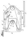
Die
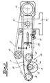
Die Fig. 2 zeigt eine weitere Ausgestaltung der erfindungsgemäßen Vorrichtung. Der Werkzeugträger 1 folgt hier der Umlaufbewegung des um seine Rotationsachse A rotierenden Werkstückes 3, welches in der Fig. 2 als Kurbelwelle ausgebildet ist. Es sind zwei parallel zum Werkstück 3 angeordnete Lagerwellen 12, 12' vorgesehen, deren Gestalt dem Werkstück 3 entspricht. Die Lagerwellen 12, 12' rotieren synchron und phasengleich zum Werkstück 3 um ihre Achsen B, B'. Der Werkzeugträger 1 ist an Umfangsflächen 13, 13' der Lagerwellen 12, 12' gelagert, die der zu bearbeitenden Fläche des Werkstückes 3 entsprechen. In Fig. 2 ist ein separater Stützbandantrieb 14 vorgesehen, welcher das Stützband 8 kontinuierlich antreibt. Die gleichgerichteten Bandgeschwindigkeiten von Schleifband 2 und Stützband 8 sind auch in diesem Ausführungsbeispiel identisch.Fig. 2 shows a further embodiment of the device according to the invention. The tool holder 1 follows here the orbital movement of the rotating about its axis of
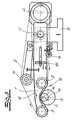
Bei der in der
Claims (8)
- A method for the finish-processing of shafts, more preferably crankshafts and camshafts, wherein a workpiece surface of a workpiece (3) rotating about its axis of rotation (A) is processed with the help of a continuously driven continuous abrasive belt (2) wherein the abrasive belt (2) is tensioned with a tensioning device (5) and at its back in the region of the workpiece surface is supported by a continuous support belt (8) tensioned in this region parallel to the abrasive belt, characterised in that the abrasive belt (2) and the support belt (8) partially wrap the workpiece (3) so that the abrasive belt (2) in a flat manner hugs the circumferential surface of the workpiece (3) to be processed with a wrapping angle (α) of more than 90°, in that a support belt (8) of metal is used and in that the support belt (8) is tensioned by means of a separate second tensioning device (5).
- The method according to Claim 1, characterised in that the support belt (8) during the processing of the workpiece surface is stationary.
- The method according to Claim 1, characterised in that the support belt (8) is likewise driven continuously and with the same movement direction as the abrasive belt (2).
- The method according to Claim 3, characterised in that the speed of the support belt (8) corresponds to the speed of the abrasive belt (2).
- A device with
tool carrier (1),
continuous abrasive belt (2) for the finish-processing of a workpiece (3) rotatingly driven about its axis of rotation (A),
an abrasive belt drive (4), which continuously drives the abrasive belt (2) during workpiece processing and
a tensioning device (5) for the abrasive belt (2),
wherein the tool carrier (1) comprises a processing head (6) with two belt deflections (7) spaced from each other, which limit a working region (L) of the processing head (6), wherein the abrasive belt (2) is guided via the belt deflections (7) of the processing head (6) and wherein a continuous support belt (8) is provided, which is tensioned in the working region (L) of the processing head (6) parallel to the abrasive belt (2) and in the working region (L) supports the back of the abrasive belt (2), characterised in that for carrying out the method according to any one of the Claims 1 to 4 the processing head (6) engages about the circumferential surface of the workpiece (3) fork-like so that the abrasive belt (2) loaded at the back by the support belt (8) partially wraps the workpiece (3) and in a flat manner hugs the circumferential surface of the workpiece (3) to be processed with a wrapping angle (α) of more than 90°, and that the support belt (8) consists of metal and is tensioned with the help of a second tensioning device (9). - The device according to Claim 5, characterised in that the support belt (8) together with the abrasive belt (2) is guided via the belt deflections (6) limiting the working region (L) and is driven by the abrasive belt drive (4) or a separate support belt drive (14).
- The device according to Claim 5 or 6, characterised in that the tensioning devices (5, 9) and the drives (4, 14) for the abrasive belt (2) and the support belt (8) are arranged on the tool carrier (1).
- The device according to any one of the Claims 5 to 7, characterised in that the tensioning devices (5, 9) comprise adjusting devices (10) for changing the belt lengths in the working region (L).
Applications Claiming Priority (2)
| Application Number | Priority Date | Filing Date | Title |
|---|---|---|---|
| DE10342134 | 2003-09-12 | ||
| DE2003142134 DE10342134B4 (en) | 2003-09-12 | 2003-09-12 | Method and device for finishing crankshafts and camshafts |
Publications (3)
| Publication Number | Publication Date |
|---|---|
| EP1514640A2 EP1514640A2 (en) | 2005-03-16 |
| EP1514640A3 EP1514640A3 (en) | 2006-03-01 |
| EP1514640B1 true EP1514640B1 (en) | 2010-05-26 |
Family
ID=34129774
Family Applications (1)
| Application Number | Title | Priority Date | Filing Date |
|---|---|---|---|
| EP20040020483 Expired - Fee Related EP1514640B1 (en) | 2003-09-12 | 2004-08-28 | Method and apparatus for finishing shafts, especially crank- and camshafts |
Country Status (2)
| Country | Link |
|---|---|
| EP (1) | EP1514640B1 (en) |
| DE (2) | DE10342134B4 (en) |
Cited By (3)
| Publication number | Priority date | Publication date | Assignee | Title |
|---|---|---|---|---|
| WO2012065949A1 (en) | 2010-11-17 | 2012-05-24 | Nagel Maschinen- Und Werkzeugfabrik Gmbh | Method and device for finish machining curved workpiece surfaces on workpieces by means of a finish belt |
| DE102011081918A1 (en) | 2011-08-31 | 2013-02-28 | Nagel Maschinen- Und Werkzeugfabrik Gmbh | Finishing machine for finishing curved workpiece surfaces on workpieces |
| TWI725225B (en) * | 2017-08-30 | 2021-04-21 | 日商荏原製作所股份有限公司 | Grinding device and grinding method |
Families Citing this family (13)
| Publication number | Priority date | Publication date | Assignee | Title |
|---|---|---|---|---|
| SG134176A1 (en) * | 2006-01-09 | 2007-08-29 | Giken Sakata S Ltd | An apparatus for grinding a work piece |
| DE102007051047B4 (en) * | 2007-10-16 | 2023-03-23 | Nagel Maschinen- Und Werkzeugfabrik Gmbh | Press-on device for finishing belt and device and method for finishing peripheral surfaces on cylindrical workpiece sections |
| EP2617522B1 (en) * | 2012-01-23 | 2014-01-15 | Supfina Grieshaber GmbH & Co. KG | Device for finely processing a peripheral area of the workpiece fixed in an eccentric manner to a peripheral area of a workpiece |
| CN104139333B (en) * | 2014-07-11 | 2016-05-18 | 山东金宝电子股份有限公司 | The method for grinding of copper foil surface processor rubber roll glue-line and the arc board clamp of use thereof |
| DE102015005915A1 (en) * | 2015-05-07 | 2016-11-10 | Jakob Löwer Inh. von Schumann GmbH & Co. KG | Deburring machine for deburring metal workpieces |
| DE102015221939B4 (en) * | 2015-11-09 | 2018-10-31 | Supfina Grieshaber Gmbh & Co. Kg | Finishing belt device and method for finish machining a workpiece |
| CN106425768B (en) * | 2016-09-23 | 2018-06-01 | 杭州新松机器人自动化有限公司 | A kind of abrasive band floating workpiece polishing mechanism |
| CN107953207A (en) * | 2017-12-26 | 2018-04-24 | 佛山市艾乐博机器人科技有限公司 | A kind of grinding apparatus and its processing method |
| CN108177061B (en) * | 2018-01-16 | 2019-10-18 | 苏州丰川电子科技有限公司 | Automate metal surface treating apparatus |
| CN108044728B (en) * | 2018-01-18 | 2023-08-25 | 天津银雪环保科技服务有限公司 | Winding type round template and production device of winding type round template |
| CN110026867B (en) * | 2019-05-05 | 2021-06-15 | 钱泽袁 | Multi-angle machining roller manufacturing device |
| CN112059852A (en) * | 2020-09-30 | 2020-12-11 | 王后连 | Polishing belt type strip steel side burr removing device |
| CN115464519B (en) * | 2022-10-26 | 2024-02-13 | 天津市春鹏预应力钢绞线有限公司 | System for removing oxide layer on surface of metal wire |
Family Cites Families (7)
| Publication number | Priority date | Publication date | Assignee | Title |
|---|---|---|---|---|
| DE7424571U (en) * | 1974-10-17 | Krugmann Gjt | Grinding device | |
| DE844420C (en) * | 1951-01-06 | 1952-07-21 | Ernst Ebner | Belt grinder |
| DE3020393A1 (en) * | 1980-05-29 | 1982-01-28 | Friedr. August Picard KG, 5630 Remscheid | Endless band grinder unit - has band supported on resilient endless belt running around support disc with spaced projections on disc surface |
| CA2259240C (en) * | 1996-08-01 | 2003-12-30 | Radtec, Inc. | Microfinishing machine |
| JPH11165249A (en) * | 1997-12-05 | 1999-06-22 | Tocalo Co Ltd | Belt type polishing device |
| US6220946B1 (en) * | 1998-02-13 | 2001-04-24 | Philip D. Arnold | Active polishing of rotatable article surfaces |
| DE10342137B4 (en) * | 2003-09-12 | 2010-07-29 | Thielenhaus Technologies Gmbh | Apparatus and method for finish machining of shafts, in particular crankshafts and camshafts |
-
2003
- 2003-09-12 DE DE2003142134 patent/DE10342134B4/en not_active Expired - Fee Related
-
2004
- 2004-08-28 EP EP20040020483 patent/EP1514640B1/en not_active Expired - Fee Related
- 2004-08-28 DE DE200450011200 patent/DE502004011200D1/en active Active
Cited By (5)
| Publication number | Priority date | Publication date | Assignee | Title |
|---|---|---|---|---|
| WO2012065949A1 (en) | 2010-11-17 | 2012-05-24 | Nagel Maschinen- Und Werkzeugfabrik Gmbh | Method and device for finish machining curved workpiece surfaces on workpieces by means of a finish belt |
| DE102010052311A1 (en) | 2010-11-17 | 2012-05-24 | Nagel Maschinen- Und Werkzeugfabrik Gmbh | Method and device for finishing curved workpiece surfaces on workpieces by means of finishing tape |
| DE102011081918A1 (en) | 2011-08-31 | 2013-02-28 | Nagel Maschinen- Und Werkzeugfabrik Gmbh | Finishing machine for finishing curved workpiece surfaces on workpieces |
| WO2013030194A1 (en) | 2011-08-31 | 2013-03-07 | Nagel Maschinen- Und Werkzeugfabrik Gmbh | Finishing machine for finish machining of curved workpiece surfaces on workpieces |
| TWI725225B (en) * | 2017-08-30 | 2021-04-21 | 日商荏原製作所股份有限公司 | Grinding device and grinding method |
Also Published As
| Publication number | Publication date |
|---|---|
| DE10342134B4 (en) | 2009-09-03 |
| EP1514640A3 (en) | 2006-03-01 |
| DE502004011200D1 (en) | 2010-07-08 |
| DE10342134A1 (en) | 2005-04-07 |
| EP1514640A2 (en) | 2005-03-16 |
Similar Documents
| Publication | Publication Date | Title |
|---|---|---|
| EP1514640B1 (en) | Method and apparatus for finishing shafts, especially crank- and camshafts | |
| DE4226708C2 (en) | Belt grinder | |
| DE4116568C2 (en) | Method and device for simultaneous grinding of crank pin bearings on a crank shaft | |
| EP1990133B1 (en) | Grinder as tool for a processing device | |
| EP3135433A2 (en) | Surface processing unit, machine tool and method of operating | |
| DE19634839A1 (en) | Fine machining with vibrating head | |
| DE19723306C2 (en) | Method and device for grinding or polishing end faces of plate-shaped bodies | |
| EP2636482B1 (en) | Workpiece processing system and method for detailed processing of a workpiece | |
| EP1514643B1 (en) | Process for finishing the surface of revoluton of shafts | |
| DE4320945C2 (en) | Belt grinder | |
| EP0276439B1 (en) | Method for grinding internally long bores with extremly small diameter in pieces and device for carrying out this method | |
| DE19821982C2 (en) | Profile belt grinder | |
| DE3312133A1 (en) | Foam shape-cutting machine, especially for numerical tool control | |
| DE19825698A1 (en) | Belt grinder with contact wheel and belt guide rollers | |
| DE10342137B4 (en) | Apparatus and method for finish machining of shafts, in particular crankshafts and camshafts | |
| EP2596907A1 (en) | Device for finishing a surface of a bent workpiece | |
| EP1514641A1 (en) | Apparatus for Finishing Shafts, particularly Crank- and Camshafts | |
| DE10041925A1 (en) | Grinding process involves bringing workpiece and grinding agent into engagement with feed movement as well as vibrating movement which differs from feed direction | |
| DE3919359C1 (en) | Grinding machine tool support with linear tool holder - has inner eccentric bush, holding vibration axis bush in its bore | |
| DE3918847C2 (en) | ||
| DE1652119A1 (en) | Method and machine for the fine machining of the outer surfaces of barrel rolls or similar workpieces | |
| EP1424162B1 (en) | Surface treatment tool and floating bearing arrangement therefor | |
| DE2346431A1 (en) | METHOD AND DEVICE FOR GRINDING A SURFACE | |
| DE102006052829A1 (en) | Method for strip finishing of workpiece peripheral surfaces | |
| DE480136C (en) | Drive of the grinding spindle on grinding machines |
Legal Events
| Date | Code | Title | Description |
|---|---|---|---|
| PUAI | Public reference made under article 153(3) epc to a published international application that has entered the european phase |
Free format text: ORIGINAL CODE: 0009012 |
|
| AK | Designated contracting states |
Kind code of ref document: A2 Designated state(s): AT BE BG CH CY CZ DE DK EE ES FI FR GB GR HU IE IT LI LU MC NL PL PT RO SE SI SK TR |
|
| AX | Request for extension of the european patent |
Extension state: AL HR LT LV MK |
|
| PUAL | Search report despatched |
Free format text: ORIGINAL CODE: 0009013 |
|
| AK | Designated contracting states |
Kind code of ref document: A3 Designated state(s): AT BE BG CH CY CZ DE DK EE ES FI FR GB GR HU IE IT LI LU MC NL PL PT RO SE SI SK TR |
|
| AX | Request for extension of the european patent |
Extension state: AL HR LT LV MK |
|
| 17P | Request for examination filed |
Effective date: 20060318 |
|
| AKX | Designation fees paid |
Designated state(s): DE FR GB IT |
|
| 17Q | First examination report despatched |
Effective date: 20090514 |
|
| GRAP | Despatch of communication of intention to grant a patent |
Free format text: ORIGINAL CODE: EPIDOSNIGR1 |
|
| GRAS | Grant fee paid |
Free format text: ORIGINAL CODE: EPIDOSNIGR3 |
|
| GRAA | (expected) grant |
Free format text: ORIGINAL CODE: 0009210 |
|
| AK | Designated contracting states |
Kind code of ref document: B1 Designated state(s): DE FR GB IT |
|
| REG | Reference to a national code |
Ref country code: GB Ref legal event code: FG4D Free format text: NOT ENGLISH |
|
| REF | Corresponds to: |
Ref document number: 502004011200 Country of ref document: DE Date of ref document: 20100708 Kind code of ref document: P |
|
| PLBE | No opposition filed within time limit |
Free format text: ORIGINAL CODE: 0009261 |
|
| STAA | Information on the status of an ep patent application or granted ep patent |
Free format text: STATUS: NO OPPOSITION FILED WITHIN TIME LIMIT |
|
| 26N | No opposition filed |
Effective date: 20110301 |
|
| REG | Reference to a national code |
Ref country code: DE Ref legal event code: R097 Ref document number: 502004011200 Country of ref document: DE Effective date: 20110228 |
|
| PGFP | Annual fee paid to national office [announced via postgrant information from national office to epo] |
Ref country code: GB Payment date: 20110830 Year of fee payment: 8 Ref country code: FR Payment date: 20110912 Year of fee payment: 8 Ref country code: DE Payment date: 20110830 Year of fee payment: 8 |
|
| PGFP | Annual fee paid to national office [announced via postgrant information from national office to epo] |
Ref country code: IT Payment date: 20110831 Year of fee payment: 8 |
|
| GBPC | Gb: european patent ceased through non-payment of renewal fee |
Effective date: 20120828 |
|
| REG | Reference to a national code |
Ref country code: FR Ref legal event code: ST Effective date: 20130430 |
|
| PG25 | Lapsed in a contracting state [announced via postgrant information from national office to epo] |
Ref country code: IT Free format text: LAPSE BECAUSE OF NON-PAYMENT OF DUE FEES Effective date: 20120828 |
|
| PG25 | Lapsed in a contracting state [announced via postgrant information from national office to epo] |
Ref country code: DE Free format text: LAPSE BECAUSE OF NON-PAYMENT OF DUE FEES Effective date: 20130301 Ref country code: GB Free format text: LAPSE BECAUSE OF NON-PAYMENT OF DUE FEES Effective date: 20120828 |
|
| PG25 | Lapsed in a contracting state [announced via postgrant information from national office to epo] |
Ref country code: FR Free format text: LAPSE BECAUSE OF NON-PAYMENT OF DUE FEES Effective date: 20120831 |
|
| REG | Reference to a national code |
Ref country code: DE Ref legal event code: R119 Ref document number: 502004011200 Country of ref document: DE Effective date: 20130301 |