EP1514640A2 - Method and apparatus for finishing shafts, especially crank- and camshafts - Google Patents
Method and apparatus for finishing shafts, especially crank- and camshafts Download PDFInfo
- Publication number
- EP1514640A2 EP1514640A2 EP04020483A EP04020483A EP1514640A2 EP 1514640 A2 EP1514640 A2 EP 1514640A2 EP 04020483 A EP04020483 A EP 04020483A EP 04020483 A EP04020483 A EP 04020483A EP 1514640 A2 EP1514640 A2 EP 1514640A2
- Authority
- EP
- European Patent Office
- Prior art keywords
- belt
- workpiece
- support
- sanding
- abrasive
- Prior art date
- Legal status (The legal status is an assumption and is not a legal conclusion. Google has not performed a legal analysis and makes no representation as to the accuracy of the status listed.)
- Granted
Links
- 238000000034 method Methods 0.000 title claims abstract description 19
- 238000003754 machining Methods 0.000 claims description 22
- 230000002093 peripheral effect Effects 0.000 claims description 8
- 239000002184 metal Substances 0.000 claims description 4
- 239000000463 material Substances 0.000 claims description 3
- 238000010276 construction Methods 0.000 description 1
- 239000013013 elastic material Substances 0.000 description 1
- 239000013536 elastomeric material Substances 0.000 description 1
Images

Classifications
-
- B—PERFORMING OPERATIONS; TRANSPORTING
- B24—GRINDING; POLISHING
- B24B—MACHINES, DEVICES, OR PROCESSES FOR GRINDING OR POLISHING; DRESSING OR CONDITIONING OF ABRADING SURFACES; FEEDING OF GRINDING, POLISHING, OR LAPPING AGENTS
- B24B19/00—Single-purpose machines or devices for particular grinding operations not covered by any other main group
- B24B19/08—Single-purpose machines or devices for particular grinding operations not covered by any other main group for grinding non-circular cross-sections, e.g. shafts of elliptical or polygonal cross-section
- B24B19/12—Single-purpose machines or devices for particular grinding operations not covered by any other main group for grinding non-circular cross-sections, e.g. shafts of elliptical or polygonal cross-section for grinding cams or camshafts
-
- B—PERFORMING OPERATIONS; TRANSPORTING
- B24—GRINDING; POLISHING
- B24B—MACHINES, DEVICES, OR PROCESSES FOR GRINDING OR POLISHING; DRESSING OR CONDITIONING OF ABRADING SURFACES; FEEDING OF GRINDING, POLISHING, OR LAPPING AGENTS
- B24B21/00—Machines or devices using grinding or polishing belts; Accessories therefor
- B24B21/02—Machines or devices using grinding or polishing belts; Accessories therefor for grinding rotationally symmetrical surfaces
-
- B—PERFORMING OPERATIONS; TRANSPORTING
- B24—GRINDING; POLISHING
- B24B—MACHINES, DEVICES, OR PROCESSES FOR GRINDING OR POLISHING; DRESSING OR CONDITIONING OF ABRADING SURFACES; FEEDING OF GRINDING, POLISHING, OR LAPPING AGENTS
- B24B21/00—Machines or devices using grinding or polishing belts; Accessories therefor
- B24B21/18—Accessories
- B24B21/20—Accessories for controlling or adjusting the tracking or the tension of the grinding belt
-
- B—PERFORMING OPERATIONS; TRANSPORTING
- B24—GRINDING; POLISHING
- B24B—MACHINES, DEVICES, OR PROCESSES FOR GRINDING OR POLISHING; DRESSING OR CONDITIONING OF ABRADING SURFACES; FEEDING OF GRINDING, POLISHING, OR LAPPING AGENTS
- B24B5/00—Machines or devices designed for grinding surfaces of revolution on work, including those which also grind adjacent plane surfaces; Accessories therefor
- B24B5/36—Single-purpose machines or devices
- B24B5/42—Single-purpose machines or devices for grinding crankshafts or crankpins
Definitions
- the invention relates to a method for finishing of waves, esp. of crankshafts and camshafts, with a workpiece surface one around its Rotary axis rotating workpiece with the help of a continuously driven endless sanding belt is processed and where the sanding belt tensioned with a tensioning device and at its rear in the area of Work piece surface of an endless, in this area parallel to the sanding belt strained support band is supported.
- a method with the features described above is from the document US 5,951,377.
- the known method takes place between the grinding belt and the workpiece to be machined one in a cutting plane perpendicular to the axis of rotation punctiform contact.
- the sanding belt is in the area of the workpiece surface to be machined between two pulleys led, which also stretch the support band.
- the invention is based on the object, a method for finishing of shafts, esp. Of crankshafts and camshafts specify that a uniform and specifically tunable to the workpiece surface to be machined Finish machining possible.
- the object is achieved in that the abrasive belt and the support band partially loop around the workpiece so that the abrasive belt flat against the circumference of the workpiece, and that the support band means a separate second clamping device is tensioned.
- the inventive Procedure is the abrasive belt area with uniform surface pressure on the workpiece surface to be machined, wherein the contact pressure of the sanding belt by the separate tensioning device of the support band is specifically adjustable.
- the sanding belt drive allows a targeted Matching the cutting speed to the surface to be processed. Esp. are high cutting speeds even with small workpiece diameters which for ensuring good finisher results are required, adjustable. As a result, the inventive allows Process a finish machining of workpiece surfaces, the high Meet the requirements for surface quality.
- the support band is preferably made of a high tensile material Young's modulus, for example a metal.
- Young's modulus for example a metal.
- the support belt can be tensioned machine-resistant.
- the support belt is also continuous and driven off with the same direction of movement as the grinding belt. hereby can reduce the mechanical stress on the sanding belt be used so that also abrasive belts with low tensile strength can be.
- the speed of the support belt corresponds the speed of the sanding belt.
- the abrasive belt can with a wrap angle of more than 90 ° flat on the machined peripheral surface of the workpiece. This allows a very uniform machining of the workpiece.
- the invention also provides a device for carrying out the Method according to claim 8. Preferred embodiments of this device are described in claims 9 to 12.
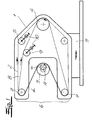
- Fig. 1 shows a device for finishing a shaft.
- the Device comprises a tool carrier 1, an endless sanding belt 2 for Finish machining of a rotationally driven about its axis of rotation A.
- Workpiece 3 a sanding belt drive 4, which the sanding belt 2 during a workpiece machining continuously drives, and a clamping device 5 for the sanding belt 2.
- the tool carrier 1 has a machining head 6 with two mutually spaced band deflections 7, the one Limit working area L of the machining head 6.
- the band deflections 7 are formed as pulleys.
- the sanding belt 2 is guided over the pulleys 7 and runs in the work area L to the machining peripheral surface of the workpiece 3 over.
- Supporting belt 8 is provided, which in the working area L of the machining head 6 is stretched parallel to the sanding belt 2 and in the work area L the Rear side of the sanding belt 2 is supported.
- the machining head 6 surrounds the processing peripheral surface of the workpiece 3 so that the back of The support belt 8 acted upon abrasive belt 2, the workpiece 3 partially wraps around and along a peripheral portion of the processed Workpiece surface rests flat.
- the support band 8 is by means of a separate second clamping device 9 stretched. This second tensioning device 9 allows a targeted adjustment of the exerted by the abrasive belt 2 on the workpiece 3 Surface force.
- the mechanical stress on the abrasive belt 2 is caused by the support belt. 8 significantly reduced, so no special requirements for tensile strength of the abrasive belt 2 must be made.
- the sanding belt drive allows a targeted adjustment of the cutting speed on the working surface. The for the achievement of good finisher results required high cutting speeds are thus even at small Workpiece diameters possible.
- the support band 8 is in the embodiment made of metal, but may alternatively be made of an elastic material consist. The support belt 8 is together with the sanding belt 2 over the Work area L limiting pulleys 7 out and is in Embodiment of FIG.
- the two clamping devices 5, 9, the Both bands 2.8 and the sanding belt drive 4 are common on the Workpiece carrier 1 is arranged.
- the tensioning devices 5.9 have adjusting devices 10 for changing the tape lengths in the working area L. Of the Wrap angle ⁇ between the grinding belt 2 and the machined Workpiece surface is more than 90 ° in the embodiment. This is a very uniform workpiece machining possible.
- the tool carrier 1 is mounted on a feed carriage 11.
- Fig. 2 shows a further embodiment of the invention Contraption.
- the tool holder 1 follows here the orbital motion of its axis of rotation A rotating workpiece 3, which in Fig. 2 as Crankshaft is formed.
- Bearing shafts 12, 12 'are provided, whose shape corresponds to the workpiece 3.
- the tool carrier 1 is on peripheral surfaces 13, 13 'of Bearing shafts 12, 12 'mounted, the surface to be machined of the workpiece 3 correspond.
- a separate support belt drive 14 is provided, which continuously drives the support belt 8.
- the rectified ones Belt speeds of sanding belt 2 and support belt 8 are also in this Embodiment identical.
- the tool carrier is the first pivotally mounted about a rotation axis C, which is parallel to the rotation axis A. of the workpiece 3 is aligned and in one between the machining head 6 and the grinding belt drive 4 lying tool carrier area arranged is. Trained as a swivel arm tool carrier 1 can by an oscillating pivoting movement of the rotating workpiece surfaces of the Crankshaft 3 follow, with the contact area between abrasive belt 2 and workpiece 3 within the work area L during the orbital motion moves accordingly. Due to the simple construction and Operation, this embodiment allows a particularly cost-effective Finish machining of crankshafts and camshafts.
- the distance of the sanding belt drive 4 of the axis of rotation C of the tool carrier 1 is set so that a substantial mass balance of the about the rotation axis C given vibrating masses. Furthermore, one is along the tool carrier 1 slidably arranged mass 15 is provided before the Beginning of processing at a specific position of the tool carrier. 1 lockable, so that the desired contact force between abrasive belt 2 and workpiece surface is ensured during processing. Also in this Embodiment, the support band 8 is also continuously with the same Direction of movement and speed as the sanding belt 2 of the Sanding belt drive 4 driven.
Landscapes
- Engineering & Computer Science (AREA)
- Mechanical Engineering (AREA)
- Finish Polishing, Edge Sharpening, And Grinding By Specific Grinding Devices (AREA)
- Grinding And Polishing Of Tertiary Curved Surfaces And Surfaces With Complex Shapes (AREA)
Abstract
Die Erfindung betrifft ein Verfahren zur Finisbearbeitung von Wellen, insbes.
von Kurbel- und Nockenwellen, bei dem eine Werkstückfläche eines um seine
Rotationsachse rotierenden Werkstückes mit Hilfe eines kontinuierlich angetriebenen
endlosen Schleifbandes bearbeitet wird. Das Schleifband wird mit
einer Spannvorrichtung gespannt und an seiner Rückseite im Bereich der
Werkstückfläche von einem endlosen, in diesem Bereich parallel zum Schleifband
gespannten Stützband gestützt. Erfindungsgemäß wird das Werkstück
von dem Schleifband und dem Stützband teilweise umschlungen, so dass das
Schleifband am Umfang des Werkstückes flächig anliegt. Das Stützband wird
mittels einer zweiten Spannvorrichtung gespannt. Gegenstand der Erfindung ist
auch eine Vorrichtung zur Durchführung des Verfahrens.

Description
Die Erfindung betrifft ein Verfahren zur Finishbearbeitung von Wellen, insbes. von Kurbel- und Nockenwellen, wobei eine Werkstückfläche eines um seine Rotationsachse rotierenden Werkstückes mit Hilfe eines kontinuierlich angetriebenen endlosen Schleifbandes bearbeitet wird und wobei das Schleifband mit einer Spannvorrichtung gespannt und an seiner Rückseite im Bereich der Werkstückfläche von einem endlosen, in diesem Bereich parallel zum Schleifband gespannten Stützband gestützt wird.The invention relates to a method for finishing of waves, esp. of crankshafts and camshafts, with a workpiece surface one around its Rotary axis rotating workpiece with the help of a continuously driven endless sanding belt is processed and where the sanding belt tensioned with a tensioning device and at its rear in the area of Work piece surface of an endless, in this area parallel to the sanding belt strained support band is supported.
Ein Verfahren mit den eingangs beschriebenen Merkmalen ist aus der Druckschrift US 5,951,377 bekannt. Bei dem bekannten Verfahren erfolgt zwischen dem Schleifband und dem zu bearbeitenden Werkstück eine in einer Schnittebene senkrecht zur Rotationsachse punktförmige Berührung. Das Schleifband wird im Bereich der zu bearbeitenden Werkstückfläche zwischen zwei Umlenkrollen geführt, die auch das Stützband spannen.A method with the features described above is from the document US 5,951,377. In the known method takes place between the grinding belt and the workpiece to be machined one in a cutting plane perpendicular to the axis of rotation punctiform contact. The sanding belt is in the area of the workpiece surface to be machined between two pulleys led, which also stretch the support band.
Der Erfindung liegt die Aufgabe zugrunde, ein Verfahren zur Finishbearbeitung von Wellen, insbes. von Kurbel- und Nockenwellen anzugeben, das eine gleichmäßige und auf die zu bearbeitende Werkstückfläche gezielt abstimmbare Finishbearbeitung ermöglicht.The invention is based on the object, a method for finishing of shafts, esp. Of crankshafts and camshafts specify that a uniform and specifically tunable to the workpiece surface to be machined Finish machining possible.
Ausgehend von einem Verfahren mit den eingangs beschriebenen Merkmalen wird die Aufgabe erfindungsgemäß dadurch gelöst, dass das Schleifband und das Stützband das Werkstück teilweise umschlingen, so dass das Schleifband am Umfang des Werkstückes flächig anliegt, und dass das Stützband mittels einer separaten zweiten Spannvorrichtung gespannt wird. Bei dem erfindungsgemäßen Verfahren liegt das Schleifband flächig mit gleichmäßiger Flächenpressung an der zu bearbeitenden Werkstückfläche an, wobei die Anpresskraft des Schleifbandes durch die separate Spannvorrichtung des Stützbandes gezielt einstellbar ist. Ferner erlaubt der Schleifbandantrieb eine gezielte Abstimmung der Schnittgeschwindigkeit auf die zu bearbeitende Oberfläche. Insbes. sind auch bei kleinen Werkstückdurchmessern hohe Schnittgeschwindigkeiten, welche für die Gewährleistung von guten Finishergebnissen erforderlich sind, einstellbar. Im Ergebnis ermöglicht das erfindungsgemäße Verfahren eine Finishbearbeitung von Werkstückflächen, die hohen Anforderungen an die Oberflächengüte entsprechen.Based on a method with the features described above the object is achieved in that the abrasive belt and the support band partially loop around the workpiece so that the abrasive belt flat against the circumference of the workpiece, and that the support band means a separate second clamping device is tensioned. In the inventive Procedure is the abrasive belt area with uniform surface pressure on the workpiece surface to be machined, wherein the contact pressure of the sanding belt by the separate tensioning device of the support band is specifically adjustable. Furthermore, the sanding belt drive allows a targeted Matching the cutting speed to the surface to be processed. Esp. are high cutting speeds even with small workpiece diameters which for ensuring good finisher results are required, adjustable. As a result, the inventive allows Process a finish machining of workpiece surfaces, the high Meet the requirements for surface quality.
Das Stützband besteht vorzugsweise aus einem zugfesten Material mit hohem Elastizitätsmodul, beispielsweise einem Metall. Die Verwendung eines Stützbandes, das aus einem elastomeren Material besteht und dehnbar ist, soll jedoch nicht ausgeschlossen sein.The support band is preferably made of a high tensile material Young's modulus, for example a metal. The use of a support band, which is made of an elastomeric material and is stretchable, should but not be excluded.
Das Stützband kann maschinenfest gespannt werden. Gemäß einer bevorzugten Ausführung der Erfindung wird das Stützband ebenfalls kontinuierlich und mit gleicher Bewegungsrichtung wie das Schleifband abgetrieben. Hierdurch kann die mechanische Beanspruchung des Schleifbandes reduziert werden, so dass auch Schleifbänder mit geringer Zugfestigkeit eingesetzt werden können. Vorzugsweise entspricht die Geschwindigkeit des Stützbandes der Geschwindigkeit des Schleifbandes.The support belt can be tensioned machine-resistant. According to a preferred Embodiment of the invention, the support belt is also continuous and driven off with the same direction of movement as the grinding belt. hereby can reduce the mechanical stress on the sanding belt be used so that also abrasive belts with low tensile strength can be. Preferably, the speed of the support belt corresponds the speed of the sanding belt.
Das Schleifband kann mit einem Umschlingungswinkel von mehr als 90° flächig an der zu bearbeitenden Umfangsfläche des Werkstückes an. Dies erlaubt eine sehr gleichmäßige Bearbeitung des Werkstückes.The abrasive belt can with a wrap angle of more than 90 ° flat on the machined peripheral surface of the workpiece. This allows a very uniform machining of the workpiece.
Gegenstand der Erfindung ist auch eine Vorrichtung zur Durchführung des
Verfahrens gemäß Anspruch 8. Bevorzugte Ausführungen dieser Vorrichtung
sind in den Ansprüchen 9 bis 12 beschrieben. The invention also provides a device for carrying out the
Method according to
Im Folgenden wird die Erfindung anhand einer lediglich ein Ausführungsbeispiel darstellenden Zeichnung ausführlich erläutert. Es zeigen schematisch:
- Fig. 1
- eine Seitenansicht einer erfindungsgemäßen Vorrichtung zur Finisbearbeitung von Wellen,
- Fig. 2 und 3
- weitere Ausgestaltungen der erfindungsgemäßen Vorrichtung ebenfalls in einer Seitenansicht.
- Fig. 1
- a side view of a device according to the invention for Finisbearbeitung of waves,
- FIGS. 2 and 3
- Further embodiments of the device according to the invention also in a side view.
Die Fig. 1 zeigt eine Vorrichtung zur Finishbearbeitung einer Welle. Die
Vorrichtung weist einen Werkzeugträger 1, ein endloses Schleifband 2 zur
Finishbearbeitung eines um seine Rotationsachse A rotierend angetriebenen
Werkstückes 3, einen Schleifbandantrieb 4, welcher das Schleifband 2 während
einer Werkstückbearbeitung kontinuierlich antreibt, und eine Spannvorrichtung
5 für das Schleifband 2 auf. Der Werkzeugträger 1 besitzt einen Bearbeitungskopf
6 mit zwei zueinander beabstandeten Bandumlenkungen 7, die einen
Arbeitsbereich L des Bearbeitungskopfes 6 begrenzen. Im Ausführungsbeispiel
sind die Bandumlenkungen 7 als Umlenkrollen ausgebildet. Das Schleifband 2
wird über die Umlenkrollen 7 geführt und läuft im Arbeitsbereich L an der zu
bearbeitenden Umfangsfläche des Werkstückes 3 vorbei. Ferner ist ein endloses
Stützband 8 vorgesehen, welches im Arbeitsbereich L des Bearbeitungskopfes
6 parallel zum Schleifband 2 gespannt ist und im Arbeitsbereich L die
Rückseite des Schleifbandes 2 abstützt. Der Bearbeitungskopf 6 umgreift die zu
bearbeitende Umfangsfläche des Werkstückes 3 so, dass das rückseitig von
dem Stützband 8 beaufschlagte Schleifband 2 das Werkstück 3 teilweise
umschlingt und entlang eines Umfangsabschnittes an der zu bearbeitenden
Werkstückfläche flächig anliegt. Das Stützband 8 ist mit Hilfe einer separaten
zweiten Spannvorrichtung 9 gespannt. Diese zweite Spannvorrichtung 9 erlaubt
eine gezielte Einstellung der von dem Schleifband 2 auf das Werkstück 3 ausgeübten
Flächenkraft. Diese Flächenkraft verläuft darüber hinaus über die
gesamte Kontaktfläche zwischen Schleifband 2 und Werkstück 3 hinweg sehr
gleichmäßig. Hierdurch sind sehr gute Finishergebnisse erzielbar. Die
mechanische Beanspruchung des Schleifbandes 2 wird durch das Stützband 8
erheblich reduziert, so dass keine besonderen Anforderungen an die Zugfestigkeit
des Schleifbandes 2 gestellt werden müssen. Der Schleifbandantrieb
erlaubt eine gezielte Abstimmung der Schnittgeschwindigkeit auf die zu
bearbeitende Oberfläche. Die für die Erzielung von guten Finishergebnissen
erforderlichen hohen Schnittgeschwindigkeiten sind damit auch bei kleinen
Werkstückdurchmessern möglich. Das Stützband 8 besteht im Ausführungsbeispiel
aus Metall, kann alternativ aber auch aus einem elastischen Material
bestehen. Das Stützband 8 ist zusammen mit dem Schleifband 2 über die den
Arbeitsbereich L begrenzenden Umlenkrollen 7 geführt und wird im
Ausführungsbeispiel gemäß Fig. 1 ebenfalls von dem Schleifbandantrieb 4
angetrieben. Im Ausführungsbeispiel ist die gleichgerichtete Geschwindigkeit
der beiden Bänder 2, 8 identisch, so dass im Arbeitsbereich L zwischen dem
Schleifband 2 und dem Stützband 8 nur eine sehr geringe bzw. keine Relativbewegung
vorliegt. Hierdurch ist eine besonders geringe Zugbeanspruchung
des Schleifbandes 2 gewährleistet. Die beiden Spannvorrichtungen 5, 9, die
beiden Bänder 2,8 und der Schleifbandantrieb 4 sind gemeinsam auf dem
Werkstückträger 1 angeordnet. Die Spannvorrichtungen 5,9 weisen Stelleinrichtungen
10 zur Veränderung der Bandlängen im Arbeitsbereich L auf. Der
Umschlingungswinkel α zwischen dem Schleifband 2 und der zu bearbeitenden
Werkstückfläche beträgt im Ausführungsbeispiel mehr als 90°. Hierdurch ist
eine sehr gleichmäßige Werkstückbearbeitung möglich. Der Werkzeugträger 1
ist auf einem Zustellschlitten 11 montiert.Fig. 1 shows a device for finishing a shaft. The
Device comprises a tool carrier 1, an
Die Fig. 2 zeigt eine weitere Ausgestaltung der erfindungsgemäßen
Vorrichtung. Der Werkzeugträger 1 folgt hier der Umlaufbewegung des um
seine Rotationsachse A rotierenden Werkstückes 3, welches in der Fig. 2 als
Kurbelwelle ausgebildet ist. Es sind zwei parallel zum Werkstück 3 angeordnete
Lagerwellen 12, 12' vorgesehen, deren Gestalt dem Werkstück 3 entspricht. Die
Lagerwellen 12, 12' rotieren synchron und phasengleich zum Werkstück 3 um
ihre Achsen B, B'. Der Werkzeugträger 1 ist an Umfangsflächen 13, 13' der
Lagerwellen 12, 12' gelagert, die der zu bearbeitenden Fläche des Werkstückes
3 entsprechen. In Fig. 2 ist ein separater Stützbandantrieb 14 vorgesehen,
welcher das Stützband 8 kontinuierlich antreibt. Die gleichgerichteten
Bandgeschwindigkeiten von Schleifband 2 und Stützband 8 sind auch in diesem
Ausführungsbeispiel identisch.Fig. 2 shows a further embodiment of the invention
Contraption. The tool holder 1 follows here the orbital motion of
its axis of rotation A rotating
Bei der in der Fig. 3 dargestellten Ausführungsform ist der Werkzeugträger 1
schwenkbar um eine Drehachse C gelagert, die parallel zur Rotationsachse A
des Werkstückes 3 ausgerichtet ist und in einem zwischen dem Bearbeitungskopf
6 und dem Schleifbandantrieb 4 liegenden Werkzeugträgerbereich angeordnet
ist. Der als Schwenkarm ausgebildete Werkzeugträger 1 kann durch
eine oszillierende Schwenkbewegung den umlaufenden Werkstückflächen der
Kurbelwelle 3 folgen, wobei sich der Kontaktbereich zwischen Schleifband 2
und Werkstück 3 innerhalb des Arbeitsbereiches L während der Umlaufbewegung
entsprechend verschiebt. Aufgrund der einfachen Konstruktion und
Betriebsweise erlaubt diese Ausführungsform eine besonders kostengünstige
Finishbearbeitung von Kurbel- und Nockenwellen. Der Abstand des Schleifbandantriebes
4 von der Drehachse C des Werkzeugträgers 1 ist so festgelegt,
dass ein weitgehender Massenausgleich der um die Drehachse C
schwingenden Massen gegeben ist. Ferner ist eine entlang des Werkzeugträgers
1 verschiebbar angeordnete Masse 15 vorgesehen, die vor dem
Bearbeitungsbeginn an einer bestimmten Position des Werkzeugträgers 1
arretierbar ist, so dass die gewünschte Anpresskraft zwischen Schleifband 2
und Werkstückfläche während der Bearbeitung gewährleistet ist. Auch in dieser
Ausführungsform wird das Stützband 8 ebenfalls kontinuierlich mit gleicher
Bewegungsrichtung und Geschwindigkeit wie das Schleifband 2 von dem
Schleifbandantrieb 4 angetrieben.In the embodiment shown in FIG. 3, the tool carrier is the first
pivotally mounted about a rotation axis C, which is parallel to the rotation axis A.
of the
Claims (12)
Werkzeugträger (1),
endlosem Schleifband (2) zur Finishbearbeitung eines um seine Rotationsachse (A) rotierend angetriebenen Werkstückes (3),
einem Schleifbandantrieb (4), welcher das Schleifband (2) während einer Werkstückbearbeitung kontinuierlich antreibt und
einer Spannvorrichtung (5) für das Schleifband (2),
wobei der Werkzeugträger (1) einen Bearbeitungskopf (6) mit zwei zueinander beabstandeten Bandumlenkungen (7) aufweist, die einen Arbeitsbereich (L) des Bearbeitungskopfes (6) begrenzen, wobei das Schleifband (2) über die Bandumlenkungen (7) des Bearbeitungskopfes (6) geführt ist und wobei ein endloses Stützband (8) vorgesehen ist, welches im Arbeitsbereich (L) des Bearbeitungskopfes (6) parallel zum Schleifband (2) gespannt ist und im Arbeitsbereich (L) die Rückseite des Schleifbandes (2) abstützt, dadurch gekennzeich net, dass der Bearbeitungskopf (6) die zu bearbeitende Umfangsfläche des Werkstückes(3) gabelförmig so umgreift, dass das rückseitig von dem Stützband (8) beaufschlagte Schleifband (2) das Werkstück (3) teilweise umschlingt und entlang eines Umfangsabschnittes an der zu bearbeitenden Werkstückfläche flächig anliegt, und dass das Stützband (8) mit Hilfe einer separaten zweiten Spannvorrichtung (9) gespannt ist. Apparatus for carrying out the method according to one of claims 1 to 7 with
Tool carrier (1),
endless grinding belt (2) for finish machining of a workpiece (3) driven in rotation about its axis of rotation (A),
a sanding belt drive (4) which continuously drives the sanding belt (2) during workpiece machining, and
a tensioning device (5) for the sanding belt (2),
the tool carrier (1) having a machining head (6) with two mutually spaced band deflections (7) delimiting a working area (L) of the machining head (6), the sanding belt (2) being moved over the band deflections (7) of the machining head (6 ) is guided and wherein an endless support belt (8) is provided which in the work area (L) of the machining head (6) is stretched parallel to the sanding belt (2) and in the work area (L) the back of the abrasive belt (2) is supported, characterized gekennzeich Net , that the machining head (6) so engages the peripheral surface of the workpiece (3) to be machined so that the back of the support belt (8) acted upon abrasive belt (2) partially wraps around the workpiece (3) and along a peripheral portion of the machined Plane surface is applied flat, and that the support band (8) by means of a separate second clamping device (9) is stretched.
Applications Claiming Priority (2)
| Application Number | Priority Date | Filing Date | Title |
|---|---|---|---|
| DE10342134 | 2003-09-12 | ||
| DE2003142134 DE10342134B4 (en) | 2003-09-12 | 2003-09-12 | Method and device for finishing crankshafts and camshafts |
Publications (3)
| Publication Number | Publication Date |
|---|---|
| EP1514640A2 true EP1514640A2 (en) | 2005-03-16 |
| EP1514640A3 EP1514640A3 (en) | 2006-03-01 |
| EP1514640B1 EP1514640B1 (en) | 2010-05-26 |
Family
ID=34129774
Family Applications (1)
| Application Number | Title | Priority Date | Filing Date |
|---|---|---|---|
| EP20040020483 Expired - Lifetime EP1514640B1 (en) | 2003-09-12 | 2004-08-28 | Method and apparatus for finishing shafts, especially crank- and camshafts |
Country Status (2)
| Country | Link |
|---|---|
| EP (1) | EP1514640B1 (en) |
| DE (2) | DE10342134B4 (en) |
Cited By (13)
| Publication number | Priority date | Publication date | Assignee | Title |
|---|---|---|---|---|
| WO2007081289A1 (en) * | 2006-01-09 | 2007-07-19 | Giken Sakata (S) Limited | An apparatus for grinding a work piece |
| WO2009049868A1 (en) * | 2007-10-16 | 2009-04-23 | Nagel Maschinen- Und Werkzeugfabrik Gmbh | Pressing device for cutting means and apparatus and method for finishing circumferential surfaces on cylindrical parts of a workpiece |
| CN103213042A (en) * | 2012-01-23 | 2013-07-24 | 德国索菲纳有限公司 | Device for finely processing a peripheral area of the workpiece fixed in an eccentric manner to a peripheral area of a workpiece |
| CN104139333A (en) * | 2014-07-11 | 2014-11-12 | 山东金宝电子股份有限公司 | Grinding method for rubber layer of rubber roller of copper foil surface treatment machine and arc plate fixture used thereof |
| EP3103587A1 (en) * | 2015-05-07 | 2016-12-14 | Jakob Löwer Inh. von Schumann GmbH & Co. KG | Deburring machine for deburring metallic workpieces |
| CN106425768A (en) * | 2016-09-23 | 2017-02-22 | 杭州新松机器人自动化有限公司 | Abrasive belt floating polishing mechanism |
| CN106863077A (en) * | 2015-11-09 | 2017-06-20 | 德国索菲纳有限公司 | Finishing belting and workpiece method for fine finishing |
| CN107953207A (en) * | 2017-12-26 | 2018-04-24 | 佛山市艾乐博机器人科技有限公司 | A kind of grinding apparatus and its processing method |
| CN108044728A (en) * | 2018-01-18 | 2018-05-18 | 杨月君 | A kind of process units of winding-type circle template and winding-type circle template |
| CN108177061A (en) * | 2018-01-16 | 2018-06-19 | 苏州丰川电子科技有限公司 | Automate metal surface treating apparatus |
| CN110026867A (en) * | 2019-05-05 | 2019-07-19 | 宁波梦创知识产权服务有限公司 | A kind of multi-angle processing roller manufacturing device |
| CN115464519A (en) * | 2022-10-26 | 2022-12-13 | 王鑫 | System for removing oxide layer on surface of metal wire |
| CN117564890A (en) * | 2023-11-24 | 2024-02-20 | 宁波中策动力机电集团有限公司 | A following abrasive belt crankshaft grinder and control method |
Families Citing this family (4)
| Publication number | Priority date | Publication date | Assignee | Title |
|---|---|---|---|---|
| DE102010052311A1 (en) | 2010-11-17 | 2012-05-24 | Nagel Maschinen- Und Werkzeugfabrik Gmbh | Method and device for finishing curved workpiece surfaces on workpieces by means of finishing tape |
| DE102011081918A1 (en) | 2011-08-31 | 2013-02-28 | Nagel Maschinen- Und Werkzeugfabrik Gmbh | Finishing machine for finishing curved workpiece surfaces on workpieces |
| TWI725225B (en) * | 2017-08-30 | 2021-04-21 | 日商荏原製作所股份有限公司 | Grinding device and grinding method |
| CN112059852A (en) * | 2020-09-30 | 2020-12-11 | 王后连 | Polishing belt type strip steel side burr removing device |
Family Cites Families (7)
| Publication number | Priority date | Publication date | Assignee | Title |
|---|---|---|---|---|
| DE7424571U (en) * | 1974-10-17 | Krugmann Gjt | Grinding device | |
| DE844420C (en) * | 1951-01-06 | 1952-07-21 | Ernst Ebner | Belt grinder |
| DE3020393A1 (en) * | 1980-05-29 | 1982-01-28 | Friedr. August Picard KG, 5630 Remscheid | Endless band grinder unit - has band supported on resilient endless belt running around support disc with spaced projections on disc surface |
| US5951377A (en) * | 1996-08-01 | 1999-09-14 | Radtec, Inc. | Microfinishing machine |
| JPH11165249A (en) * | 1997-12-05 | 1999-06-22 | Tocalo Co Ltd | Belt type polishing device |
| US6220946B1 (en) * | 1998-02-13 | 2001-04-24 | Philip D. Arnold | Active polishing of rotatable article surfaces |
| DE10342137B4 (en) * | 2003-09-12 | 2010-07-29 | Thielenhaus Technologies Gmbh | Apparatus and method for finish machining of shafts, in particular crankshafts and camshafts |
-
2003
- 2003-09-12 DE DE2003142134 patent/DE10342134B4/en not_active Expired - Fee Related
-
2004
- 2004-08-28 DE DE200450011200 patent/DE502004011200D1/en not_active Expired - Lifetime
- 2004-08-28 EP EP20040020483 patent/EP1514640B1/en not_active Expired - Lifetime
Cited By (27)
| Publication number | Priority date | Publication date | Assignee | Title |
|---|---|---|---|---|
| WO2007081289A1 (en) * | 2006-01-09 | 2007-07-19 | Giken Sakata (S) Limited | An apparatus for grinding a work piece |
| CN101370618B (en) * | 2006-01-09 | 2010-08-25 | 技研阪田股份有限公司 | Apparatus for grinding workpieces |
| WO2009049868A1 (en) * | 2007-10-16 | 2009-04-23 | Nagel Maschinen- Und Werkzeugfabrik Gmbh | Pressing device for cutting means and apparatus and method for finishing circumferential surfaces on cylindrical parts of a workpiece |
| CN101903130A (en) * | 2007-10-16 | 2010-12-01 | 纳格尔机械及工具制造厂有限责任公司 | Pressing device for cutting member, and apparatus and method for polishing circumferential surface of cylindrical workpiece portion |
| CN106425773A (en) * | 2007-10-16 | 2017-02-22 | 纳格尔机械及工具制造厂有限责任公司 | Pressing device for cutting means and apparatus and method for finishing circumferential surfaces on cylindrical parts of a workpiece |
| DE102007051047B4 (en) | 2007-10-16 | 2023-03-23 | Nagel Maschinen- Und Werkzeugfabrik Gmbh | Press-on device for finishing belt and device and method for finishing peripheral surfaces on cylindrical workpiece sections |
| EP2212058B2 (en) † | 2007-10-16 | 2018-03-28 | Nagel Maschinen- und Werkzeugfabrik GmbH | Pressing device for cutting means and apparatus and method for finishing circumferential surfaces on cylindrical parts of a workpiece |
| US8517804B2 (en) | 2007-10-16 | 2013-08-27 | Nagel Maschinen- Und Werkzeugfabrik Gmbh | Pressing device for cutting means and apparatus and method for finishing circumferential surfaces on cylindrical parts of a workpiece |
| KR20130086172A (en) * | 2012-01-23 | 2013-07-31 | 숩피나 그리에샤버 게엠베하 & 씨오. 케이쥐 | Apparatus for finely processing surrounding surface of workpiece eccentrically disposed with respect to workpiece axis of workpiece |
| US9114497B2 (en) | 2012-01-23 | 2015-08-25 | Supfina Grieshaber Gmbh & Co. Kg | Device for fine-machining a peripheral workpiece surface located eccentrically in relation to a workpiece axis of a workpiece |
| CN103213042B (en) * | 2012-01-23 | 2016-01-20 | 德国索菲纳有限公司 | For the accurately machined equipment of workpiece ring side face to the axis of workpiece eccentric setting about workpiece |
| EP2617522A1 (en) * | 2012-01-23 | 2013-07-24 | Supfina Grieshaber GmbH & Co. KG | Device for finely processing a peripheral area of the workpiece fixed in an eccentric manner to a peripheral area of a workpiece |
| CN103213042A (en) * | 2012-01-23 | 2013-07-24 | 德国索菲纳有限公司 | Device for finely processing a peripheral area of the workpiece fixed in an eccentric manner to a peripheral area of a workpiece |
| CN104139333B (en) * | 2014-07-11 | 2016-05-18 | 山东金宝电子股份有限公司 | The method for grinding of copper foil surface processor rubber roll glue-line and the arc board clamp of use thereof |
| CN104139333A (en) * | 2014-07-11 | 2014-11-12 | 山东金宝电子股份有限公司 | Grinding method for rubber layer of rubber roller of copper foil surface treatment machine and arc plate fixture used thereof |
| EP3103587A1 (en) * | 2015-05-07 | 2016-12-14 | Jakob Löwer Inh. von Schumann GmbH & Co. KG | Deburring machine for deburring metallic workpieces |
| CN106863077A (en) * | 2015-11-09 | 2017-06-20 | 德国索菲纳有限公司 | Finishing belting and workpiece method for fine finishing |
| CN106425768B (en) * | 2016-09-23 | 2018-06-01 | 杭州新松机器人自动化有限公司 | A kind of abrasive band floating workpiece polishing mechanism |
| CN106425768A (en) * | 2016-09-23 | 2017-02-22 | 杭州新松机器人自动化有限公司 | Abrasive belt floating polishing mechanism |
| CN107953207A (en) * | 2017-12-26 | 2018-04-24 | 佛山市艾乐博机器人科技有限公司 | A kind of grinding apparatus and its processing method |
| CN108177061A (en) * | 2018-01-16 | 2018-06-19 | 苏州丰川电子科技有限公司 | Automate metal surface treating apparatus |
| CN108044728A (en) * | 2018-01-18 | 2018-05-18 | 杨月君 | A kind of process units of winding-type circle template and winding-type circle template |
| CN108044728B (en) * | 2018-01-18 | 2023-08-25 | 天津银雪环保科技服务有限公司 | Winding type round template and production device of winding type round template |
| CN110026867A (en) * | 2019-05-05 | 2019-07-19 | 宁波梦创知识产权服务有限公司 | A kind of multi-angle processing roller manufacturing device |
| CN115464519A (en) * | 2022-10-26 | 2022-12-13 | 王鑫 | System for removing oxide layer on surface of metal wire |
| CN115464519B (en) * | 2022-10-26 | 2024-02-13 | 天津市春鹏预应力钢绞线有限公司 | System for removing oxide layer on surface of metal wire |
| CN117564890A (en) * | 2023-11-24 | 2024-02-20 | 宁波中策动力机电集团有限公司 | A following abrasive belt crankshaft grinder and control method |
Also Published As
| Publication number | Publication date |
|---|---|
| EP1514640A3 (en) | 2006-03-01 |
| EP1514640B1 (en) | 2010-05-26 |
| DE10342134A1 (en) | 2005-04-07 |
| DE10342134B4 (en) | 2009-09-03 |
| DE502004011200D1 (en) | 2010-07-08 |
Similar Documents
| Publication | Publication Date | Title |
|---|---|---|
| EP1514640B1 (en) | Method and apparatus for finishing shafts, especially crank- and camshafts | |
| DE60000670T2 (en) | Belt grinding machine with grinding belt moving around one orbit | |
| DE202008018526U1 (en) | Pressing device for Schmittel and device for finishing peripheral surfaces on cylindrical workpiece sections | |
| DE4493442B4 (en) | Continuous grinding machine, especially designed for grinding wood and intermediate grinding of paint on cover plates, etc., which are mainly flat workpieces | |
| EP1990133B1 (en) | Grinder as tool for a processing device | |
| DE19723306C2 (en) | Method and device for grinding or polishing end faces of plate-shaped bodies | |
| EP3135433A2 (en) | Surface processing unit, machine tool and method of operating | |
| EP0276439B1 (en) | Method for grinding internally long bores with extremly small diameter in pieces and device for carrying out this method | |
| EP2636482B1 (en) | Workpiece processing system and method for detailed processing of a workpiece | |
| DE4227315C2 (en) | Machine for grinding, short stroke honing and polishing the outer surface of workpieces | |
| DE69410527T2 (en) | Belt grinder for cylindrical workpieces | |
| DE10342139B4 (en) | Process for finishing peripheral surfaces on wave-shaped workpieces | |
| DE19821982C2 (en) | Profile belt grinder | |
| EP1514641A1 (en) | Apparatus for Finishing Shafts, particularly Crank- and Camshafts | |
| DE102017201120B3 (en) | Pressure device for finishing belt and belt finishing device | |
| DE10342137B4 (en) | Apparatus and method for finish machining of shafts, in particular crankshafts and camshafts | |
| DE10041925A1 (en) | Grinding process involves bringing workpiece and grinding agent into engagement with feed movement as well as vibrating movement which differs from feed direction | |
| DE202009004809U1 (en) | Pipe grinding machine with adjustable side guide of the sanding belt | |
| DE102006000829B3 (en) | Apparatus for removing the burr of die-cast ceramic articles | |
| DE2556170B2 (en) | Grinding or polishing device for a gear | |
| DE4105799A1 (en) | Grinding outer surface of tube - using two spaced abrasive bands wrapped round tube and reciprocated out of phase by linear end drives | |
| EP1920884B1 (en) | Method for strip finishing of workpiece peripheral surfaces | |
| DE102009025784A1 (en) | Pipe drilling machine, has clamping roller rotated around clamping roller axis and movably supported at clamping roller frame at side such that roller is aligned along running direction of drilling band at different angular positions | |
| DE1181504B (en) | Device for sharpening the ends of single or multi-layer drive belts or conveyor belts to be made endless | |
| DE2346431A1 (en) | METHOD AND DEVICE FOR GRINDING A SURFACE |
Legal Events
| Date | Code | Title | Description |
|---|---|---|---|
| PUAI | Public reference made under article 153(3) epc to a published international application that has entered the european phase |
Free format text: ORIGINAL CODE: 0009012 |
|
| AK | Designated contracting states |
Kind code of ref document: A2 Designated state(s): AT BE BG CH CY CZ DE DK EE ES FI FR GB GR HU IE IT LI LU MC NL PL PT RO SE SI SK TR |
|
| AX | Request for extension of the european patent |
Extension state: AL HR LT LV MK |
|
| PUAL | Search report despatched |
Free format text: ORIGINAL CODE: 0009013 |
|
| AK | Designated contracting states |
Kind code of ref document: A3 Designated state(s): AT BE BG CH CY CZ DE DK EE ES FI FR GB GR HU IE IT LI LU MC NL PL PT RO SE SI SK TR |
|
| AX | Request for extension of the european patent |
Extension state: AL HR LT LV MK |
|
| 17P | Request for examination filed |
Effective date: 20060318 |
|
| AKX | Designation fees paid |
Designated state(s): DE FR GB IT |
|
| 17Q | First examination report despatched |
Effective date: 20090514 |
|
| GRAP | Despatch of communication of intention to grant a patent |
Free format text: ORIGINAL CODE: EPIDOSNIGR1 |
|
| GRAS | Grant fee paid |
Free format text: ORIGINAL CODE: EPIDOSNIGR3 |
|
| GRAA | (expected) grant |
Free format text: ORIGINAL CODE: 0009210 |
|
| AK | Designated contracting states |
Kind code of ref document: B1 Designated state(s): DE FR GB IT |
|
| REG | Reference to a national code |
Ref country code: GB Ref legal event code: FG4D Free format text: NOT ENGLISH |
|
| REF | Corresponds to: |
Ref document number: 502004011200 Country of ref document: DE Date of ref document: 20100708 Kind code of ref document: P |
|
| PLBE | No opposition filed within time limit |
Free format text: ORIGINAL CODE: 0009261 |
|
| STAA | Information on the status of an ep patent application or granted ep patent |
Free format text: STATUS: NO OPPOSITION FILED WITHIN TIME LIMIT |
|
| 26N | No opposition filed |
Effective date: 20110301 |
|
| REG | Reference to a national code |
Ref country code: DE Ref legal event code: R097 Ref document number: 502004011200 Country of ref document: DE Effective date: 20110228 |
|
| PGFP | Annual fee paid to national office [announced via postgrant information from national office to epo] |
Ref country code: GB Payment date: 20110830 Year of fee payment: 8 Ref country code: FR Payment date: 20110912 Year of fee payment: 8 Ref country code: DE Payment date: 20110830 Year of fee payment: 8 |
|
| PGFP | Annual fee paid to national office [announced via postgrant information from national office to epo] |
Ref country code: IT Payment date: 20110831 Year of fee payment: 8 |
|
| GBPC | Gb: european patent ceased through non-payment of renewal fee |
Effective date: 20120828 |
|
| REG | Reference to a national code |
Ref country code: FR Ref legal event code: ST Effective date: 20130430 |
|
| PG25 | Lapsed in a contracting state [announced via postgrant information from national office to epo] |
Ref country code: IT Free format text: LAPSE BECAUSE OF NON-PAYMENT OF DUE FEES Effective date: 20120828 |
|
| PG25 | Lapsed in a contracting state [announced via postgrant information from national office to epo] |
Ref country code: DE Free format text: LAPSE BECAUSE OF NON-PAYMENT OF DUE FEES Effective date: 20130301 Ref country code: GB Free format text: LAPSE BECAUSE OF NON-PAYMENT OF DUE FEES Effective date: 20120828 |
|
| PG25 | Lapsed in a contracting state [announced via postgrant information from national office to epo] |
Ref country code: FR Free format text: LAPSE BECAUSE OF NON-PAYMENT OF DUE FEES Effective date: 20120831 |
|
| REG | Reference to a national code |
Ref country code: DE Ref legal event code: R119 Ref document number: 502004011200 Country of ref document: DE Effective date: 20130301 |