EP1514571A2 - Support pour un dispositif médical de perforation et système de pompe à sang - Google Patents
Support pour un dispositif médical de perforation et système de pompe à sang Download PDFInfo
- Publication number
- EP1514571A2 EP1514571A2 EP04021479A EP04021479A EP1514571A2 EP 1514571 A2 EP1514571 A2 EP 1514571A2 EP 04021479 A EP04021479 A EP 04021479A EP 04021479 A EP04021479 A EP 04021479A EP 1514571 A2 EP1514571 A2 EP 1514571A2
- Authority
- EP
- European Patent Office
- Prior art keywords
- penetrating
- skin
- medical
- holder
- penetrating object
- Prior art date
- Legal status (The legal status is an assumption and is not a legal conclusion. Google has not performed a legal analysis and makes no representation as to the accuracy of the status listed.)
- Granted
Links
Images


Classifications
-
- A—HUMAN NECESSITIES
- A61—MEDICAL OR VETERINARY SCIENCE; HYGIENE
- A61M—DEVICES FOR INTRODUCING MEDIA INTO, OR ONTO, THE BODY; DEVICES FOR TRANSDUCING BODY MEDIA OR FOR TAKING MEDIA FROM THE BODY; DEVICES FOR PRODUCING OR ENDING SLEEP OR STUPOR
- A61M25/00—Catheters; Hollow probes
- A61M25/01—Introducing, guiding, advancing, emplacing or holding catheters
- A61M25/02—Holding devices, e.g. on the body
-
- A—HUMAN NECESSITIES
- A61—MEDICAL OR VETERINARY SCIENCE; HYGIENE
- A61B—DIAGNOSIS; SURGERY; IDENTIFICATION
- A61B50/00—Containers, covers, furniture or holders specially adapted for surgical or diagnostic appliances or instruments, e.g. sterile covers
- A61B50/10—Furniture specially adapted for surgical or diagnostic appliances or instruments
- A61B50/13—Trolleys, e.g. carts
-
- A—HUMAN NECESSITIES
- A61—MEDICAL OR VETERINARY SCIENCE; HYGIENE
- A61M—DEVICES FOR INTRODUCING MEDIA INTO, OR ONTO, THE BODY; DEVICES FOR TRANSDUCING BODY MEDIA OR FOR TAKING MEDIA FROM THE BODY; DEVICES FOR PRODUCING OR ENDING SLEEP OR STUPOR
- A61M1/00—Suction or pumping devices for medical purposes; Devices for carrying-off, for treatment of, or for carrying-over, body-liquids; Drainage systems
- A61M1/36—Other treatment of blood in a by-pass of the natural circulatory system, e.g. temperature adaptation, irradiation ; Extra-corporeal blood circuits
- A61M1/3621—Extra-corporeal blood circuits
- A61M1/3653—Interfaces between patient blood circulation and extra-corporal blood circuit
- A61M1/3659—Cannulae pertaining to extracorporeal circulation
- A61M1/3661—Cannulae pertaining to extracorporeal circulation for haemodialysis
-
- A—HUMAN NECESSITIES
- A61—MEDICAL OR VETERINARY SCIENCE; HYGIENE
- A61M—DEVICES FOR INTRODUCING MEDIA INTO, OR ONTO, THE BODY; DEVICES FOR TRANSDUCING BODY MEDIA OR FOR TAKING MEDIA FROM THE BODY; DEVICES FOR PRODUCING OR ENDING SLEEP OR STUPOR
- A61M60/00—Blood pumps; Devices for mechanical circulatory actuation; Balloon pumps for circulatory assistance
- A61M60/10—Location thereof with respect to the patient's body
- A61M60/122—Implantable pumps or pumping devices, i.e. the blood being pumped inside the patient's body
- A61M60/165—Implantable pumps or pumping devices, i.e. the blood being pumped inside the patient's body implantable in, on, or around the heart
- A61M60/178—Implantable pumps or pumping devices, i.e. the blood being pumped inside the patient's body implantable in, on, or around the heart drawing blood from a ventricle and returning the blood to the arterial system via a cannula external to the ventricle, e.g. left or right ventricular assist devices
-
- A—HUMAN NECESSITIES
- A61—MEDICAL OR VETERINARY SCIENCE; HYGIENE
- A61M—DEVICES FOR INTRODUCING MEDIA INTO, OR ONTO, THE BODY; DEVICES FOR TRANSDUCING BODY MEDIA OR FOR TAKING MEDIA FROM THE BODY; DEVICES FOR PRODUCING OR ENDING SLEEP OR STUPOR
- A61M60/00—Blood pumps; Devices for mechanical circulatory actuation; Balloon pumps for circulatory assistance
- A61M60/20—Type thereof
- A61M60/205—Non-positive displacement blood pumps
- A61M60/216—Non-positive displacement blood pumps including a rotating member acting on the blood, e.g. impeller
- A61M60/221—Non-positive displacement blood pumps including a rotating member acting on the blood, e.g. impeller the blood flow through the rotating member having both radial and axial components, e.g. mixed flow pumps
-
- A—HUMAN NECESSITIES
- A61—MEDICAL OR VETERINARY SCIENCE; HYGIENE
- A61M—DEVICES FOR INTRODUCING MEDIA INTO, OR ONTO, THE BODY; DEVICES FOR TRANSDUCING BODY MEDIA OR FOR TAKING MEDIA FROM THE BODY; DEVICES FOR PRODUCING OR ENDING SLEEP OR STUPOR
- A61M60/00—Blood pumps; Devices for mechanical circulatory actuation; Balloon pumps for circulatory assistance
- A61M60/20—Type thereof
- A61M60/205—Non-positive displacement blood pumps
- A61M60/216—Non-positive displacement blood pumps including a rotating member acting on the blood, e.g. impeller
- A61M60/226—Non-positive displacement blood pumps including a rotating member acting on the blood, e.g. impeller the blood flow through the rotating member having mainly radial components
- A61M60/232—Centrifugal pumps
-
- A—HUMAN NECESSITIES
- A61—MEDICAL OR VETERINARY SCIENCE; HYGIENE
- A61M—DEVICES FOR INTRODUCING MEDIA INTO, OR ONTO, THE BODY; DEVICES FOR TRANSDUCING BODY MEDIA OR FOR TAKING MEDIA FROM THE BODY; DEVICES FOR PRODUCING OR ENDING SLEEP OR STUPOR
- A61M60/00—Blood pumps; Devices for mechanical circulatory actuation; Balloon pumps for circulatory assistance
- A61M60/20—Type thereof
- A61M60/205—Non-positive displacement blood pumps
- A61M60/216—Non-positive displacement blood pumps including a rotating member acting on the blood, e.g. impeller
- A61M60/237—Non-positive displacement blood pumps including a rotating member acting on the blood, e.g. impeller the blood flow through the rotating member having mainly axial components, e.g. axial flow pumps
-
- A—HUMAN NECESSITIES
- A61—MEDICAL OR VETERINARY SCIENCE; HYGIENE
- A61B—DIAGNOSIS; SURGERY; IDENTIFICATION
- A61B90/00—Instruments, implements or accessories specially adapted for surgery or diagnosis and not covered by any of the groups A61B1/00 - A61B50/00, e.g. for luxation treatment or for protecting wound edges
- A61B90/50—Supports for surgical instruments, e.g. articulated arms
-
- A—HUMAN NECESSITIES
- A61—MEDICAL OR VETERINARY SCIENCE; HYGIENE
- A61M—DEVICES FOR INTRODUCING MEDIA INTO, OR ONTO, THE BODY; DEVICES FOR TRANSDUCING BODY MEDIA OR FOR TAKING MEDIA FROM THE BODY; DEVICES FOR PRODUCING OR ENDING SLEEP OR STUPOR
- A61M1/00—Suction or pumping devices for medical purposes; Devices for carrying-off, for treatment of, or for carrying-over, body-liquids; Drainage systems
- A61M1/14—Dialysis systems; Artificial kidneys; Blood oxygenators ; Reciprocating systems for treatment of body fluids, e.g. single needle systems for hemofiltration or pheresis
- A61M1/28—Peritoneal dialysis ; Other peritoneal treatment, e.g. oxygenation
-
- A—HUMAN NECESSITIES
- A61—MEDICAL OR VETERINARY SCIENCE; HYGIENE
- A61M—DEVICES FOR INTRODUCING MEDIA INTO, OR ONTO, THE BODY; DEVICES FOR TRANSDUCING BODY MEDIA OR FOR TAKING MEDIA FROM THE BODY; DEVICES FOR PRODUCING OR ENDING SLEEP OR STUPOR
- A61M25/00—Catheters; Hollow probes
- A61M25/01—Introducing, guiding, advancing, emplacing or holding catheters
- A61M25/02—Holding devices, e.g. on the body
- A61M2025/0206—Holding devices, e.g. on the body where the catheter is secured by using devices worn by the patient, e.g. belts or harnesses
-
- A—HUMAN NECESSITIES
- A61—MEDICAL OR VETERINARY SCIENCE; HYGIENE
- A61M—DEVICES FOR INTRODUCING MEDIA INTO, OR ONTO, THE BODY; DEVICES FOR TRANSDUCING BODY MEDIA OR FOR TAKING MEDIA FROM THE BODY; DEVICES FOR PRODUCING OR ENDING SLEEP OR STUPOR
- A61M39/00—Tubes, tube connectors, tube couplings, valves, access sites or the like, specially adapted for medical use
- A61M39/02—Access sites
- A61M39/0247—Semi-permanent or permanent transcutaneous or percutaneous access sites to the inside of the body
-
- A—HUMAN NECESSITIES
- A61—MEDICAL OR VETERINARY SCIENCE; HYGIENE
- A61M—DEVICES FOR INTRODUCING MEDIA INTO, OR ONTO, THE BODY; DEVICES FOR TRANSDUCING BODY MEDIA OR FOR TAKING MEDIA FROM THE BODY; DEVICES FOR PRODUCING OR ENDING SLEEP OR STUPOR
- A61M60/00—Blood pumps; Devices for mechanical circulatory actuation; Balloon pumps for circulatory assistance
- A61M60/10—Location thereof with respect to the patient's body
- A61M60/122—Implantable pumps or pumping devices, i.e. the blood being pumped inside the patient's body
- A61M60/126—Implantable pumps or pumping devices, i.e. the blood being pumped inside the patient's body implantable via, into, inside, in line, branching on, or around a blood vessel
- A61M60/148—Implantable pumps or pumping devices, i.e. the blood being pumped inside the patient's body implantable via, into, inside, in line, branching on, or around a blood vessel in line with a blood vessel using resection or like techniques, e.g. permanent endovascular heart assist devices
Definitions
- the present invention relates to a skin-penetrating medical object holder for holding a medical skin-penetrating object such as a tube, cable, or a catheter that passes through the skin of a living body, and to a blood pump system equipped with this skin-penetrating medical object holder.
- a medical skin-penetrating object such as a tube, cable, or a catheter that passes through the skin of a living body
- a medical skin-penetrating object such as a tube, cable, or catheter that passes through the skin of a living body is used to connect the internal organ of the living body or the artificial organ and external medical equipment.
- an artificial heart can be used during and following heart surgery, or a variety of medical treatments, such as dialysis, peritoneal dialysis (hereinafter, "PD"), or the use of a drug delivery system, can be carried out.
- PD peritoneal dialysis
- drug delivery system can be carried out.
- the bonding forces between the living body tissue near the skin and the surface of the tube are weak, so that external forces can easily detach the surface of the tube or the like from the living body tissue. Bacteria can enter the skin tissue at such parts, thereby causing infections. For this reason, it is necessary to take measures to make it difficult for external forces to act on the tube entry part, with this being an important step in the prevention of infections.
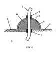
- FIG 15 is a cross-sectional view useful in explaining this fixing construction.
- the fixing construction 1 is a medical assembly that prevents bacteria from entering a living body from a tube entry part where a tube 2 passes through the skin, and includes a sticking part 4, which is stuck onto the opening edge (the skin) 3 of the tube entry part, a covering 6 which holds and covers the tube entry part and forms an internal space 5, a tube holding part 7 for holding the tube 2 on the living body side, and a tube holding part 8 for holding the tube 2 that passes therethrough.
- the fixing construction 1 makes it difficult for the tube 2 that passes through the skin of a living body to move, so that even if external forces are applied to the tube 2, detachment of the tube 2 from the living body tissue due to external forces is suppressed, which is effective in preventing infections. Additionally, when this fixing construction 1 is used, the internal space 5 of the covering 6 can be filled with medication M, so that infections can be suppressed even more effectively.
- the present invention was conceived in response to the demands described above and it is an object of the present invention to provide a skin-penetrating medical object holder that can effectively suppress detachment of a medical skin-penetrating object and living body tissue due to external forces and therefore can prevent infections from occurring from the outset.
- the blood pump system of the present invention includes a skin-penetrating medical object holder that can prevent the occurrence of infections from the outset, and so is a blood pump system suited to treatment following an operation that implants a blood pump.
- a skin-penetrating medical object holder and a blood pump system to which the present invention has been applied will be described below based on embodiments shown in the attached drawings.
- a skin-penetrating medical object holder will be described with reference to FIGS. 1A to 6.
- FIGS. 1A and 1B show a skin-penetrating medical object holder according to an embodiment of the present invention, with FIG. 1A is being a front elevation and FIG. 1B being a rear elevation.
- FIG. 2 is a front elevation showing a state where the skin-penetrating medical object holder according to an embodiment of the present invention has been opened out in the length direction.
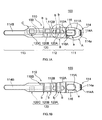
- FIGS. 3A and 3B are front elevations showing an enlargement of the part A in FIG. 1A, with FIG. 3A being a front elevation showing a state where an edge member has been attached and FIG. 3B being a front elevation showing a state where the edge member has been separated.
- FIGS. 4A and 4B are front elevations showing an enlargement of the part B in FIG.
- FIG. 4A being a front elevation showing a state where a penetrating object holding part has been folded back
- FIG. 4B being a front elevation showing a state where the penetrating object holding part has been opened
- FIGS. 5A and 5B are front elevations showing an enlargement of a penetrating object holding part in part C in FIG. 1A
- FIG. 5A being a front elevation showing a state where the penetrating object holding part has been folded back
- FIG. 5B being a front elevation showing a state where the penetrating object holding part has been opened.
- FIG. 6 is a perspective view showing a state where the skin-penetrating medical object holder according to an embodiment of the present invention has been wound around a living body.
- a skin-penetrating medical object holder 100 includes a holder main body 110 and a penetrating object holding means 120, and is formed by an abdominal belt composed of a woven material (as one example, a textile material in the present embodiment).
- a textile material a material composed of FIRBEST FIBER (a registered trademark of FIRBEST CO. LTD) including ceramic particles that absorb and radiate far-infrared radiation can favorably be used.
- the skin-penetrating medical object holder 100 can absorb far-infrared radiation from the living body and moisture such as sweat can also be effectively dispersed from the skin-penetrating medical object holder 100. As a result, a warm, comfortable feel can be achieved during use, and inflammation and the like of the skin of the living body can be prevented. Also, since the skin-penetrating medical object holder 100 can be easily washed, the skin-penetrating medical object holder 100 can always be used in a clean state.
- reference numeral 110A in FIG. 1A designates a region for displaying a logo mark
- reference numeral 110B in FIG. 1B designates a region for displaying information such as a size.
- the holder main body 110 includes three holder parts 111 to 113, and as shown in FIG. 6 is formed of a belt-like member that can be wound around a living body (such as a human body). This means that the holder main body 110 can be wound around the living body in accordance with the shape of the wearing part on the living body. For this reason, the winding force of the holder main body 110 on the living body can be increased.
- the holder main body 110 is subjected to a stitching process to make the holder thickness at the outer edge parts thicker than the holder thickness at the center part. By doing so, the outer edge parts of the holder main body 110 can be reinforced relative to the center part of the holder main body 110. This means that the holder main body 110 can be prevented from losing its shape.
- a holder tightening means 114 is also disposed on the holder main body 110 to tighten the holder main body 110 on the living body.
- the length L (the unstretched length) of the holder main body 110 in the length direction is set at 980mm, and the width W (maximum value) in the width direction is set at 140mm. It should be noted that the length of the holder main body 110 in the length direction can be set as appropriate for the dimensions of the wearing part on the living body.
- the holder parts 111 to 113 are disposed in a row in the length direction and are set with respectively different dimensions (external forms) in the length and width directions.
- the holder part 111 is composed of an inelastic part in the shape of a curve so as to protrude in an up-down direction for the holder main body 110, and is disposed at one end (the right end in FIG. 1) of the holder main body 110.
- a locking member 114A is disposed at the front end (the free end) of the holder part 111 as a holder locking part that composes part of the holder tightening means 114. As shown in FIGS. 3A and 3B, this locking member 114A is formed of a substantially rectangular frame with a through hole 114a.
- the locking member 114A is attached to the holder part 111 by passing the end part of the holder part 111 through the through hole 114a, folding back the end part, and stitching the folded-back part to the non-folded back part of the holder part 111.
- the holder part 111 includes a penetrating object passage hole 111A that allows a medical skin-penetrating object 150 to pass through and a penetrating object guiding path 111B for guiding the medical skin-penetrating object 150 within the penetrating object passage hole 111A, with an edge member 116 being stitched to an edge of the penetrating object passage hole 111A, the edge member 116 being attachable and detachable via fasteners 111a, 116A so as to open and close the penetrating object guiding path 111B.
- reference numeral 116B designates a seam of the edge member 116.
- the insertion of the medical skin-penetrating object 150 into the penetrating object passage hole 111A is carried out by separating the edge member 116 from the edge of the penetrating object passage hole 111A to open the penetrating object guiding path 111B and guiding the medical skin-penetrating object 150 into the penetrating object passage hole 111A from the penetrating object guiding path 111B. It should be noted that after the medical skin-penetrating object 150 has been inserted into the penetrating object passage hole 111A, the edge member 116 is combined with the edge of the penetrating object passage hole 111A.
- edge member 116 is attachable and detachable via fasteners 111a, 116A
- the present invention is not limited to this and an edge member may be attachable and detachable via buttons, strings, clasps such as hooks, magnets, buckles or the like.
- the penetrating object passage hole 111A is constructed so as to function as a penetrating object passage hole for conducting a medical treatment.
- a medical treatment such as application of medication
- a medical assembly (not shown) that is stuck onto the living body can be disposed within the penetrating object passage hole 111A and a medical treatment can be carried out via this medical assembly.
- the "fixing construction" disclosed by Yamazaki and Mori in Japanese Laid-Open Patent Publication No. 2000-140125 can be used.
- a substantially J-shaped wire-like member (not shown) is embedded at a position shown by the arrows a in FIGS. 3A and 3B.
- the skin-penetrating medical object holder 100 (the holder main body 110) is also constructed so as to be reinforced. By doing so, the edge periphery of the penetrating object passage hole 111A is reinforced. This means that the holder main body 110 can be prevented from losing its shape.
- the front end of the wire-like member should preferably be composed of a flexible member.
- the holder part 112 is composed of a linear-shaped elastic part that is elastic in at least the length direction and is disposed in a central position of the holder main body 110. By doing so, when the holder part 112 stretches as shown in FIG. 2, the stretching part is tightly wound around the living body. This means that the winding force of the holder main body 110 with respect to the living body can be increased.
- the holder main body 110 has an elastic part so that it is possible to wind a holder main body 110 of the same length around living bodies of different physiques.
- An opening 112A for exposing a supplementary holder (not shown) to the outside is provided at a penetrating object passage hole of the holder part 112, the supplementary holder sticking to the living body and holding the medical skin-penetrating object 150 in concert with the penetrating object holding means 120.
- the medical skin-penetrating object 150 is held by the penetrating object holding means 120 and the supplementary holder. By doing so, it is possible to more favorably hold the medical skin-penetrating object 150 on the holder main body 110.
- an extra opening 112B is provided in a line with and at a predetermined distance from the opening 112A in the holder length direction (on an opposite side of the holder part 111).
- the medical skin-penetrating object 150 can be held not only by the penetrating object holding means 120 but also by the supplementary holder (not shown) that sticks to the living body and is exposed from the extra opening 112B. This means that it is possible to avoid having the supplementary holder stuck to the same part of the living body for a long period, so that inflammation and the like of the skin of the living body can be prevented.
- the opening size of the openings 112A, 112B should preferably be set with consideration to the pressing of the supplementary holder onto the living body (by the edge parts of the openings 112A, 112B) when the holder main body 110 is wound and to the ease with which the supplementary holder can be stuck onto the living body.
- the sizes of the openings 112A, 112B are too small, although there will be a sufficient contact surface area for pressing the supplementary holder onto the living body, it will become difficult to stick the supplementary holder onto the living body.
- the sizes of the openings 112A, 112B are too large, although it will become easier to stick the supplementary holder onto the living body, a sufficient contact surface area for pressing the supplementary holder onto the living body will not be achieved.
- wire-like members which are oriented in the width direction of the holder, for achieving tight contact between the living body and the holder are embedded.
- These wire-like members are formed by a plurality of loop members disposed in a row in the length direction of the holder with predetermined distances in between.
- the holder part 113 is composed of two inelastic parts with respectively different widths, and is disposed at the other end of the holder main body 110.
- a fastener 114B is disposed as a holder attaching part that in concert with the locking member 114A composes the holder tightening means 114.
- one end of the holder main body 110 (the holder part 113) that is locked by (passes through) the locking member 114A and is folded back is constructed so as to be attachable and detachable.
- the holder main body 110 can be tightened on the living body by the holder tightening means 114 by winding one part (a middle part) of the holder main body 110 around the living body, passing the holder main body 110 (the holder part 113) through the through hole 114a to lock the holder main body 110 with the locking member 114A, and finally folding back the holder part 113 and attaching the fastener 114B.
- the holder main body 110 is tightened to the living body when the holder part 113 is attached to the fastener 114B. This means that it is possible to easily and reliably tighten the holder main body 110 using the holder tightening means 114.
- the penetrating object holding means 120 is composed of a penetrating object holding means that holds the medical skin-penetrating object 150, which is passed through the skin of the living body, on the outside of the living body, and is disposed on the holder main body 110 (the holder parts 112, 113).
- the penetrating object holding means 120 is constructed so as to guide the medical skin-penetrating object 150 along the length of the holder main body 110 in the wound state for the holder.
- the penetrating object holding means 120 includes a plurality of penetrating object holding parts 120A to 120C that are aligned at predetermined intervals along the length direction of the holder main body 110.
- the penetrating object holding parts 120A to 120C should preferably be disposed at positions so that the medical skin-penetrating object 150 is guided around at least one half circumference of the wearing part of the living body. By doing so, a state where the medical skin-penetrating object 150 is stably held on the living body is achieved.
- the number of penetrating object holding parts 120A to 120C can be set as appropriate in accordance with the size of the holder main body 110 in the length direction.
- the number can be set as appropriate in accordance with the length of the holder.
- the lengths of the penetrating object holding parts are also set as appropriate in accordance with the length of the holder.
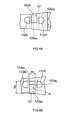
- the penetrating object holding means 120 of the skin-penetrating medical object holder 100 is composed of a single penetrating object holding part as shown in FIG. 7, the length of the penetrating object holding part in the holder length direction should preferably be increased.
- the holder main body 110 is wound around the living body as shown in FIG. 8. By doing so, external forces that act on the medical skin-penetrating object 150 are absorbed by the entire penetrating object holding part (the penetrating object holding means 120) that extends in the length direction of the holder main body 110.
- the penetrating object holding part should preferably be disposed at positions so that the medical skin-penetrating object 150 is guided around at least one half circumference of the wearing part of the living body. By doing so, a state where the medical skin-penetrating object 150 is stably held on the living body is achieved.
- the length of the penetrating object holding part is also set as appropriate in accordance with the holder length.
- the penetrating object holding parts 120A to 120C are disposed at substantially the same height as the height of the position where the medical skin-penetrating object 150 passes through the skin of the living body. By doing so, the penetrating object holding parts 120A to 120C can be wound around the wearing part of the living body at substantially the same height as the part at which the medical skin-penetrating object 150 passes through the skin of the living body. This means that the load applied from the medical skin-penetrating object 150 to the part where the object passes through the epidermis of the living body can be further reduced. By doing so, it is possible to effectively suppress detachment of the medical skin-penetrating object 150 and the living body tissue due to external forces, so that infections can be prevented from the outset even more effectively.
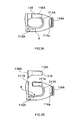
- the penetrating object holding part 120A includes two attaching parts 120a 1 , 120a 2 that can be detachably attached to each other and a penetrating object contacting part 120a 3 that can be opened up and folded back via both attaching parts 120a1, 120a2, and is disposed between the two openings 112A, 112B.
- the width w 1 of the penetrating object holding part 120A in the left-right direction is set at 45mm and the width w 2 in the up-down direction in an opened-up state for the penetrating object contacting part 120a 3 is set at 96mm.
- One attaching part 120a 1 out of the attaching parts 120a 1 , 120a 2 is attached to an upper end of a surface of the holder part 112, with a grasping tab 121 used during attachment and detachment being disposed on the other attaching part 120a 2 .
- the penetrating object contacting part 120a 3 is composed so as to be formed in a tube-like form through which the medical skin-penetrating object 150 passes when both attaching parts 120a 1 , 120a 2 are in the attached state.
- the medical skin-penetrating object 150 is placed in contact with the penetrating object contacting part 120a 3 and the attaching parts 120a 1 , 120a 2 are attached to one another by folding back the penetrating object contacting part 120a 3 with the imaginary line shown by the symbol m in FIG. 4B, for example, as the folding back line.
- the attaching parts 120a 1 , 120a 2 are attached to one another, the penetrating object contacting part 120a 3 is formed in a tube-like part, with the medical skin-penetrating object 150 being held by this tube-like part.
- a surface treatment to prevent the medical skin-penetrating object 150 from slipping is carried out on the penetrating object contacting part 120a 3 . By doing so, it is possible to stop the medical skin-penetrating object 150 slipping in the penetrating object contacting part 120a 3 . This means that it is possible to improve the holding of the medical skin-penetrating object 150 on the holder main body 110 by the penetrating object holding part 120A.
- the penetrating object holding parts 120B and 120C have substantially the same construction (with only the attachment positions differing), and therefore of these, only the penetrating object holding part 120C will be described as a representative example.
- the penetrating object holding part 120C includes two attaching parts 120c 1 , 120c 2 that can be detachably attached to each other and a penetrating object contacting part 120c 3 that is opened up and folded back via both attaching parts 120c 1 , 120c 2 .
- the width w 3 of the penetrating object holding part 120C in the left-right direction is set at 60mm and the width w 4 in the up-down direction in an opened-up state for the penetrating object contacting part 120c 3 is set at 96mm.
- One attaching part 120c 1 out of the attaching parts 120c 1 , 120c 2 is attached to an upper end edge of a surface of the holder part 113.
- a grasping tab 122 used during attachment and detachment is disposed on the other attaching part 120c 2 .
- the penetrating object contacting part 120c 3 is composed so as to be formed in a tube-like form through which the medical skin-penetrating object 150 passes when both attaching parts 120c 1 , 120c 2 are in the attached state.
- the medical skin-penetrating object 150 is placed in contact with the penetrating object contacting part 120c 3 and the attaching parts 120c 1 , 120c 2 are attached to one another by folding back the penetrating object contacting part 120c 3 with the imaginary line shown by the symbol n in FIG. 5, for example, as the folding back line.
- the attaching parts 120c 1 , 120c 2 are attached to one another, the penetrating object contacting part 120c 3 is formed in a tube-like part, with the medical skin-penetrating object 150 being held by this tube-like part.
- a surface treatment to prevent the medical skin-penetrating object 150 from slipping is carried out on the penetrating object contacting part 120c 3 . By doing so, it is possible to stop the medical skin-penetrating object 150 slipping in the penetrating object contacting part 120c 3 . This means that it is possible to improve the holding of the medical skin-penetrating object 150 onto the holder main body 110 by the penetrating object holding part 120C.
- a surface treatment such as formation of a polyurethane coating on nylon tricot or an acryl coating on polyester tricot, or attachment of a silicon sheet or chamois can be given as examples of the treatment carried out for the penetrating object contacting part 120c 3 .
- the above penetrating object holding means preferably includes attaching parts composed of a fastener, for example.
- the above penetrating object holding means may include attaching parts having buttons, strings, clasps such as hooks, magnets, buckles or the like.
- the above penetrating object holding means may be composed of a clip in which the medical skin-penetrating object is caught, a partly cut ring through which medical skin-penetrating object is inserted, or the like.
- the above penetrating object holding means should preferably be such means that the medical skin-penetrating object can be hold in any way.
- the holder main body 110 of the skin-penetrating medical object holder 100 is wound around the living body and the medical skin-penetrating object 150 is held by the penetrating object holding means 120, so that even if an external force is applied to the medical skin-penetrating object 150 due to movement of the living body or handling of the medical skin-penetrating object 150, the external force will be received and absorbed by the penetrating object holding means 120 together with the holder main body 110 wound around the living body.
- the skin-penetrating medical object holder 100 is wound around the abdominal part of a human body H as an abdominal belt, a cross-section of the abdominal part is divided into four regions H 1 to H 4 (four substantially equal parts) by two perpendicular imaginary lines X and Y, and the skin-penetrating medical object holder 100 is wound so as to guide the medical skin-penetrating object 150 across positions (the epidermis) corresponding to these four regions H 1 to H 4 , the medical skin-penetrating object 150 will be stably held on the human body H, so that detachment of the medical skin-penetrating object 150 and the living body tissue due to an external force is effectively prevented, which means that infections can be prevented even more effectively.
- the holding of the medical skin-penetrating object 150 by the penetrating object holding part h 1 near the entry point is most important, with the holding of the medical skin-penetrating object 150 by the penetrating object holding parts h 2 , h 3 where the curvature of the human body is greatest (where the curvature of the medical skin-penetrating object 150 is also large) being next in importance.
- the greatest effect is achieved in the case where the medical skin-penetrating object 150 is held by a single penetrating object holding part or a plurality of penetrating object holding parts from the entry point of the medical skin-penetrating object 150 into the living body to the penetrating object holding part h 4 , that is, around at least one half circumference of the living body.
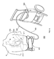
- FIG. 10 is a perspective view useful in explaining a blood pump system that uses the skin-penetrating medical object holder 100 according to the present embodiment.
- a blood pump system 200 includes a blood pump 210 that is implanted in a living body, an external controller 220 for driving and controlling the blood pump 210, the medical skin-penetrating object 150 that is used to connect the blood pump 210 and the external controller 220, and the skin-penetrating medical object holder 100 for holding the medical skin-penetrating object 150.
- the blood pump 210 includes a pump driving unit 211 and a pump unit 212 and is constructed so that blood in the left ventricle A of the heart of the human body H flows into a pump casing 213 from an intake of the pump casing 213, is energized with flow energy by pump vanes (not shown) inside the pump casing 213, and then flows through an outlet of the pump casing 213 and an artificial blood vessel C implanted in the human body to the aorta B.
- a centrifugal pump, an axial-flow pump, a mixed-flow pump, or the like can be favorably used as the blood pump 210.
- the external controller 220 includes a circulating liquid pump unit that supplies a circulating liquid to a periphery of a mechanical seal of the blood pump 210, a pump control unit that drives and controls the circulating liquid pump unit and the blood pump 210, a display unit that displays the operating states of the various components, a communication unit that exchanges information with external devices, a power supplying unit that supplies these components with electrical power, and a system control unit for controlling these components (none of such components are shown).
- the medical skin-penetrating object 150 includes an inner tube for circulating liquid such as pure water between the blood pump 210 and the external controller 220, a cable that electrically connects the blood pump 210 and the external controller 220, and an outer tube that encloses the cable and the inner tube (none of such components are shown). By doing so, it is possible to safely and smoothly carry out treatment using the medical skin-penetrating object 150 after an operation that implants the blood pump 210.
- the blood pump system 200 of the present embodiment uses the skin-penetrating medical object holder 100 that can prevent the occurrence of infections from the outset, the blood pump system 200 is suited to treatments carried out after an operation that implants the blood pump 210.
- the medical skin-penetrating object 150 is a medical skin-penetrating object used to connect the blood pump 210 implanted in the human body H and the external controller 220 used for driving and controlling the blood pump 210 has been described in the present embodiment, the present invention is not limited to this, and the medical skin-penetrating object 150 may be applied to a medical skin-penetrating object for circulating blood between a living body and a dialysis machine. In this case, it is possible to carry out dialysis treatment more safely and smoothly.
- the medical skin-penetrating object for the present invention can also be applied in the same way to a medical skin-penetrating object used for carrying out PD. In this case, it is possible to carry out PD treatment more safely and smoothly.
- the medical skin-penetrating object for the present invention can also be applied to a medical skin-penetrating object used in a drug delivery system. By doing so, it becomes possible to carry out treatment with a drug delivery system more safely and smoothly.
- the present invention is not limited to this and a supplementary holder 300 that is stuck to the living body may be exposed to the outside from the opening 112A of the holder part 112 shown in FIGS. 11 and 12, with the medical skin-penetrating object 150 being held by the supplementary holder 300 and the penetrating object holding parts 120A to 120C (only the penetrating object holding part 120A is shown).
- the supplementary holder 300 is pressed onto the living body by the periphery of the opening 112A (the holder main body 110), so that the supplementary holder 300 is firmly held on the living body and the medical skin-penetrating object 150 can be held even more stably on the living body. This means that detachment of the medical skin-penetrating object 150 and the living body tissue due to external forces can be effectively suppressed, so that infections can be effectively prevented from occurring.
- a medical assembly 400 for sticking onto the living body may be exposed to the outside from the penetrating object passage hole 111A of the holder part 111, with the medical skin-penetrating object 150 being held by the medical assembly 400 and the penetrating object holding parts 120A to 120C (only the penetrating object holding part 120A is shown).
- the supplementary holder 300 is pressed onto the living body by the edge of the opening 112A and the medical assembly 400 is pressed on the living body by the edge of the penetrating object passage hole 111A, so that the supplementary holder 300 and the medical assembly 400 are strongly held on the living body and a state where the medical skin-penetrating object 150 is held on the living body even more stably is realized. For this reason, detachment of the medical skin-penetrating object 150 and the living body tissue due to external forces can be suppressed more effectively, and infections can be prevented even more effectively.
- a skin-penetrating medical object holder can effectively suppress detachment of a medical skin-penetrating object and living body tissue due to external forces, and therefore can prevent infections from occurring from the outset.
- the skin-penetrating medical object holder includes a belt-like holder main body that is wound around a living body and a penetrating object holding part that is disposed on the holder main body and holds a medical skin-penetrating object that passes through the skin of the living body.
- the penetrating object holding part is constructed so as to guide, in a state where the holder main body has been wound around the living body, the medical skin-penetrating object along a length direction of the holder main body.
Landscapes
- Health & Medical Sciences (AREA)
- Heart & Thoracic Surgery (AREA)
- Engineering & Computer Science (AREA)
- Life Sciences & Earth Sciences (AREA)
- Animal Behavior & Ethology (AREA)
- Veterinary Medicine (AREA)
- Public Health (AREA)
- Biomedical Technology (AREA)
- General Health & Medical Sciences (AREA)
- Anesthesiology (AREA)
- Hematology (AREA)
- Cardiology (AREA)
- Mechanical Engineering (AREA)
- Vascular Medicine (AREA)
- Surgery (AREA)
- Molecular Biology (AREA)
- Medical Informatics (AREA)
- Biophysics (AREA)
- Pulmonology (AREA)
- Urology & Nephrology (AREA)
- Nuclear Medicine, Radiotherapy & Molecular Imaging (AREA)
- Media Introduction/Drainage Providing Device (AREA)
- External Artificial Organs (AREA)
Applications Claiming Priority (2)
| Application Number | Priority Date | Filing Date | Title |
|---|---|---|---|
| JP2003322168A JP4293870B2 (ja) | 2003-09-12 | 2003-09-12 | 医療用皮膚挿通具ホルダ及び血液ポンプシステム |
| JP2003322168 | 2003-09-12 |
Publications (3)
| Publication Number | Publication Date |
|---|---|
| EP1514571A2 true EP1514571A2 (fr) | 2005-03-16 |
| EP1514571A3 EP1514571A3 (fr) | 2007-03-07 |
| EP1514571B1 EP1514571B1 (fr) | 2012-01-18 |
Family
ID=34132071
Family Applications (1)
| Application Number | Title | Priority Date | Filing Date |
|---|---|---|---|
| EP04021479A Expired - Fee Related EP1514571B1 (fr) | 2003-09-12 | 2004-09-09 | Support pour un dispositif médical de perforation et système de pompe à sang |
Country Status (3)
| Country | Link |
|---|---|
| US (1) | US20050059935A1 (fr) |
| EP (1) | EP1514571B1 (fr) |
| JP (1) | JP4293870B2 (fr) |
Cited By (2)
| Publication number | Priority date | Publication date | Assignee | Title |
|---|---|---|---|---|
| IT201600115884A1 (it) * | 2016-11-17 | 2018-05-17 | Loreto Nico Di | dispositivo di contenimento per P.E.G. (Gastrostomia Endoscopica Percutanea) |
| US11311714B2 (en) * | 2017-02-02 | 2022-04-26 | Xenios Ag | Arrangement with a blood pump, a control unit and a device for transmitting the measured values |
Families Citing this family (13)
| Publication number | Priority date | Publication date | Assignee | Title |
|---|---|---|---|---|
| US20070235025A1 (en) * | 2006-04-10 | 2007-10-11 | Rachelle Fink | Baby hernia belt |
| US7661152B2 (en) * | 2007-03-07 | 2010-02-16 | Raul Manzano-Rivera | Gastrostomy garment |
| US9327099B2 (en) * | 2013-06-04 | 2016-05-03 | Spectrum Health Innovations, LLC | Medical tube harness |
| CN106334221A (zh) * | 2016-09-30 | 2017-01-18 | 张华伟 | 腹带式引流袋及引流管固定带 |
| CA3066361A1 (fr) | 2017-06-07 | 2018-12-13 | Shifamed Holdings, Llc | Dispositifs de deplacement de fluide intravasculaire, systemes et procedes d'utilisation |
| JP7319266B2 (ja) | 2017-11-13 | 2023-08-01 | シファメド・ホールディングス・エルエルシー | 血管内流体移動デバイス、システム、および使用方法 |
| EP3746149A4 (fr) | 2018-02-01 | 2021-10-27 | Shifamed Holdings, LLC | Pompes à sang intravasculaires et méthodes d'utilisation et procédés de fabrication |
| US11529508B2 (en) * | 2018-03-02 | 2022-12-20 | Tc1 Llc | Wearable accessory for ventricular assist system |
| JP2022540616A (ja) | 2019-07-12 | 2022-09-16 | シファメド・ホールディングス・エルエルシー | 血管内血液ポンプならびに製造および使用の方法 |
| WO2021016372A1 (fr) | 2019-07-22 | 2021-01-28 | Shifamed Holdings, Llc | Pompes à sang intravasculaires à entretoises et procédés d'utilisation et de fabrication |
| WO2021062265A1 (fr) | 2019-09-25 | 2021-04-01 | Shifamed Holdings, Llc | Dispositifs et systèmes de pompes à sang intravasculaires et leurs procédés d'utilisation et de commande |
| CN112402103A (zh) * | 2020-12-10 | 2021-02-26 | 张红波 | 一种可调节的棉蕊手术护垫 |
| JP2023163880A (ja) * | 2022-04-28 | 2023-11-10 | 株式会社ハイレックスコーポレーション | 固定構造 |
Citations (1)
| Publication number | Priority date | Publication date | Assignee | Title |
|---|---|---|---|---|
| JP2000140125A (ja) | 1998-09-04 | 2000-05-23 | San Medical Gijutsu Kenkyusho:Kk | 固定具 |
Family Cites Families (23)
| Publication number | Priority date | Publication date | Assignee | Title |
|---|---|---|---|---|
| US1948251A (en) * | 1931-11-09 | 1934-02-20 | Admiral L Andrews | Trousers support |
| US4096863A (en) * | 1975-09-11 | 1978-06-27 | Baka Manufacturing Company, Inc. | Band for anchoring a cathetor or any other tubular device to the body |
| US4429000A (en) * | 1979-12-11 | 1984-01-31 | Toray Industries, Inc. | Moisture-permeable waterproof coated fabric and method of making the same |
| US5048512A (en) * | 1985-04-16 | 1991-09-17 | Turner W Richard | Gastrostomy tube protector and hider |
| US4799923A (en) * | 1986-09-15 | 1989-01-24 | Myrna Campbell | Medical tube securing device |
| US4738661A (en) * | 1986-09-18 | 1988-04-19 | Marut Marie R | Gastrostomy belt |
| US4955867A (en) * | 1989-05-12 | 1990-09-11 | Endo Walter Y | Peritoneal dialysis catheter protector belt |
| US5205832A (en) * | 1990-04-06 | 1993-04-27 | Tuman David H | Endo-tracheal tube support device |
| US5271745A (en) * | 1992-10-27 | 1993-12-21 | Tabex Industries, Inc. | Medical tubing retaining device and method of use |
| US5495282A (en) * | 1992-11-03 | 1996-02-27 | The Arbitron Company | Monitoring system for TV, cable and VCR |
| US5425719A (en) * | 1993-05-27 | 1995-06-20 | Lessing, Jr.; Kennith C. | Peritoneal dialysis catheter belt pack |
| US5403285A (en) * | 1994-04-29 | 1995-04-04 | Roberts; Sandra L. | Apparatus for securing a catheter tube to a body |
| US5468229A (en) * | 1994-11-02 | 1995-11-21 | Chandler; Janice | Peritoneal dialysis catheter support belt |
| US5496282A (en) * | 1994-12-12 | 1996-03-05 | Militzer; George G. | Apparatus and method to stabilize a peritoneal dialysis catheter |
| US5728070A (en) * | 1995-02-03 | 1998-03-17 | Walker, Deceased; Herbert B. | Portable chemotherapy treatment dispenser system |
| US5626570A (en) * | 1996-06-11 | 1997-05-06 | Gallo; Kerry R. | Ostomy appliance belt |
| US5833655A (en) * | 1997-05-15 | 1998-11-10 | L. Vad Technology, Inc. | Percutaneous access device having removable turret assembly |
| US6735532B2 (en) * | 1998-09-30 | 2004-05-11 | L. Vad Technology, Inc. | Cardiovascular support control system |
| US6436074B1 (en) * | 1999-06-08 | 2002-08-20 | Jarrel Eugene Lee | Garment for securing and exposing a peritoneal dialysis catheter and catheter exit site |
| US20020052568A1 (en) * | 2000-09-28 | 2002-05-02 | Houser Russell A. | Joint braces and traction devices incorporating superelastic supports |
| US6544232B1 (en) * | 2000-07-18 | 2003-04-08 | Mcdaniel Gladys P. | Cystostomy catheter belt |
| US6267115B1 (en) * | 2000-09-25 | 2001-07-31 | Florine Marshel | Intravenous protecting device |
| JP4175558B2 (ja) * | 2002-07-23 | 2008-11-05 | 株式会社ファーベスト | 遠赤外線放射材料 |
-
2003
- 2003-09-12 JP JP2003322168A patent/JP4293870B2/ja not_active Expired - Fee Related
-
2004
- 2004-09-08 US US10/936,453 patent/US20050059935A1/en not_active Abandoned
- 2004-09-09 EP EP04021479A patent/EP1514571B1/fr not_active Expired - Fee Related
Patent Citations (1)
| Publication number | Priority date | Publication date | Assignee | Title |
|---|---|---|---|---|
| JP2000140125A (ja) | 1998-09-04 | 2000-05-23 | San Medical Gijutsu Kenkyusho:Kk | 固定具 |
Cited By (2)
| Publication number | Priority date | Publication date | Assignee | Title |
|---|---|---|---|---|
| IT201600115884A1 (it) * | 2016-11-17 | 2018-05-17 | Loreto Nico Di | dispositivo di contenimento per P.E.G. (Gastrostomia Endoscopica Percutanea) |
| US11311714B2 (en) * | 2017-02-02 | 2022-04-26 | Xenios Ag | Arrangement with a blood pump, a control unit and a device for transmitting the measured values |
Also Published As
| Publication number | Publication date |
|---|---|
| JP4293870B2 (ja) | 2009-07-08 |
| EP1514571B1 (fr) | 2012-01-18 |
| EP1514571A3 (fr) | 2007-03-07 |
| US20050059935A1 (en) | 2005-03-17 |
| JP2005087337A (ja) | 2005-04-07 |
Similar Documents
| Publication | Publication Date | Title |
|---|---|---|
| EP1514571B1 (fr) | Support pour un dispositif médical de perforation et système de pompe à sang | |
| US5637098A (en) | Catheter securement device | |
| US4582508A (en) | Garment for receiving catheters and the like | |
| US7181773B1 (en) | Hospital gown | |
| US20160050995A1 (en) | Medical garment | |
| US20090054844A1 (en) | Medical garment wrap | |
| US5468229A (en) | Peritoneal dialysis catheter support belt | |
| US9510627B2 (en) | Medical apron apparatus | |
| JP2005501652A (ja) | 心不全治療用装置 | |
| US9925358B2 (en) | Catheter stabilization device and method of use | |
| US20110023208A1 (en) | Patient -Worn Medical Tube (Cannula) Holder Vest And Apparatuses | |
| US20050020982A1 (en) | Medical device security band | |
| US20200376233A1 (en) | Line Protecting Garment | |
| SE1950298A1 (en) | Fixation device for an intravascular tube | |
| CN210096039U (zh) | 一种连袖可拆卸式约束手套 | |
| CN217525357U (zh) | 洞巾 | |
| CN219594996U (zh) | 一种固定腹部引流管腹带 | |
| CN214969766U (zh) | 一种医用引流管保护袋 | |
| CN212787563U (zh) | 一种透析患者防止皮肤过敏用导管固定背心 | |
| CN209749882U (zh) | 一种留置尿管患者的保暖裤 | |
| CN219593787U (zh) | 一种改良型腰椎手术病人服 | |
| CN210844674U (zh) | 一种留置针固定装置 | |
| CN215992860U (zh) | 一种术后携带引流管的患者病员裤 | |
| CN213667268U (zh) | 一种静脉留置针保护带 | |
| CN217219301U (zh) | 一种腹膜透析腰带 |
Legal Events
| Date | Code | Title | Description |
|---|---|---|---|
| PUAI | Public reference made under article 153(3) epc to a published international application that has entered the european phase |
Free format text: ORIGINAL CODE: 0009012 |
|
| AK | Designated contracting states |
Kind code of ref document: A2 Designated state(s): AT BE BG CH CY CZ DE DK EE ES FI FR GB GR HU IE IT LI LU MC NL PL PT RO SE SI SK TR |
|
| AX | Request for extension of the european patent |
Extension state: AL HR LT LV MK |
|
| PUAL | Search report despatched |
Free format text: ORIGINAL CODE: 0009013 |
|
| AK | Designated contracting states |
Kind code of ref document: A3 Designated state(s): AT BE BG CH CY CZ DE DK EE ES FI FR GB GR HU IE IT LI LU MC NL PL PT RO SE SI SK TR |
|
| AX | Request for extension of the european patent |
Extension state: AL HR LT LV MK |
|
| 17P | Request for examination filed |
Effective date: 20070808 |
|
| AKX | Designation fees paid |
Designated state(s): DE FR GB |
|
| GRAP | Despatch of communication of intention to grant a patent |
Free format text: ORIGINAL CODE: EPIDOSNIGR1 |
|
| GRAS | Grant fee paid |
Free format text: ORIGINAL CODE: EPIDOSNIGR3 |
|
| GRAA | (expected) grant |
Free format text: ORIGINAL CODE: 0009210 |
|
| RIN1 | Information on inventor provided before grant (corrected) |
Inventor name: USHIYAMA, HIROYUKI Inventor name: OGUCHI, KAORI Inventor name: YAMAZAKI, KENJI |
|
| AK | Designated contracting states |
Kind code of ref document: B1 Designated state(s): DE FR GB |
|
| REG | Reference to a national code |
Ref country code: GB Ref legal event code: FG4D |
|
| REG | Reference to a national code |
Ref country code: DE Ref legal event code: R096 Ref document number: 602004036156 Country of ref document: DE Effective date: 20120315 |
|
| PLBE | No opposition filed within time limit |
Free format text: ORIGINAL CODE: 0009261 |
|
| STAA | Information on the status of an ep patent application or granted ep patent |
Free format text: STATUS: NO OPPOSITION FILED WITHIN TIME LIMIT |
|
| 26N | No opposition filed |
Effective date: 20121019 |
|
| REG | Reference to a national code |
Ref country code: DE Ref legal event code: R097 Ref document number: 602004036156 Country of ref document: DE Effective date: 20121019 |
|
| REG | Reference to a national code |
Ref country code: FR Ref legal event code: CA Effective date: 20130529 |
|
| REG | Reference to a national code |
Ref country code: FR Ref legal event code: PLFP Year of fee payment: 13 |
|
| REG | Reference to a national code |
Ref country code: FR Ref legal event code: PLFP Year of fee payment: 14 |
|
| REG | Reference to a national code |
Ref country code: FR Ref legal event code: PLFP Year of fee payment: 15 |
|
| PGFP | Annual fee paid to national office [announced via postgrant information from national office to epo] |
Ref country code: DE Payment date: 20180828 Year of fee payment: 15 Ref country code: FR Payment date: 20180813 Year of fee payment: 15 |
|
| PGFP | Annual fee paid to national office [announced via postgrant information from national office to epo] |
Ref country code: GB Payment date: 20180905 Year of fee payment: 15 |
|
| REG | Reference to a national code |
Ref country code: DE Ref legal event code: R119 Ref document number: 602004036156 Country of ref document: DE |
|
| PG25 | Lapsed in a contracting state [announced via postgrant information from national office to epo] |
Ref country code: DE Free format text: LAPSE BECAUSE OF NON-PAYMENT OF DUE FEES Effective date: 20200401 |
|
| GBPC | Gb: european patent ceased through non-payment of renewal fee |
Effective date: 20190909 |
|
| PG25 | Lapsed in a contracting state [announced via postgrant information from national office to epo] |
Ref country code: GB Free format text: LAPSE BECAUSE OF NON-PAYMENT OF DUE FEES Effective date: 20190909 Ref country code: FR Free format text: LAPSE BECAUSE OF NON-PAYMENT OF DUE FEES Effective date: 20190930 |