EP1514523A1 - Katheter - Google Patents
Katheter Download PDFInfo
- Publication number
- EP1514523A1 EP1514523A1 EP04090313A EP04090313A EP1514523A1 EP 1514523 A1 EP1514523 A1 EP 1514523A1 EP 04090313 A EP04090313 A EP 04090313A EP 04090313 A EP04090313 A EP 04090313A EP 1514523 A1 EP1514523 A1 EP 1514523A1
- Authority
- EP
- European Patent Office
- Prior art keywords
- catheter
- lumen
- fluid
- wire
- temperature
- Prior art date
- Legal status (The legal status is an assumption and is not a legal conclusion. Google has not performed a legal analysis and makes no representation as to the accuracy of the status listed.)
- Granted
Links
Images


Classifications
-
- A—HUMAN NECESSITIES
- A61—MEDICAL OR VETERINARY SCIENCE; HYGIENE
- A61B—DIAGNOSIS; SURGERY; IDENTIFICATION
- A61B18/00—Surgical instruments, devices or methods for transferring non-mechanical forms of energy to or from the body
- A61B18/04—Surgical instruments, devices or methods for transferring non-mechanical forms of energy to or from the body by heating
- A61B18/12—Surgical instruments, devices or methods for transferring non-mechanical forms of energy to or from the body by heating by passing a current through the tissue to be heated, e.g. high-frequency current
- A61B18/14—Probes or electrodes therefor
- A61B18/1492—Probes or electrodes therefor having a flexible, catheter-like structure, e.g. for heart ablation
-
- A—HUMAN NECESSITIES
- A61—MEDICAL OR VETERINARY SCIENCE; HYGIENE
- A61B—DIAGNOSIS; SURGERY; IDENTIFICATION
- A61B18/00—Surgical instruments, devices or methods for transferring non-mechanical forms of energy to or from the body
- A61B2018/00005—Cooling or heating of the probe or tissue immediately surrounding the probe
- A61B2018/00011—Cooling or heating of the probe or tissue immediately surrounding the probe with fluids
- A61B2018/00029—Cooling or heating of the probe or tissue immediately surrounding the probe with fluids open
-
- A—HUMAN NECESSITIES
- A61—MEDICAL OR VETERINARY SCIENCE; HYGIENE
- A61B—DIAGNOSIS; SURGERY; IDENTIFICATION
- A61B18/00—Surgical instruments, devices or methods for transferring non-mechanical forms of energy to or from the body
- A61B2018/00636—Sensing and controlling the application of energy
- A61B2018/00773—Sensed parameters
- A61B2018/00791—Temperature
- A61B2018/00797—Temperature measured by multiple temperature sensors
-
- A—HUMAN NECESSITIES
- A61—MEDICAL OR VETERINARY SCIENCE; HYGIENE
- A61B—DIAGNOSIS; SURGERY; IDENTIFICATION
- A61B90/00—Instruments, implements or accessories specially adapted for surgery or diagnosis and not covered by any of the groups A61B1/00 - A61B50/00, e.g. for luxation treatment or for protecting wound edges
- A61B90/36—Image-producing devices or illumination devices not otherwise provided for
- A61B90/37—Surgical systems with images on a monitor during operation
- A61B2090/374—NMR or MRI
Definitions
- the invention relates to a catheter for intravascular application, with a proximal and a distal end and a catheter longitudinal axis, with a along the catheter longitudinal axis from the proximal to the distal end extending shaft with a fluid-tight shaft wall and at least one Lumen, which is adapted to guide a fluid, from the proximal to extends at least in the vicinity of the distal end of the catheter and of the Sheath is enclosed.
- the catheter also has at least one electrical conductive wire, which extends from the proximal to at least near the distal end of the catheter along the catheter longitudinal axis.
- Catheters are known from the prior art, which wires in the form of Control wires for deflection of the distal end of a catheter or electrical Supply lines for electrodes, for example high-frequency cables Ablationskathetern or in the form of electrical leads for sensors contain.
- the wires in the form of control wires or electrical leads are Usually performed inside a catheter shaft.
- Ablation catheters are also at risk of coagulation along the in the body catheter shaft by high, in the leads to Ablationselektrode guided high-frequency currents, which leads to a heating of the Conduct leads and heat conduction to heat the catheter shaft.
- a cryogenic catheter which Lumina for Guide a coolant and temperature sensors at the distal end to Monitoring the temperature of an ablation electrode and the coolant having.
- the object underlying the invention is a catheter indicate, in which the problem described above the Catheter heating by extending in the shaft electrically conductive Wires, especially when using a magnetic resonance tomography not occurs.
- a catheter of the type mentioned at which on at least one intended for insertion into a body Section length of the catheter between a fluid in the lumen and the electrically conductive wire has a lower heat transfer resistance prevails, as between the wire and the shaft wall, so that in the wire resulting heat to be effectively dissipated to the fluid flowing in the lumen can.
- the catheter for this purpose comprises a temperature sensor, which is arranged to detect a temperature, which in case of heating of the wire at least predominantly depends on the heating of the wire.
- the temperature sensor may be thermally connected to the wire.
- “Wärmeleitverbunden” here is both a heat transfer over Atomic vibrations as well as heat transfer by mass transport Understood.
- the heat-conducting connection can thus both Konvetechnischstechnisch as well as phonon conduction.
- the temperature sensor is at, for example, one from the distal end spaced location, a temperature of the shaft wall, due to a in heat generated on the wire, on which for insertion into a body provided portion of the shaft, wherein the shaft wall temperature essentially depends on the wire temperature, to detect directly or indirectly.
- the temperature sensor On or arranged in the shaft wall. With this arrangement, the danger of the Formation of coagulations directly from a stem wall temperature value be derived.
- the temperature sensor on the heat transfer path can be arranged from the wire to the shaft wall.
- the temperature sensor is on the wire or in the wire arranged or is formed by the wire itself.
- the shaft wall temperature can be calculated or determined empirically in this arrangement.
- the Temperature sensor can be used for indirect detection of the shaft wall temperature in be arranged a wire-guiding lumen and can there the temperature of a Capture fluids.
- the shaft wall temperature can also be calculated in this case or determined empirically.
- the temperature sensor is in a sufficient Distance from an ablation electrode located at the distal end of the catheter arranged so removed that the heat emitted by the ablation electrode the temperature measurement of the wire heating caused by the wires not affected. Removed from the ablation electrode thus means in the sense of Invention of the ablation electrode arranged sufficiently thermally insulated.
- the cooling of the wire via the fluid advantageously causes the Heat output of the catheter shaft to the surrounding the catheter shaft Medium is reduced.
- the temperature sensor advantageously allows the Monitoring the catheter shaft temperature, preferably by an arrangement for detecting the fluid temperature.
- the catheter has a first and a second Lumen, which are adapted to lead a fluid and from the extend proximal to near the distal end of the catheter and from the shaft are enclosed.
- the catheter points in the area of the distal end a fluid passage between the first lumen and the second lumen, so that fluid can flow in a lumen towards the distal end and from there into the fluid passage and the second lumen back to the proximal end.
- the catheter may have at least one opening near the distal end which is fluidly connected to at least one of the lumens and which is designed such that fluid can flow out of the catheter to the outside.
- the embodiment of the dual lumen catheter may be at the distal end have at least one opening through which the fluid flow to the outside can.
- the catheter in this embodiment has a lumen formed by the lumens Fluid flow guide with an outlet at the distal end for cooling the Ablation electrode and / or surrounding the electrode tissue.
- the catheter can also be designed with a unidirectional fluid guide be.
- a unidirectional fluid guide be is in prior art ablation catheters already known, wherein the opening in the catheter is arranged such that an on The ablation electrode generated heat are partially dissipated to the fluid can.
- the distal end is formed exclusively supplying a fluid flowing in a second lumen to the ablation electrode.
- This embodiment advantageously allows the realization of separate-cooling each with different temperature control for wires to be cooled and the Ablation.
- the catheter has three separate ones in this embodiment Lumina up.
- a first lumen is designed as a wire-guiding lumen, in which are arranged along the catheter longitudinal axis to be cooled wires.
- the Temperature sensor in this embodiment is preferably in the wire-guiding lumen or in its vicinity with a good thermal contact arranged.
- the distal end is hereby designed to cool the wires attributed fluid via a third lumen.
- the fluid used to cool the ablation electrode either exit through an opening from the catheter or likewise due to the third lumen. Because in this case about that in the third Lumen flowing fluid both the heat of the ablation electrode and the Heat of the wire is dissipated, is in the case of an arrangement of the Temperature sensor outside of the wire-guiding lumen a larger Heat transfer resistance between the third lumen and the Temperature sensor provided as between the temperature sensor and the wire-guiding lumen.
- the second lumen and / or other lumens within the first lumen can through individual tubes be formed.
- the lumens may be along the catheter longitudinal axis by at least one partition wall in a hose and the fluid passage through be formed at least one breakthrough. It is also conceivable one Embodiment which a combination of separated by partitions Lumina and formed by single tubes Lumina.Es arise, three Variants for realization of lumens in the interior of a catheter: lumens can be separated by partitions side by side in a hose be realized. There may alternatively be several tubes in a sheath lumen be arranged. These hoses can be side by side or inside each other (coaxial) be arranged.
- the wire is an electrical lead.
- the electrical supply line may be formed as a single or multi-core supply line, For example, as a supply line for an ablation electrode or as a supply line for Sensors.
- the wire may also be a control wire, which in the interior of the lumen in Direction of the catheter longitudinal axis is arranged.
- a control wire can be arranged for example in a guide wire.
- the Control wire is formed, the distal end of a catheter with a Direction component to deflect transverse to the catheter longitudinal axis. The distal end The catheter can thereby be bent over the control wire and the Catheters are thus guided within a body lumen in curves.
- the Control wire is attached to the distal end of the catheter and is in the Inner of the lumen in the direction of the catheter longitudinal axis preferably displaceable arranged.
- a guide wire by means of a Lumens be designed so that it is to cool by means of a fluid.
- the Heating of such a guide wire can in the case of Magnetic resonance imaging done by one in a conventional Wire helix or a metal shaft of such a guidewire currents be induced.
- a catheter in the sense of Invention is the induction heated wire of such a guidewire thus, for example, a metal coil or a metal shaft of the guidewire.
- the catheter has at least one Temperature sensor for detecting the temperature of the fluid or the wire or the shaft wall.
- the catheter may also include at least one temperature sensor for detecting the Temperature of fluid exiting the proximal end of the catheter exhibit.
- a temperature sensor may also be located along the catheter longitudinal axis in the region of Center of the Intracorporeal invasion section of the Catheter shaft be arranged. This allows for example Ablationskathetern a sufficient distance from an ablation electrode and the heat given off by this.
- a shaft of a catheter can, according to the invention, travel along the Catheter longitudinal axis have a plurality of temperature sensors.
- the Temperature sensors are arranged, the temperature of a wire and / or the Shaft wall and / or a lumen to capture.
- the Temperature sensors by a plurality of spiral in the circumferential direction of the Catheter shaft circumferential wires or through along the Catheter shaft longitudinal axis running longitudinal wires formed, being the spiral circumferential wires and the longitudinal wires are formed in a Magnetic field of a magnetic resonance tomograph does not significantly heat.
- the temperature sensors are preferably designed high impedance.
- the catheter is an ablation catheter. Includes the catheter at the distal end of an electrode, which is electrically connected to the wire is connected and via which a high-frequency electric power to a in the Surrounding the electrode tissue can be delivered.
- Tissue is thereby generated heat, through which the tissue is damaged or gets destroyed.
- an ablation catheter can thus specifically targeted in particular pathologically altered tissue are destroyed, thereby, for example, the To block conduction of heart action signals locally.
- the catheter may also be a mapping catheter. This includes the catheter in the Area of the distal end one or more sensing electrodes.
- the catheter may also be a pacing or defibrillation electrode.
- the catheter is as ablation and Mapping catheter formed in which the features of an ablation catheter and a mapping catheter on exactly one catheter.
- To the catheter comprises, in addition to at least one ablation electrode, at least one Sensing electrode.
- the invention also relates to an arrangement for intravascular invasion, comprising a catheter according to one of the aforementioned embodiments and a Fluid supply unit, which with at least one lumen of the catheter fluid-connected and adapted to generate a fluid flow into the lumen.
- the arrangement also includes a temperature control unit, which with at least one temperature sensor of the catheter is connected.
- the arrangement may also comprise a cooling unit, which with at least fluidly connected to a lumen of the catheter and adapted to heat from a Dissipate fluid.
- the cooling unit is formed, depending on dissipate heat from the fluid to a cooling control signal. Further advantages result when the cooling unit is formed, which is discharged from the fluid Heat output in response to the control signal to change.
- the cooling unit may contain at least one Peltier element.
- the arrangement can be a Temperature control device for maintaining a predetermined fluid temperature, for example, in a refrigeration cycle.
- the fluid supply unit contains in an advantageous embodiment variant controllable pump unit, which at least with a lumen of the catheter fluid-connected and formed, in response to a fluid control signal Pumping fluid into the lumen. Further advantageously, the pump unit can be formed be in response to the fluid control signal, a predetermined volume of fluid to pump into the lumen per time.
- the fluid supply unit may also be provided by an arrangement with a fluid container and a supply line may be formed, wherein in the case of a higher-lying arrangement of the Fluid container relative to the catheter, as in an infusion drop, the Fluid can flow down into the catheter.
- the arrangement has a cooling circuit in which the pump unit and the cooling unit are included, and a Temperature control unit, wherein the temperature control unit with at least a temperature sensor, the pump unit or the cooling unit or both is actively connected.
- the temperature sensor is formed, a temperature to generate representative temperature signal and the temperature control unit is formed, a temperature signal generated by the temperature sensor to evaluate, and the pump unit or the cooling unit or both according to a in to control the temperature control unit predetermined control algorithm and to generate corresponding control signals.
- FIG. 1a schematically shows a cross section of a catheter 101.
- the catheter 101 includes a catheter shaft having a shaft wall 102 and a first lumen 104, which is enclosed by the shaft wall 102.
- 104 are wires 106 which serve as electrical leads can be trained.
- the lumen 104 is also a second lumen 105, which is enclosed by a second shaft wall 107.
- the second Lumen 105 is a wire 103 to be cooled.
- the shaft walls 102 and 107 are formed fluid-tight.
- the second lumen 105 may be fluid. for example one Coolant, to be flowed through.
- the flow through can be realized in the form of a unidirectional flow.
- To the catheter has an inlet for the fluid and in the region of the proximal end in the region of the distal end, an outlet for the fluid.
- the flow can also be realized in the form of a countercurrent.
- To the catheter does not have one in this area at the distal end illustrated fluid passage through which the lumens 105 and 104 in the area of the distal end are fluidly connected.
- the fluid can now, for example, in the second lumen 105 toward the distal end and through the first lumen 104 back flow through the fluid passage to the proximal catheter end.
- Conceivable is also a reverse flow direction, so that the fluid in the first lumen 104 flows to the distal end and in the second lumen 105 to the proximal end flowing back.
- FIG. 1b shows a cross section of a catheter shaft 121 with a shaft wall 122, which encloses a first lumen 127 and a second lumen 126.
- the first lumen 127 and second lumen 126 are through a partition 125 separated from each other.
- In the second lumen 126 is an electrical conductive wire 123 and electrical leads 124.
- the skirt wall 122 and the Partition 125 are formed fluid-tight.
- a fluid may be to the distal end of the Catheters flow, in the region of the distal end by a not shown Fluid passage are directed into the first lumen 127 and there to the proximal Back flow of the catheter.
- FIG. 1 c shows a cross section of a catheter shaft 131 with a fluid-tight seal Shaft wall 132, which encloses a lumen 135.
- the lumen 135 can for example, have a heat-insulating foam.
- the lumen 135 includes a first lumen 134 which extends from a first skirt 138 is enclosed.
- the lumen 135 includes a second lumen 133, which is enclosed by a second shaft wall 137 and has a wire 136.
- the fluid flows, for example, in the lumens in in opposite directions.
- the first shaft wall 138 and the second Shaft wall 137 are formed fluid-tight.
- Figure 1d shows a cross section of a catheter shaft 141, which a Shaft wall 142, which encloses a first lumen 146.
- a second lumen 143 is arranged, which of a second Shaft wall 147 is enclosed.
- On the first lumen facing Surface of the second shaft wall is a wire 144 by means of a thermally conductive Glue 145 attached.
- the second lumen 143 may carry a fluid.
- the fluid located in the second lumen one of the Wire 144 emitted heat, which via the thermally conductive adhesive 145 and the second skirt wall 147 is directed to the fluid.
- This is the second shaft wall 147 fluid-tight and thermally conductive.
- the one in this Arrangement formed heat transfer resistance of the lumen 146 of the wire 144 to the skirt wall 142 is formed larger than the heat transfer resistance from the wire 144 to the lumen 143 formed by the thermally conductive adhesive 145 and the thermally conductive second skirt 147.
- FIG. 1e shows a cross section of a catheter shaft 151 with a fluid-tight seal Shaft wall 152, which encloses a lumen 153.
- the lumen 153 can for example, have a heat-insulating foam.
- the lumen 153 includes a first lumen 158 extending from a first skirt 157 is enclosed.
- the lumen 153 includes a second lumen 154, which is enclosed by a second skirt wall 155 and has a wire 156.
- the lumen 153 further includes a third lumen 159 which extends from a Shaft wall 160 is enclosed.
- the three lumens 154, 158 and 159 can be of to flow through a fluid.
- the fluid flows, for example, in the first Lumen 158 and in the second lumen 154 in the same direction, for example to the distal end of the catheter, in the third lumen 159 in to opposite direction, for example to the proximal end of the catheter.
- the shaft walls 155, 157 and 160 are designed to be fluid-tight.
- Figure 2a shows schematically a longitudinal section of the distal end of a Ablation catheter 201 with a from the distal to the proximal end of the Catheter extending shaft wall 203, which a first lumen 209 and a encloses second lumen 207.
- Lumens 209 and 207 are along one the catheter longitudinal axis arranged partition 211 separated from each other, wherein the partition 211 at the distal end of the catheter forms a fluid passage in the form a breakthrough 208 has.
- a Attached electrode 205 which has a thermally conductive, electrically insulating Layer 206 is in thermal contact with the lumen 207 and with the lumen 209.
- the shaft wall 203, the partition wall 211 and the insulating layer 206 are fluid-tight educated.
- the electrode 205 has an electrode temperature sensor 222, which has one along the catheter longitudinal axis to the proximal end of the Catheter extending electrical connecting line 220 is connected, which is disposed in the second lumen 207.
- the catheter also includes one Fluid temperature sensor 226, which in the region of the distal end of the catheter 201 is disposed in the first lumen 209 and with one to the proximal end of the catheter in the first lumen along the catheter longitudinal axis electrical connection line 227 is connected.
- the catheter also includes in the Area of the distal end of a wire temperature sensor 228, which with a in extending the second lumen to the proximal end of the catheter Connecting line 229 is connected and arranged in the second lumen.
- the catheter also points a lead wire 224, which in the second lumen 204 from the distal to is guided to the proximal end of the catheter along the catheter longitudinal axis and attached to the distal end of the catheter.
- the lead wire 224 is electrical formed conductive and is electrically connected to the electrode 205. In this Embodiment, the electrode 205 RF energy over the electrically conductive lead wire 224 are supplied.
- FIG. 2b schematically shows a longitudinal section of the distal end of a Ablation catheter 230 with a from the distal to the proximal end of the Catheter extending shaft wall 203, which encloses a lumen 237.
- an electrode 235 is attached, which via a lead wire 238 electrically to the proximal end of the Ablation catheter 230 is connected.
- the lead wire 238 extends in the Lumen 237.
- the shaft wall 203 is formed fluid-tight.
- the electrode 205 has an electrode temperature sensor 252 having one along the Catheter longitudinal axis to the proximal end of the catheter extending electrical Connecting line 250 is connected, which is arranged in the lumen 237.
- the catheter also includes a wire temperature sensor 255, which is in the range of the distal end of the catheter 230 is disposed in the lumen 237 and with one to the proximal end of the catheter in the first lumen along the Catheter longitudinal axis extending electrical connection line 257 connected is.
- the electrode 235 has openings 234 which communicate with the lumen 237 fluidly connected so that fluid can flow through the openings to the outside.
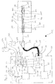
- Figure 3 shows an arrangement 301 with a supply device 330 and a Ablationskatheter, which via a socket 332 with the supply unit 330th connected is.
- the ablation catheter includes a catheter shaft 306 which fits into a handle 336, wherein the handle 336 connected to a flexible tube 333 is.
- a plug 331 is attached at the end, which with the socket 332 is connectable.
- the distal end of the catheter shaft 306 is shown in FIG Magnification window 302 shown.
- the catheter shaft 306 has a Shaft wall 303 having a first lumen 309 and a second lumen 307 encloses.
- the first lumen 309 and the second lumen 307 are through a Partition 311 separated from each other.
- the arrangement of the shaft wall 303, the first lumen 309, second lumen 307 and partition 311 is analogous executed in the cross section shown in Figure 1b.
- the first lumen 309, the second lumen 307 and the partition wall 311 are from the distal end of the Catheter shaft 306 to the proximal end of the catheter shaft 306 educated.
- the catheter shaft has a control wire 328, which on distal end of the catheter shaft is attached and along the Catheter longitudinal axis in the first lumen 309 leads into the handle 336, wherein in the handle, the control wire 328 is connected to the slider 337.
- One Actuation of the slider 337 causes a curvature of the distal end of the Catheter with a directional component orthogonal to the catheter longitudinal axis.
- an ablation electrode 305 At the outer distal end of the catheter shaft is an ablation electrode 305 appropriate.
- the ablation electrode is designed as a bipolar electrode and includes a counter electrode 304, which serves as a ring electrode at the distal end the catheter shaft is formed.
- the catheter shaft has a Electrode temperature sensor 322, which at the high-frequency electrode 305th is attached and connected to a temperature sensor line 320, which through the second lumen 307 along the catheter longitudinal axis in the handle 336th empties.
- a wire temperature sensor 325 is in the region of the distal end in the arranged second lumen 307 and is connected to the temperature sensor line 320th connected, which is designed as a two-channel temperature sensor line.
- One Fluid temperature sensor is in the region of the distal end of the catheter in the arranged first lumen and is connected to an electric Fluid temperature sensor line 327, which along the Catheter longitudinal axis is guided in the first lumen and in the handle 336th empties.
- the high-frequency electrode 305 and the counter electrode 304 are provided with a two-channel RF line 324 connected in the second lumen along the electrode line longitudinal axis and into the handle 336th empties.
- the first lumen 309, the fluid temperature sensor line 327 and the Temperature sensor line 320 are in the handle 336 to a trunk group 335 merged, which opens into the plug 331.
- In the socket 332 of Supply unit 330 open a first fluid line 353, a second Fluid line 352, a high-frequency electrical line 368 and a three-channel Temperature sensor line 366. In the case of the coupling of the plug 331 with.
- the first fluid line 353 is fluidly connected to the first lumen 309, the second fluid line 352 fluidly connected to the second lumen 307, the high-frequency electrical line 368 to the high-frequency line 324 electrically connected and the three-channel temperature sensor line 366 with the Fluid temperature sensor line 327 and the temperature sensor line 320 electrically connected.
- the supply device 330 comprises a fluid supply unit 344 which has a Circulation pump 374, which on fluid lines 355 and 354 connected.
- the supply device 330 also has a controllable Cooling unit 342 with a control input on which a thermostat for Having adhered to a predetermined fluid temperature.
- the cooling unit 342 is on the fluid lines 354, 355, 352 and 353 are connected, the fluid line 355 is fluidly connected to the second fluid line 352 via the cooling unit 342, and the Fluid line 354 via the cooling unit 342 with the first fluid line 353rd fluidly connected.
- the cooling unit 342 is preferably a Peltier cooling unit formed and includes at least one Peltier element.
- the arrangement 301 also includes a fluid supply reservoir 358 which communicates via a fluid supply line 356 is connected to the fluid supply unit 344 and there via a in the Fluid supply unit included inlet valve 378 with the pump inlet 377th is connected, to which also the fluid line 354 is connected.
- the Arrangement 301 also includes a fluid discharge container 359, in which a Fluid discharge line 357 opens, which via a in the fluid supply unit 344 contained pressure relief valve 376 with the circulation pump outlet 375 in the case the opening of the pressure relief valve 376 is fluidly connected. Of the Circulation pump outlet 375 is connected to fluid line 355.
- the Valves 376 and 378 and the pump 374 are controllable.
- the fluid supply unit 344 has a control input and is connected via a control line 360 with the control output of a temperature control and control unit 346th connected.
- the fluid supply unit 344 is formed due to the Control information of a control signal received via the control line 360 optionally to adjust the pumping volume of the circulation pump 374 or the To open or close valves 378 and 376.
- the temperature control and Control unit 346 has an output side via an electrical connection line 362 for controlling the cooling unit 342 connected to the control input.
- the Cooling unit 342 is formed due to a signal received via the control line Control signal to cool a flowing through the cooling unit 342 fluid.
- the Cooling unit 342 can also be designed to correspond to the control signal Adjust cooling capacity or fluid temperature.
- the cooling unit 342 a Include temperature controller.
- the temperature control and control unit is via a three-channel temperature sensor line 366 with those contained in the catheter shaft Temperature sensors 325, 326 and 322 operatively connected.
- the fluid temperature sensor 326 may alternatively be arranged in the first lumen 309 of the catheter shaft 306 may also be arranged in the handle 336 and is also located there in the first lumen 309 or with the first lumen 309 connected thermally conductive.
- the supply device 330 also includes a high frequency generator 340, which via a high-frequency electrical line 368 and an electrical High frequency line 324 with the high frequency electrode 305 and the Counter electrode 304 is connected.
- the electrical high frequency lines 368 and 324 are formed to two channels.
- the high frequency generator 340 is via a high frequency control line 364 with the temperature control and Control unit 346 connected.
- the temperature control and control unit 346 is via a bidirectional data bus 381 to an input unit 380 connected, wherein the input unit via a connecting line 383 with a display 382 is connected.
- the input unit 380 which includes, for example, a keypad, can Operating parameters for operating the ablation catheter in the Temperaturkontrollund Control unit 346 are entered. These are, for example, the inputs and Turning off a high frequency power or preselecting a predetermined one High frequency power, which delivered via the high-frequency electrode 305 or preselecting a desired ablation electrode temperature.
- the temperature control and control unit 346 which for example a Microprocessor is formed, according to the specification by the Input unit 380 a signal corresponding to the input value for generation a high frequency power corresponding to the input value over the Radio frequency control line 364 to the high frequency generator 340 to send.
- High-frequency generator 340 is formed due to the over High frequency control line 364 received control signal a the Input value corresponding high frequency power over the electrical RF line 368 and the operatively connected thereto High-frequency electrode 305 deliver.
- the temperature sensors 325, 326 and 322 are formed, a temperature signal representing the detected temperature to create.
- the generated by the temperature sensors respectively Temperature signals are available via the respective temperature sensors connected temperature sensor lines 327 and 320, as well as the three-channel Temperature sensor line 366 of the temperature control and control unit 346 for Available.
- the temperature control and control unit 346 is formed over the three-channel temperature sensor line 366 received temperature signals to evaluate, and the pumping volume of the circulation pump 374 via the Connecting line 360, the cooling capacity of the cooling unit 342 via the Connecting line 362 and the high-frequency power over the High frequency control line 364 according to one in the temperature control and Control unit 346 predetermined control algorithm to control and generate corresponding control signals.
- the temperature control and Control unit 346 may receive signals corresponding to status information via the send bidirectional data bus 381, the input unit 380 and the Send connection line 383 to the display 382, which is this Can display status information.
- the status information can be, for example the temperature of the high frequency electrode 305 received from the fluid temperature sensor 326 detected fluid temperature of the fluid 370, which is in the first lumen 309, as well as that detected by the wire temperature sensor 325 Fluid temperature of the fluid 370, which is located in the second lumen 307 be.
- the temperature control and control unit 346 is also designed to over evaluate the connection line 366 received signal of a fluid sensor, which is mounted in the fluid supply unit and the fluid filling state and / or the fluid pressure in that formed by the fluid conduits and the lumens To monitor fluid circuit and the inlet valve 378 for admitting a Fluid 370 via the fluid supply line 365 in the fluid circuit according to Taxes.
- the pressure relief valve 376 is formed at a to open predetermined overpressure and thus excess fluid 372 over the Dispense fluid discharge line 357 in the fluid discharge tank 359.
Landscapes
- Health & Medical Sciences (AREA)
- Life Sciences & Earth Sciences (AREA)
- Surgery (AREA)
- Engineering & Computer Science (AREA)
- Plasma & Fusion (AREA)
- Medical Informatics (AREA)
- Otolaryngology (AREA)
- Physics & Mathematics (AREA)
- Cardiology (AREA)
- Biomedical Technology (AREA)
- Heart & Thoracic Surgery (AREA)
- Nuclear Medicine, Radiotherapy & Molecular Imaging (AREA)
- Molecular Biology (AREA)
- Animal Behavior & Ethology (AREA)
- General Health & Medical Sciences (AREA)
- Public Health (AREA)
- Veterinary Medicine (AREA)
- Surgical Instruments (AREA)
- Media Introduction/Drainage Providing Device (AREA)
Abstract
Description
- Fig. 1
- zeigt schematisch dargestellte Querschnitte möglicher Ausführungsformen eines Katheters.
- Fig. 2
- zeigt schematisch Darstellungen zweier Längsschnitte distaler Enden von Ablationskathetern.
- Fig. 3
- zeigt - schematisch dargestellt - ein Ausführungsbeispiel einer Anordnung mit einem Ablationskatheter mit gekühlten Drähten.
Claims (18)
- Katheter zur intravaskulären Applikation, mit einem proximalen und einem distalen Ende und einer Katheterlängsachse, mit
einem sich entlang der Katheterlängsachse von dem proximalen bis zu dem distalen Ende erstreckenden Schaft mit einer fluiddichten Schaftwand
und mindestens einem Lumen, welches ausgebildet ist, ein Fluid zu führen und sich vom proximalen bis zumindest in die Nähe des distalen Endes des Katheters erstreckt und von dem Schaft umschlossen ist,
mindestens einem elektrisch leitfähigen Draht, welcher sich vom proximalen bis zumindest in die Nähe des distalen Endes des Katheters entlang der Katheterlängsachse erstreckt,
dadurch gekennzeichnet, dass
auf mindestens einer zum Einführen in einen Körper vorgesehenen Abschnittslänge des Katheters,
zwischen einem in dem Lumen befindlichen Fluid und dem elektrisch leitfähigen Draht ein geringerer Wärmeübergangswiderstand herrscht, als zwischen dem Draht und der Schaftwand, so dass in dem Draht entstehende Wärme an das im Lumen fließende Fluid wirksam abgeführt werden kann,
wobei der Katheter mindestens einen Temperatursensor umfasst, welcher angeordnet ist, eine Temperatur zu erfassen, welche im Falle einer Erwärmung des Drahtes zumindest überwiegend von der Erwärmung des Drahtes abhängt. - Katheter nach Anspruch 1, dadurch gekennzeichnet, dass der Katheter ein erstes und ein zweites Lumen aufweist, welche ausgebildet sind, ein Fluid zu führen, sich von dem proximalen bis in die Nähe des distalen Endes des Katheters erstrecken und von dem Schaft umschlossen sind.und der Katheter im Bereich des distalen Endes eine Fluidpassage zwischen dem ersten Lumen und dem zweiten Lumen aufweist, so dass Fluid in einem Lumen in Richtung distales Ende strömen kann und von dort in die Fluidpassage und das zweite Lumen zurück zum proximalen Ende.
- Katheter nach einem der vorhergehenden Ansprüche, dadurch gekennzeichnet, dass der Katheter in der Nähe des distalen Endes wenigstens eine Öffnung aufweist, welche mit wenigstens einem der Lumina fluidverbunden ist und welche derart gestaltet ist, dass Fluid aus dem Katheter nach aussen strömen kann.
- Katheter nach einem der vorhergehenden Ansprüche, dadurch gekennzeichnet, dass der Katheterschaft drei Lumina aufweist, welche jeweils ausgebildet sind, ein Fluid zu führen, und von denen ein Lumen als drahtführendes Lumen ausgebildet ist, in dem wenigstens ein zu kühlender Draht angeordnet ist.
- Katheter nach einem der vorhergehenden Ansprüche, dadurch gekennzeichnet, dass der Katheter wenigstens einen Temperatursensor zur Erfassung der Temperatur des Fluides oder des Drahtes oder der Schaftwand aufweist.
- Katheter nach einem der vorhergehenden Ansprüche, dadurch gekennzeichnet, dass der Draht eine elektrische Zuleitung ist.
- Katheter nach einem der vorhergehenden Ansprüche, dadurch gekennzeichnet, dass der Draht ein Steuerdraht ist, welcher in dem inneren Lumen in Richtung der Katheterlängsachse verschieblich angeordnet ist.
- Katheter nach einem der vorhergehenden Ansprüche, dadurch gekennzeichnet, dass der Katheter entlang der Katheterlängsachse mehrere Temperatursensoren aufweist, welche derart angeordnet sind, die Temperatur eines Drahtes und/oder der Schaftwand und/oder eines Lumens zu erfassen.
- Katheter nach einem der vorhergehenden Ansprüche, dadurch gekennzeichnet, dass der Katheter ein Ablationskatheter ist.
- Katheter nach Anspruch 9 mit einer Ablationselektrode und drei Lumina, dadurch gekennzeichnet, dass in einem ersten Lumen wenigstens ein zu kühlender Draht angeordnet ist und das distale Ende ausgebildet ist, ausschließlich ein in einem zweiten Lumen strömendes Fluid der Ablationselektrode zur Kühlung zuzuführen und ein in dem ersten Lumen zum distalen Ende strömendes Fluid in dem dritten Lumen in Richtung proximales Ende zurückzuführen.
- Katheter nach einem der vorhergehenden . Ansprüche, dadurch gekennzeichnet, dass der Katheter ein Führungsdraht ist.
- Katheter nach einem der vorhergehenden Ansprüche, dadurch gekennzeichnet, dass der Katheter ein Mappingkatheter ist.
- Katheter nach einem der vorhergehenden Ansprüche, dadurch gekennzeichnet, dass der Katheter eine Schrittmacher- oder Defibrillatorelektrode ist.
- Katheter nach einem der vorhergehenden Ansprüche, dadurch gekennzeichnet, dass der Katheter wenigstens einen Temperatursensor aufweist, welcher entlang der Katheterlängsachse im Bereich des zur intrakorporalen Invasion vorgesehenen Abschnittes des Katheterschaftes entfernt von gegebenenfalls vorgesehenen Ablationselektroden angeordnet ist.
- Anordnung zur intravaskulären Invasion, umfassend einen Katheter nach einem der vorhergehenden Ansprüche und
eine Fluidzufuhreinheit, welche mit wenigstens einem Lumen des Katheters fluidverbunden und ausgebildet ist, einen Fluidstrom in das Lumen zu erzeugen. - Anordnung nach Anspruch 15, dadurch gekennzeichnet, dass die Fluidzufuhreinheit eine steuerbare Pumpeinheit enthält, welche wenigstens mit einem Lumen des Katheters fluidverbunden und ausgebildet ist, in Abhängigkeit von einem Fluidsteuersignal ein Fluid in das Lumen zu pumpen.
- Anordnung nach einem der Ansprüche 15 oder 16, dadurch gekennzeichnet, dass die Anordnung eine Kühleinheit umfasst, welche mit wenigstens einem Lumen des Katheters fluidverbunden ist und die Kühleinheit ausgebildet ist, in Abhängigkeit von einem Kühlsteuersignal einem Fluid Wärme zu entziehen.
- Anordnung nach Anspruch 16 oder 17, dadurch gekennzeichnet, dass die Anordnung eine Temperaturkontrolleinheit aufweist, die mit wenigstens einem Temperatursensor, der Pumpeinheit oder der Kühleinheit oder beiden wirkverbunden ist, wobei der Temperatursensor ausgebildet ist, ein eine Temperatur repräsentierendes Temperatursignal zu erzeugen und die Temperaturkontrolleinheit ausgebildet ist, ein von dem Temperatursensor erzeugtes Temperatursignal auszuwerten, und die Pumpeinheit oder die Kühleinheit oder beide gemäß einem in der Temperaturkontrolleinheit vorgegebenen Regelalgorithmus zu steuern und dazu entsprechende Steuersignale zu erzeugen.
Applications Claiming Priority (2)
| Application Number | Priority Date | Filing Date | Title |
|---|---|---|---|
| DE10342709 | 2003-09-11 | ||
| DE10342709A DE10342709A1 (de) | 2003-09-11 | 2003-09-11 | Katheter |
Publications (2)
| Publication Number | Publication Date |
|---|---|
| EP1514523A1 true EP1514523A1 (de) | 2005-03-16 |
| EP1514523B1 EP1514523B1 (de) | 2013-03-27 |
Family
ID=34129818
Family Applications (1)
| Application Number | Title | Priority Date | Filing Date |
|---|---|---|---|
| EP04090313A Expired - Lifetime EP1514523B1 (de) | 2003-09-11 | 2004-08-13 | Katheter |
Country Status (3)
| Country | Link |
|---|---|
| US (1) | US7507237B2 (de) |
| EP (1) | EP1514523B1 (de) |
| DE (1) | DE10342709A1 (de) |
Cited By (2)
| Publication number | Priority date | Publication date | Assignee | Title |
|---|---|---|---|---|
| WO2009048943A1 (en) * | 2007-10-09 | 2009-04-16 | Boston Scientific Scimed, Inc. | Cooled ablation catheter devices and methods of use |
| CN113288403A (zh) * | 2015-05-18 | 2021-08-24 | 韦伯斯特生物官能(以色列)有限公司 | 具有共轴热电偶的导管 |
Families Citing this family (16)
| Publication number | Priority date | Publication date | Assignee | Title |
|---|---|---|---|---|
| PL1639956T3 (pl) * | 2004-09-27 | 2007-11-30 | Vibratech Ab | Układ do leczenia guzów |
| DE102005023303A1 (de) * | 2005-05-13 | 2006-11-16 | Celon Ag Medical Instruments | Biegeweiche Applikationsvorrichtung zur Hochfrequenztherapie von biologischem Gewebe |
| US8852184B2 (en) * | 2005-09-15 | 2014-10-07 | Cannuflow, Inc. | Arthroscopic surgical temperature control system |
| WO2008045925A2 (en) * | 2006-10-10 | 2008-04-17 | St. Jude Medical, Atrial Fibrillation Division, Inc. | Ablation electrode assembly with insulated distal outlet |
| KR20170081278A (ko) | 2008-09-11 | 2017-07-11 | 어시스트 메디칼 시스템즈, 인크. | 생리학적 센서 공급 장치 및 방법 |
| WO2010093603A1 (en) | 2009-02-11 | 2010-08-19 | Boston Scientific Scimed, Inc. | Insulated ablation catheter devices and methods of use |
| EP2380517A1 (de) | 2010-04-20 | 2011-10-26 | VascoMed GmbH | Elektrode für einen elektrophysiologischen Ablationskatheter |
| US9259161B2 (en) | 2011-05-11 | 2016-02-16 | Acist Medical Systems, Inc. | Intravascular sensing method and system |
| US10244951B2 (en) | 2014-06-10 | 2019-04-02 | Acist Medical Systems, Inc. | Physiological sensor delivery device and method |
| EP3206612B1 (de) | 2014-10-13 | 2022-06-29 | Boston Scientific Scimed Inc. | Gewebe diagnose und behandlung mittels mini-elektroden |
| WO2018227268A1 (en) * | 2017-06-12 | 2018-12-20 | Kardium Inc. | Medical device systems and methods for activating transducers based on delivery shaft member temperature |
| US11284939B2 (en) | 2017-07-06 | 2022-03-29 | Biosense Webster (Israel) Ltd. | Irrigated catheter with improved ablation tip electrode fluid distribution |
| EP3709915A1 (de) * | 2017-11-13 | 2020-09-23 | Biocompatibles UK Limited | Kryoablationssystem mit magnetresonanzbildgebungsdetektion |
| CN111954487B (zh) | 2018-04-20 | 2024-06-18 | 阿西斯特医药系统公司 | 血管的评估 |
| EP3852600A4 (de) * | 2018-09-21 | 2022-06-15 | Saphena Medical, Inc. | Chirurgische insufflations- und irrigationsleitungen und verfahren zur verwendung |
| US12434017B2 (en) | 2019-05-01 | 2025-10-07 | Saphena Medical, Inc. | Surgical insufflation systems and methods for use |
Citations (6)
| Publication number | Priority date | Publication date | Assignee | Title |
|---|---|---|---|---|
| US5281215A (en) * | 1992-04-16 | 1994-01-25 | Implemed, Inc. | Cryogenic catheter |
| US5348554A (en) | 1992-12-01 | 1994-09-20 | Cardiac Pathways Corporation | Catheter for RF ablation with cooled electrode |
| US5755760A (en) | 1996-03-11 | 1998-05-26 | Medtronic, Inc. | Deflectable catheter |
| US5980515A (en) | 1997-12-19 | 1999-11-09 | Irvine Biomedical, Inc. | Devices and methods for lead extraction |
| EP1008327A2 (de) | 1998-12-03 | 2000-06-14 | Cordis Webster, Inc. | Elektroden-Katheter mit geteilter und gespülter Spitze |
| US20030004506A1 (en) | 2001-06-28 | 2003-01-02 | Scimed Life Systems, Inc. | Catheter with an irrigated composite tip electrode |
Family Cites Families (6)
| Publication number | Priority date | Publication date | Assignee | Title |
|---|---|---|---|---|
| US4506A (en) * | 1846-05-09 | Dentist s turw-key | ||
| DE69233091T2 (de) * | 1991-11-08 | 2004-05-06 | Boston Scientific Ltd., St. Michael | Ablationselektrode mit isoliertem temperaturmesselement |
| US5540681A (en) * | 1992-04-10 | 1996-07-30 | Medtronic Cardiorhythm | Method and system for radiofrequency ablation of tissue |
| US6620188B1 (en) * | 1998-08-24 | 2003-09-16 | Radiant Medical, Inc. | Methods and apparatus for regional and whole body temperature modification |
| CA2164860C (en) * | 1993-06-10 | 2005-09-06 | Mir A. Imran | Transurethral radio frequency ablation apparatus |
| JP3835703B2 (ja) * | 1995-05-01 | 2006-10-18 | ボストン サイエンティフィック リミテッド | 能動的に冷却される電極を備えたアブレーション中の身体組織の表面下温度を感知するシステム |
-
2003
- 2003-09-11 DE DE10342709A patent/DE10342709A1/de not_active Withdrawn
-
2004
- 2004-08-13 EP EP04090313A patent/EP1514523B1/de not_active Expired - Lifetime
- 2004-09-10 US US10/939,089 patent/US7507237B2/en not_active Expired - Fee Related
Patent Citations (7)
| Publication number | Priority date | Publication date | Assignee | Title |
|---|---|---|---|---|
| US5281215A (en) * | 1992-04-16 | 1994-01-25 | Implemed, Inc. | Cryogenic catheter |
| DE69332414T2 (de) | 1992-04-16 | 2003-06-12 | Cryocath Technologies Inc., Kirkland | Kryogener katheter |
| US5348554A (en) | 1992-12-01 | 1994-09-20 | Cardiac Pathways Corporation | Catheter for RF ablation with cooled electrode |
| US5755760A (en) | 1996-03-11 | 1998-05-26 | Medtronic, Inc. | Deflectable catheter |
| US5980515A (en) | 1997-12-19 | 1999-11-09 | Irvine Biomedical, Inc. | Devices and methods for lead extraction |
| EP1008327A2 (de) | 1998-12-03 | 2000-06-14 | Cordis Webster, Inc. | Elektroden-Katheter mit geteilter und gespülter Spitze |
| US20030004506A1 (en) | 2001-06-28 | 2003-01-02 | Scimed Life Systems, Inc. | Catheter with an irrigated composite tip electrode |
Cited By (5)
| Publication number | Priority date | Publication date | Assignee | Title |
|---|---|---|---|---|
| WO2009048943A1 (en) * | 2007-10-09 | 2009-04-16 | Boston Scientific Scimed, Inc. | Cooled ablation catheter devices and methods of use |
| US9023030B2 (en) | 2007-10-09 | 2015-05-05 | Boston Scientific Scimed, Inc. | Cooled ablation catheter devices and methods of use |
| US10813687B2 (en) | 2007-10-09 | 2020-10-27 | Boston Scientific Scimed Inc | Cooled ablation catheter devices and methods of use |
| CN113288403A (zh) * | 2015-05-18 | 2021-08-24 | 韦伯斯特生物官能(以色列)有限公司 | 具有共轴热电偶的导管 |
| CN113288403B (zh) * | 2015-05-18 | 2024-04-16 | 韦伯斯特生物官能(以色列)有限公司 | 具有共轴热电偶的导管 |
Also Published As
| Publication number | Publication date |
|---|---|
| US20050065511A1 (en) | 2005-03-24 |
| DE10342709A1 (de) | 2005-04-21 |
| US7507237B2 (en) | 2009-03-24 |
| EP1514523B1 (de) | 2013-03-27 |
Similar Documents
| Publication | Publication Date | Title |
|---|---|---|
| EP1514523B1 (de) | Katheter | |
| DE69432671T2 (de) | Flüssigkeitsgekühlte und perfundierte spitze eines katheters | |
| KR101379647B1 (ko) | 난류를 갖는 개방 관주식 절제 카테터 | |
| EP1044654B1 (de) | Anordnung zur elektro-thermischen Behandlung des menschlichen oder tierischen Körpers | |
| DE69813919T2 (de) | Flüssigkeitgekülter Ablationskatheter und Herstellungsmethode | |
| US6458123B1 (en) | Ablation catheter with positional sensor | |
| US6063080A (en) | Linear catheter ablation system | |
| DE69423295T2 (de) | Katheter zur Kryo-Abtragung | |
| DE69530493T2 (de) | Ablationsgerät | |
| DE112015001054B4 (de) | Gespülter Ablationskatheter | |
| DE19739699A1 (de) | Elektrodenanordnung zur elektro-thermischen Behandlung des menschlichen oder tierischen Körpers | |
| EP2335632B1 (de) | Katheter mit spiralförmiger Elektrode | |
| DE60114486T2 (de) | Kryoablationskatheter mit ausdehnbarer Kühlkammer | |
| DE69330821T2 (de) | Katheter zur Radio-Frequenz Ablation mit abkühlender Elektrode | |
| DE69728167T2 (de) | Ablationskatheter zur behandlung von tumoren | |
| JP6419779B2 (ja) | アブレーションカテーテル | |
| WO2001089403A1 (de) | Elektrodenanordnung für ein chirurgisches instrument | |
| US9579148B2 (en) | Irrigated ablation electrode having recessed surface portions | |
| EP0714635B1 (de) | Hochfrequenztherapieeinrichtung zur interstitiellen Thermotherapie von Tumoren | |
| EP2774567A1 (de) | Bewässerter Ablationskatheter mit Bewässerungsanschlüssen mit reduziertem hydraulischen Widerstand | |
| US9107673B2 (en) | Irrigation catheter | |
| EP3788974A1 (de) | Ablationssonde | |
| DE69432361T2 (de) | Katheter für verschiedene in-situ gewebetherapien | |
| US9694160B2 (en) | Deflectable catheter constructed to inhibit component migration | |
| DE202010016945U1 (de) | Transthorakaler AFIB Herz-Katheter |
Legal Events
| Date | Code | Title | Description |
|---|---|---|---|
| PUAI | Public reference made under article 153(3) epc to a published international application that has entered the european phase |
Free format text: ORIGINAL CODE: 0009012 |
|
| AK | Designated contracting states |
Kind code of ref document: A1 Designated state(s): AT BE BG CH CY CZ DE DK EE ES FI FR GB GR HU IE IT LI LU MC NL PL PT RO SE SI SK TR |
|
| AX | Request for extension of the european patent |
Extension state: AL HR LT LV MK |
|
| 17P | Request for examination filed |
Effective date: 20050916 |
|
| AKX | Designation fees paid |
Designated state(s): AT BE BG CH CY CZ DE DK EE ES FI FR GB GR HU IE IT LI LU MC NL PL PT RO SE SI SK TR |
|
| 17Q | First examination report despatched |
Effective date: 20080307 |
|
| RAP1 | Party data changed (applicant data changed or rights of an application transferred) |
Owner name: BIOTRONIK SE & CO. KG |
|
| RAP1 | Party data changed (applicant data changed or rights of an application transferred) |
Owner name: BIOTRONIK SE & CO. KG |
|
| GRAP | Despatch of communication of intention to grant a patent |
Free format text: ORIGINAL CODE: EPIDOSNIGR1 |
|
| GRAS | Grant fee paid |
Free format text: ORIGINAL CODE: EPIDOSNIGR3 |
|
| GRAP | Despatch of communication of intention to grant a patent |
Free format text: ORIGINAL CODE: EPIDOSNIGR1 |
|
| GRAA | (expected) grant |
Free format text: ORIGINAL CODE: 0009210 |
|
| AK | Designated contracting states |
Kind code of ref document: B1 Designated state(s): AT BE BG CH CY CZ DE DK EE ES FI FR GB GR HU IE IT LI LU MC NL PL PT RO SE SI SK TR |
|
| REG | Reference to a national code |
Ref country code: GB Ref legal event code: FG4D Free format text: NOT ENGLISH |
|
| REG | Reference to a national code |
Ref country code: CH Ref legal event code: EP |
|
| REG | Reference to a national code |
Ref country code: AT Ref legal event code: REF Ref document number: 602867 Country of ref document: AT Kind code of ref document: T Effective date: 20130415 |
|
| REG | Reference to a national code |
Ref country code: IE Ref legal event code: FG4D Free format text: LANGUAGE OF EP DOCUMENT: GERMAN |
|
| REG | Reference to a national code |
Ref country code: DE Ref legal event code: R096 Ref document number: 502004014085 Country of ref document: DE Effective date: 20130523 |
|
| PG25 | Lapsed in a contracting state [announced via postgrant information from national office to epo] |
Ref country code: BG Free format text: LAPSE BECAUSE OF FAILURE TO SUBMIT A TRANSLATION OF THE DESCRIPTION OR TO PAY THE FEE WITHIN THE PRESCRIBED TIME-LIMIT Effective date: 20130627 Ref country code: SE Free format text: LAPSE BECAUSE OF FAILURE TO SUBMIT A TRANSLATION OF THE DESCRIPTION OR TO PAY THE FEE WITHIN THE PRESCRIBED TIME-LIMIT Effective date: 20130327 |
|
| PG25 | Lapsed in a contracting state [announced via postgrant information from national office to epo] |
Ref country code: SI Free format text: LAPSE BECAUSE OF FAILURE TO SUBMIT A TRANSLATION OF THE DESCRIPTION OR TO PAY THE FEE WITHIN THE PRESCRIBED TIME-LIMIT Effective date: 20130327 Ref country code: GR Free format text: LAPSE BECAUSE OF FAILURE TO SUBMIT A TRANSLATION OF THE DESCRIPTION OR TO PAY THE FEE WITHIN THE PRESCRIBED TIME-LIMIT Effective date: 20130628 Ref country code: FI Free format text: LAPSE BECAUSE OF FAILURE TO SUBMIT A TRANSLATION OF THE DESCRIPTION OR TO PAY THE FEE WITHIN THE PRESCRIBED TIME-LIMIT Effective date: 20130327 |
|
| REG | Reference to a national code |
Ref country code: NL Ref legal event code: VDEP Effective date: 20130327 |
|
| PG25 | Lapsed in a contracting state [announced via postgrant information from national office to epo] |
Ref country code: SK Free format text: LAPSE BECAUSE OF FAILURE TO SUBMIT A TRANSLATION OF THE DESCRIPTION OR TO PAY THE FEE WITHIN THE PRESCRIBED TIME-LIMIT Effective date: 20130327 Ref country code: ES Free format text: LAPSE BECAUSE OF FAILURE TO SUBMIT A TRANSLATION OF THE DESCRIPTION OR TO PAY THE FEE WITHIN THE PRESCRIBED TIME-LIMIT Effective date: 20130708 Ref country code: NL Free format text: LAPSE BECAUSE OF FAILURE TO SUBMIT A TRANSLATION OF THE DESCRIPTION OR TO PAY THE FEE WITHIN THE PRESCRIBED TIME-LIMIT Effective date: 20130327 Ref country code: RO Free format text: LAPSE BECAUSE OF FAILURE TO SUBMIT A TRANSLATION OF THE DESCRIPTION OR TO PAY THE FEE WITHIN THE PRESCRIBED TIME-LIMIT Effective date: 20130327 Ref country code: CZ Free format text: LAPSE BECAUSE OF FAILURE TO SUBMIT A TRANSLATION OF THE DESCRIPTION OR TO PAY THE FEE WITHIN THE PRESCRIBED TIME-LIMIT Effective date: 20130327 Ref country code: PT Free format text: LAPSE BECAUSE OF FAILURE TO SUBMIT A TRANSLATION OF THE DESCRIPTION OR TO PAY THE FEE WITHIN THE PRESCRIBED TIME-LIMIT Effective date: 20130729 Ref country code: EE Free format text: LAPSE BECAUSE OF FAILURE TO SUBMIT A TRANSLATION OF THE DESCRIPTION OR TO PAY THE FEE WITHIN THE PRESCRIBED TIME-LIMIT Effective date: 20130327 |
|
| PG25 | Lapsed in a contracting state [announced via postgrant information from national office to epo] |
Ref country code: PL Free format text: LAPSE BECAUSE OF FAILURE TO SUBMIT A TRANSLATION OF THE DESCRIPTION OR TO PAY THE FEE WITHIN THE PRESCRIBED TIME-LIMIT Effective date: 20130327 Ref country code: CY Free format text: LAPSE BECAUSE OF FAILURE TO SUBMIT A TRANSLATION OF THE DESCRIPTION OR TO PAY THE FEE WITHIN THE PRESCRIBED TIME-LIMIT Effective date: 20130327 |
|
| PG25 | Lapsed in a contracting state [announced via postgrant information from national office to epo] |
Ref country code: DK Free format text: LAPSE BECAUSE OF FAILURE TO SUBMIT A TRANSLATION OF THE DESCRIPTION OR TO PAY THE FEE WITHIN THE PRESCRIBED TIME-LIMIT Effective date: 20130327 |
|
| PLBE | No opposition filed within time limit |
Free format text: ORIGINAL CODE: 0009261 |
|
| STAA | Information on the status of an ep patent application or granted ep patent |
Free format text: STATUS: NO OPPOSITION FILED WITHIN TIME LIMIT |
|
| BERE | Be: lapsed |
Owner name: BIOTRONIK SE & CO. K.G. Effective date: 20130831 |
|
| PG25 | Lapsed in a contracting state [announced via postgrant information from national office to epo] |
Ref country code: IT Free format text: LAPSE BECAUSE OF FAILURE TO SUBMIT A TRANSLATION OF THE DESCRIPTION OR TO PAY THE FEE WITHIN THE PRESCRIBED TIME-LIMIT Effective date: 20130327 |
|
| 26N | No opposition filed |
Effective date: 20140103 |
|
| REG | Reference to a national code |
Ref country code: DE Ref legal event code: R097 Ref document number: 502004014085 Country of ref document: DE Effective date: 20140103 |
|
| GBPC | Gb: european patent ceased through non-payment of renewal fee |
Effective date: 20130813 |
|
| PG25 | Lapsed in a contracting state [announced via postgrant information from national office to epo] |
Ref country code: MC Free format text: LAPSE BECAUSE OF FAILURE TO SUBMIT A TRANSLATION OF THE DESCRIPTION OR TO PAY THE FEE WITHIN THE PRESCRIBED TIME-LIMIT Effective date: 20130327 |
|
| REG | Reference to a national code |
Ref country code: FR Ref legal event code: ST Effective date: 20140430 |
|
| PG25 | Lapsed in a contracting state [announced via postgrant information from national office to epo] |
Ref country code: BE Free format text: LAPSE BECAUSE OF NON-PAYMENT OF DUE FEES Effective date: 20130831 |
|
| PG25 | Lapsed in a contracting state [announced via postgrant information from national office to epo] |
Ref country code: GB Free format text: LAPSE BECAUSE OF NON-PAYMENT OF DUE FEES Effective date: 20130813 |
|
| PG25 | Lapsed in a contracting state [announced via postgrant information from national office to epo] |
Ref country code: FR Free format text: LAPSE BECAUSE OF NON-PAYMENT OF DUE FEES Effective date: 20130902 |
|
| REG | Reference to a national code |
Ref country code: AT Ref legal event code: MM01 Ref document number: 602867 Country of ref document: AT Kind code of ref document: T Effective date: 20130813 |
|
| PG25 | Lapsed in a contracting state [announced via postgrant information from national office to epo] |
Ref country code: AT Free format text: LAPSE BECAUSE OF NON-PAYMENT OF DUE FEES Effective date: 20130813 |
|
| PG25 | Lapsed in a contracting state [announced via postgrant information from national office to epo] |
Ref country code: TR Free format text: LAPSE BECAUSE OF FAILURE TO SUBMIT A TRANSLATION OF THE DESCRIPTION OR TO PAY THE FEE WITHIN THE PRESCRIBED TIME-LIMIT Effective date: 20130327 |
|
| PG25 | Lapsed in a contracting state [announced via postgrant information from national office to epo] |
Ref country code: HU Free format text: LAPSE BECAUSE OF FAILURE TO SUBMIT A TRANSLATION OF THE DESCRIPTION OR TO PAY THE FEE WITHIN THE PRESCRIBED TIME-LIMIT; INVALID AB INITIO Effective date: 20040813 Ref country code: LU Free format text: LAPSE BECAUSE OF NON-PAYMENT OF DUE FEES Effective date: 20130813 |
|
| PGFP | Annual fee paid to national office [announced via postgrant information from national office to epo] |
Ref country code: DE Payment date: 20160809 Year of fee payment: 13 |
|
| PGFP | Annual fee paid to national office [announced via postgrant information from national office to epo] |
Ref country code: CH Payment date: 20170830 Year of fee payment: 14 |
|
| PGFP | Annual fee paid to national office [announced via postgrant information from national office to epo] |
Ref country code: IE Payment date: 20170822 Year of fee payment: 14 |
|
| REG | Reference to a national code |
Ref country code: DE Ref legal event code: R119 Ref document number: 502004014085 Country of ref document: DE |
|
| PG25 | Lapsed in a contracting state [announced via postgrant information from national office to epo] |
Ref country code: DE Free format text: LAPSE BECAUSE OF NON-PAYMENT OF DUE FEES Effective date: 20180301 |
|
| REG | Reference to a national code |
Ref country code: CH Ref legal event code: PL |
|
| PG25 | Lapsed in a contracting state [announced via postgrant information from national office to epo] |
Ref country code: CH Free format text: LAPSE BECAUSE OF NON-PAYMENT OF DUE FEES Effective date: 20180831 Ref country code: LI Free format text: LAPSE BECAUSE OF NON-PAYMENT OF DUE FEES Effective date: 20180831 |
|
| REG | Reference to a national code |
Ref country code: IE Ref legal event code: MM4A |
|
| PG25 | Lapsed in a contracting state [announced via postgrant information from national office to epo] |
Ref country code: IE Free format text: LAPSE BECAUSE OF NON-PAYMENT OF DUE FEES Effective date: 20180813 |