EP1514501A1 - Automatic food-heating device - Google Patents
Automatic food-heating device Download PDFInfo
- Publication number
- EP1514501A1 EP1514501A1 EP03725224A EP03725224A EP1514501A1 EP 1514501 A1 EP1514501 A1 EP 1514501A1 EP 03725224 A EP03725224 A EP 03725224A EP 03725224 A EP03725224 A EP 03725224A EP 1514501 A1 EP1514501 A1 EP 1514501A1
- Authority
- EP
- European Patent Office
- Prior art keywords
- food
- conveyor belt
- heater
- double conveyor
- container
- Prior art date
- Legal status (The legal status is an assumption and is not a legal conclusion. Google has not performed a legal analysis and makes no representation as to the accuracy of the status listed.)
- Withdrawn
Links
- 238000010438 heat treatment Methods 0.000 title claims abstract description 31
- 235000013305 food Nutrition 0.000 claims abstract description 94
- 238000000034 method Methods 0.000 claims description 10
- 239000000463 material Substances 0.000 claims description 9
- 230000009471 action Effects 0.000 claims description 8
- 230000004044 response Effects 0.000 claims description 8
- 230000003993 interaction Effects 0.000 claims description 3
- 230000001360 synchronised effect Effects 0.000 claims description 3
- 239000004033 plastic Substances 0.000 description 8
- 229920003023 plastic Polymers 0.000 description 8
- 238000004140 cleaning Methods 0.000 description 5
- 230000007246 mechanism Effects 0.000 description 5
- 238000006073 displacement reaction Methods 0.000 description 4
- 239000007788 liquid Substances 0.000 description 4
- 230000008569 process Effects 0.000 description 4
- XEEYBQQBJWHFJM-UHFFFAOYSA-N Iron Chemical compound [Fe] XEEYBQQBJWHFJM-UHFFFAOYSA-N 0.000 description 2
- 239000000696 magnetic material Substances 0.000 description 2
- 230000007547 defect Effects 0.000 description 1
- 230000000694 effects Effects 0.000 description 1
- 230000005484 gravity Effects 0.000 description 1
- 239000003779 heat-resistant material Substances 0.000 description 1
- 229910052742 iron Inorganic materials 0.000 description 1
- 230000004048 modification Effects 0.000 description 1
- 238000012986 modification Methods 0.000 description 1
- 235000013550 pizza Nutrition 0.000 description 1
- 230000000284 resting effect Effects 0.000 description 1
- 238000005507 spraying Methods 0.000 description 1
Images


Classifications
-
- G—PHYSICS
- G07—CHECKING-DEVICES
- G07F—COIN-FREED OR LIKE APPARATUS
- G07F17/00—Coin-freed apparatus for hiring articles; Coin-freed facilities or services
- G07F17/0064—Coin-freed apparatus for hiring articles; Coin-freed facilities or services for processing of food articles
- G07F17/0078—Food articles which need to be processed for dispensing in a hot or cooked condition, e.g. popcorn, nuts
-
- A—HUMAN NECESSITIES
- A47—FURNITURE; DOMESTIC ARTICLES OR APPLIANCES; COFFEE MILLS; SPICE MILLS; SUCTION CLEANERS IN GENERAL
- A47J—KITCHEN EQUIPMENT; COFFEE MILLS; SPICE MILLS; APPARATUS FOR MAKING BEVERAGES
- A47J37/00—Baking; Roasting; Grilling; Frying
- A47J37/04—Roasting apparatus with movably-mounted food supports or with movable heating implements; Spits
- A47J37/044—Roasting apparatus with movably-mounted food supports or with movable heating implements; Spits with conveyors moving in a horizontal or an inclined plane
-
- A—HUMAN NECESSITIES
- A47—FURNITURE; DOMESTIC ARTICLES OR APPLIANCES; COFFEE MILLS; SPICE MILLS; SUCTION CLEANERS IN GENERAL
- A47J—KITCHEN EQUIPMENT; COFFEE MILLS; SPICE MILLS; APPARATUS FOR MAKING BEVERAGES
- A47J37/00—Baking; Roasting; Grilling; Frying
- A47J37/04—Roasting apparatus with movably-mounted food supports or with movable heating implements; Spits
- A47J37/046—Roasting apparatus with movably-mounted food supports or with movable heating implements; Spits with horizontal turntables
-
- G—PHYSICS
- G07—CHECKING-DEVICES
- G07F—COIN-FREED OR LIKE APPARATUS
- G07F9/00—Details other than those peculiar to special kinds or types of apparatus
- G07F9/10—Casings or parts thereof, e.g. with means for heating or cooling
- G07F9/105—Heating or cooling means, for temperature and humidity control, for the conditioning of articles and their storage
Definitions
- This invention is related to the field of automisation, and more specifically to the processes of supply, dispatch, dispensing and/or sale of products.
- the known technical solutions describe a device for the sale of products, including food, with a body wherein there is a store of food products with individual containers, a food heater, a window for the delivery of food and a transport system for the individual conveyance of food containers from the store to the heater and from the heater to the delivery window.
- Automatic food-heating device comprising a body which houses a store for food with individual containers, a food heater, a window for delivery of food and a transport system for the individual conveyance of food containers from the store to the heater and from the heater to the delivery window, the heater has a rotating support for the food container, the transport system contains a double conveyor belt (or double chain, or double cord), whose individual belts (or chains, or cords) are synchronised and arranged in parallel at a distance less than the minimum horizontal size of the container, but greater than the horizontal size of the rotating support for food in the heater, the individual conveyor belts are arranged symmetrically in relation to the axis of rotation of the rotating support, the double conveyor belt can move in the vertical direction, being limited in its upper part in such a way that the lower part of the container placed on the double conveyor belt is located higher than the upper part of the rotating support for food, and limited in its lower part in such a way that the container rests on the rotating support and does not touch the conveyor belt.
- the transport system contains a
- the objective of the invention is to expand the functional possibilities of the device by means of rotating the food during the heating. This will enable a more uniform heating of the food to be obtained and therefore to improve its consumption qualities.
- Automatic food-heating device comprising a body which houses a store for food with individual containers, a food heater, a window for delivery of food and a transport system for the individual conveyance of food containers from the store to the heater and from the heater to the delivery window, the heater has a rotating support for the food container, the transport system contains a double conveyor belt (or double chain, or double cord), whose individual belts (or chains, or cords whose cross-section can be circular, rectangular or elliptical) are synchronised and arranged in parallel at a distance less than the minimum horizontal size of the container, but greater than the horizontal size of the rotating support for food in the heater, the individual conveyor belts are arranged symmetrically in relation to the axis of rotation of the rotating support, the double conveyor belt can move in the vertical direction, being limited in its upper part in such a way that the lower part of the container placed on the double conveyor belt is located higher than the upper part of the rotating support for food, and limited in its lower part in such a way that the container rests on the rotating support
- the double conveyor belt can rotate around a horizontal axis, located outside the heater and orientated perpendicularly to the movement of the belt.
- the conveyor belt has a spring and a limit element, and it can be highlighted that in the absence of exterior actions the double conveyor belt rotates around the horizontal axis until the limit element, due to the influence of the spring.
- At least one of the individual belts of the conveyor belt includes a projection with the possibility of interaction with the response part, located in the base.
- the heater has a hatch located with the possibility of moving in the vertical direction and interacting with the double conveyor belt; the closed position of the hatch corresponds to the lowest position of the double conveyor belt.
- the transport system contains a device for carrying out the perforation of the wrapping material for the food.
- the method of control of the automatic heating device consists of the food being conserved in the store and being conveyed by the conveyor belt to the heater, being heated and, with the help of the double conveyor belt, being transported to the delivery window following the transfer of the food container to the heater, the conveyor belt is lowered to the point at which the container comes into contact with the rotating support and ceases to interact with the double conveyor belt, the rotation of the food container is done with the help of the rotating support during the heating, at the end of the heating the food container stops rotating and the double conveyor belt is then raised up to the upper position until the food container rests on the double conveyor belt and the food container does not touch the rotating support, the food container is then conveyed to the delivery window.
- the wrapping material for the food is perforated at one or several points.
- Such an execution permits the functional possibilities of the apparatus to be expanded by means of rotating the food during its heating, which is especially important when using microwaves for heating. With such an execution of the device, a more uniform heating of the food is achieved, which improves its consumption qualities. In comparison with other possible technical solutions related to the operation of loading-offloading of the heater with the help of a special robot, the technical solution that is proposed becomes considerably more simple and cheap.
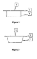
- the food store is full of individually wrapped food, for example, portions of pizza, located on individual semi-rigid (or rigid) trays of a plastic material or material of special composition with a cylindrical, conical or rectangular shape 1.
- a widened part 2 In the upper part of the trays there exists a widened part 2, sealed above and with a cover of plastic or special fine material 3.
- the tray 1 with the food is expelled from the store with the help of the usual methods (for example, with a screw thruster or spiral thruster, etc.), and the tray 1 is then conveyed with the help of the usual methods (for example, inclined grooves which permit the displacement of the object with the action of the force of gravity, or a special additional chain, etc.) to the double conveyor belt in such a way that the widened part 2 of the tray 1 at the same time rests on the two belts of the chain 4.
- Those belts 4 are supported on the support 5 which has an opening with an inlet and an outlet 6, symmetrically arranged with respect to the belts of the double conveyor belt and which has a size greater than the diameter of the tray 1.
- the tray 1 is conveyed in the direction towards the food heater 9 (for example, the microwave).
- the conveyance of the tray 1 ends at the moment in which its position corresponds to the position of the rotary support 10 (the corresponding position is understood as being the position of the tray 1 such that ensures the possibility of locating the tray 1 on the rotating support 10 so that the centre of the tray 1 coincides with the centre of the rotating support when that part of the double conveyor belt that is within the food heater is lowered). After that, the part of the double conveyor belt that is within the food heater is lowered.
- This movement can be done in different ways.
- the chain is fixed in vertical guides with the possibility of vertical translation movement of the entire double conveyor belt, for example, with the help of a special actuator.
- Another possibility is for the double conveyor belt to be fixed in the horizontal axis with the possibility of rotary movement; when that end of the double conveyor belt located in the food heater is lowered, the other end of the double conveyor belt rises up.
- the third possibility is for the double conveyor belt to be fixed with the help of a parallelogram mechanism; in this case the mechanism is progressively displaced via the arc of the circumference.
- the tray 1 comes into contact with the rotating support 10.
- the double conveyor belt ceases to be lowered at the moment in which sufficient space is generated between the widened part 2 of the tray 1 and the individual belts of the double conveyor belt 4, so that, during the rotation of the tray 1, its widened part does not come into contact with the individual belts of the double conveyor belt.
- the hatch of the food heater can be made in the form of two parts: the mobile part 11 and the immobile part 12, securely joined to the body of the food heater.
- the immobile part 12 can be used as support, which limits the vertical movement of the double conveyor belt.
- the mobile part 11 of the hatch can be fixed in vertical directrices with the possibility of vertical movement or it can be fitted with a horizontal rotating shaft.
- the opening and closing of the hatch is done with the help of a special actuator.
- the mobile part 11 of the hatch is closed before the food heater is switched on.
- the actuator of the rotary support 10 is switched on (the actuator itself is located outside the heating zone and is cinematically connected to the rotary support), and when the food heater is switched off so too is the actuator of the rotary support 10.
- the disconnection of the heater is done either with the help of a timer or by means of a temperature sensor signal, when a pre-set temperature is reached in the food heater.
- the mobile part 11 of the hatch for the food heater opens and the double conveyor belt is raised up to the initial position (for example, that defined with a special support). In this position, the tray 1 ceases to make contact with the rotary support 10.
- the motor 7 starts up and the tray 1 with the heated food is moved with the help of the belts of the double conveyor belt 4 from the heater to the position wherein the double conveyor belt was in at the initial moment. Another termination of the process is also possible, but this requires a certain modification to the device.
- the shaft 8 of the double conveyor belt fitted with a motor can be combined, and not cylindrical.
- a turning whose width (size A) corresponds to the distance between the two belts of the double conveyor belt, and the depth of the turning (size B) exceeds the height of the base of the tray 1 at the widened part 2 of the tray.
- the tray 1 does not necessarily need to stop in the position at which it is found in the initial instant.
- the continuation of the movement of the belts of the double conveyor belt is going to cause the tray to move until the far end of the chain and enter into a special container for prepared foods (for example, created in the form of an inclined plane with a horizontal table at one end). In this case, there is no need to use a special device for eliminating the trays from the double conveyor belt.
- the apparatus can be complemented with a special device for the perforation of the covers of the tray made of plastic or special material.
- This device is intended to break the seal of the wrapping for the food before the food is subjected to heating (for example, in the initial position of the tray in the double conveyor belt).
- the device contains an electromagnet 13 with one or several moving needles 14 fixed above the double conveyor belt.
- the needles contain plates 15 (made of a magnetic material, such as iron) and springs 16. In the initial position of the device, the electromagnet 13 is off, and all the needles 14 are raised by virtue of the action of the springs 16.
- the electromagnet comes on for a short time, the plates 15 (under the action of the electromagnet) are attracted to it, thereby ensuring the downwards movement of the needles 14. With this movement, the needles 14 perforate the cover of the tray. Once the electromagnet has been disconnected, the needles return to their initial position under the action of the springs.
- the device can be completed with a device for cleaning the needles.
- the device for cleaning the needles can be made in the form of a container with sprayers for the supply and spraying of the cleaning liquid at high pressure from a special pump, sprayers for the supply of compressed air and a tube for diverting the liquid and air away from the container.
- the device for perforating the plastic covers is mobile (for example, fixed in directrices permitting horizontal and vertical movement, and provided with the corresponding actuators).
- the device is displaced to the container in such a way that the magnet remains pressing against the upper part of the container and the needles are located within the container.
- the sprayers with the cleaning liquid are turned on and the liquid cleans the needles.
- the sprayers containing air are turned on in order to dry the needles.
- the air supply is then disconnected and the device for perforation of the covers is displaced to the initial position in order to allow the needles to perforate the cover of the new tray.
- the oven When using the oven as a food heater, all the elements to be found inside the oven (the belts of the double conveyor belt, the motorless shaft of the double conveyor belt, the support for the belts of the double conveyor belt, the rotary support) must be made of heat resistant materials. Due to using microwaves, all these elements must be made of materials that do not heat up under the action of microwave irradiation, for example, be made of plastics of special composition which have sufficient resistance to heat for interacting with the hot tray.
- the double conveyor belt can be fitted with a special spring 17, adjusted in such a way that the double conveyor belt together with the tray on top of it occupies the extreme upward position (for example, defined by a special support). In this case, for the vertical displacement there is no need to have a special actuator in order to perform this movement. It can be carried out with the help of the actuator for the mobile hatch 11 of the food heater or with the help of the motor 7 of the double conveyor belt (in this latter case, at least one belt of the double conveyor belt must contain a special projection with the possibility of interaction with the immobile response part).
- Example 1 The food heater 9 is created in the form of an oven which has a rotating support 10.
- the double conveyor belt is driven by a cylindrical shaft 8 connected to the motor 7.
- the double conveyor belt has a horizontal rotating shaft 20.
- the shaft 8 of the double conveyor belt is connected by a spring 17 to a fixed base.
- In the lower part of the belt of the double conveyor belt there is a projection 18 positioned with the possibility of interacting with the immobile response part 19.
- the projection and the response part are located in such a way that after displacement of the tray within the oven the projection starts to interact with the response part. This leads to the turning of the double conveyor belt around its horizontal shaft 20.
- the movement of the belt of the double conveyor belt ends at the moment when the tray starts to rest on the rotating support, and between the widened part of the tray and the belt of the double conveyor belt a previously defined gap is created.
- the projection 18 ceases to interact with the response part 19
- the conveyor belt returns to the initial position (defined by the corresponding support) under the action of the spring, the tray ceases to interact with the rotating support and rests on the individual belts of the conveyor belt which displace it to the initial position.
- Example 2 The food heater 9 is created in the form of a microwave oven which has a rotating support 10.
- the double conveyor belt is driven by a combined shaft 8 connected to the motor 7.
- the double conveyor belt has a parallelogram mechanism 21 for the vertical movement of the conveyor belt and it has a spring 17 connected to a base.
- the tray 1 is displaced to the double conveyor belt from the initial position of the store with the help of traditional methods. In the initial position, the device for perforating the covers of the trays performs the perforation of the cover of the tray. After that, the double conveyor belt displaces the tray within the food heater as far as the corresponding position defined by a special support (the rear part of the opening 6 of the support 5 of the double conveyor belt can be used as such a support).
- the mobile part of the hatch 11 is at that moment in the raised position.
- the mobile part of the hatch is lowered with the help of a special actuator in such a way that it starts to press on the double conveyor belt and lower it down to the position determined by the support when the tray is resting on the rotating support, and a previously defined gap is created between the widened part of the tray and the belts of the chain.
- the food heater switches on and the rotating support starts to move. When the heating is completed, the heater disconnects and the rotating support stops turning.
- the mobile part of the hatch 11 opens.
- the double conveyor belt rises up to the initial position defined by the support.
- the tray is withdrawn from the heater with the help of the double conveyor belt and the movement of the belts of the double conveyor belt is halted only after the tray is completely withdrawn from the belt of the double conveyor belt in the corresponding container.
Landscapes
- Engineering & Computer Science (AREA)
- Food Science & Technology (AREA)
- Physics & Mathematics (AREA)
- General Physics & Mathematics (AREA)
- Life Sciences & Earth Sciences (AREA)
- Baking, Grill, Roasting (AREA)
- Vending Machines For Individual Products (AREA)
Abstract
The invention relates to an automatic food-heating device
comprising a body which houses a food container
comprising individual receptacles, a food heating
element, a food delivery window and a transport system
which is used to move the food receptacles individually
from the container to the heating element and from the
heating element to the delivery window. The purpose of
the invention is to broaden the possibilities of the
device by rotating the food as being heated. In this way,
the food is heated more uniformly and, as a result, the
consumption quality thereof is improved.
Description
- This invention is related to the field of automisation, and more specifically to the processes of supply, dispatch, dispensing and/or sale of products.
- Various technical devices are known that permit the sale of products without the seller's wrapping [1,2]. The known technical solutions describe a device for the sale of products, including food, with a body wherein there is a store of food products with individual containers, a food heater, a window for the delivery of food and a transport system for the individual conveyance of food containers from the store to the heater and from the heater to the delivery window.
- The defect of known technical solutions [1,2] is that their technological possibilities are insufficient. This is manifested in the fact that, when using such devices, foods that require heating are conveyed to the heater, wherein the food is heated without simultaneous rotation. This leads to a non-uniform heating of food which reduces the quality of the process of preparing the food for its use. This effect is intensely manifested in cases wherein microwaves are used as the food heater. The irradiation of microwaves within the heater is not uniformly distributed in space, which leads to excessive heating of certain parts of the food to be heated and insufficient heating of other parts of the food.
- 1. Apparatus for heating and dispensing food
- Patent Number US 5,522,310
- Publication date 4-06-1996
- Inventor(s) Gary W. Black, David Garvey
- Int. CL G07F 11/00
- 2. Automatic Food Dispenser
- Patent Number US 5,144,879
- Publication date 8-08-1992
- Inventor(s) Marion Alesi
- Int. CL A47J 37/00, H05B 6/68,
H05B 6/78 -
- Automatic food-heating device comprising a body which houses a store for food with individual containers, a food heater, a window for delivery of food and a transport system for the individual conveyance of food containers from the store to the heater and from the heater to the delivery window, the heater has a rotating support for the food container, the transport system contains a double conveyor belt (or double chain, or double cord), whose individual belts (or chains, or cords) are synchronised and arranged in parallel at a distance less than the minimum horizontal size of the container, but greater than the horizontal size of the rotating support for food in the heater, the individual conveyor belts are arranged symmetrically in relation to the axis of rotation of the rotating support, the double conveyor belt can move in the vertical direction, being limited in its upper part in such a way that the lower part of the container placed on the double conveyor belt is located higher than the upper part of the rotating support for food, and limited in its lower part in such a way that the container rests on the rotating support and does not touch the conveyor belt.
- The objective of the invention is to expand the functional possibilities of the device by means of rotating the food during the heating. This will enable a more uniform heating of the food to be obtained and therefore to improve its consumption qualities.
- Automatic food-heating device comprising a body which houses a store for food with individual containers, a food heater, a window for delivery of food and a transport system for the individual conveyance of food containers from the store to the heater and from the heater to the delivery window, the heater has a rotating support for the food container, the transport system contains a double conveyor belt (or double chain, or double cord), whose individual belts (or chains, or cords whose cross-section can be circular, rectangular or elliptical) are synchronised and arranged in parallel at a distance less than the minimum horizontal size of the container, but greater than the horizontal size of the rotating support for food in the heater, the individual conveyor belts are arranged symmetrically in relation to the axis of rotation of the rotating support, the double conveyor belt can move in the vertical direction, being limited in its upper part in such a way that the lower part of the container placed on the double conveyor belt is located higher than the upper part of the rotating support for food, and limited in its lower part in such a way that the container rests on the rotating support and does not touch the conveyor belt.
- The double conveyor belt can rotate around a horizontal axis, located outside the heater and orientated perpendicularly to the movement of the belt. The conveyor belt has a spring and a limit element, and it can be highlighted that in the absence of exterior actions the double conveyor belt rotates around the horizontal axis until the limit element, due to the influence of the spring. At least one of the individual belts of the conveyor belt includes a projection with the possibility of interaction with the response part, located in the base. The heater has a hatch located with the possibility of moving in the vertical direction and interacting with the double conveyor belt; the closed position of the hatch corresponds to the lowest position of the double conveyor belt. The transport system contains a device for carrying out the perforation of the wrapping material for the food.
- The method of control of the automatic heating device consists of the food being conserved in the store and being conveyed by the conveyor belt to the heater, being heated and, with the help of the double conveyor belt, being transported to the delivery window following the transfer of the food container to the heater, the conveyor belt is lowered to the point at which the container comes into contact with the rotating support and ceases to interact with the double conveyor belt, the rotation of the food container is done with the help of the rotating support during the heating, at the end of the heating the food container stops rotating and the double conveyor belt is then raised up to the upper position until the food container rests on the double conveyor belt and the food container does not touch the rotating support, the food container is then conveyed to the delivery window. Prior to heating the food container, the wrapping material for the food is perforated at one or several points.
- Such an execution permits the functional possibilities of the apparatus to be expanded by means of rotating the food during its heating, which is especially important when using microwaves for heating. With such an execution of the device, a more uniform heating of the food is achieved, which improves its consumption qualities. In comparison with other possible technical solutions related to the operation of loading-offloading of the heater with the help of a special robot, the technical solution that is proposed becomes considerably more simple and cheap.
- The functioning of the device is as follows. In the initial position, the food store is full of individually wrapped food, for example, portions of pizza, located on individual semi-rigid (or rigid) trays of a plastic material or material of special composition with a cylindrical, conical or
rectangular shape 1. In the upper part of the trays there exists a widenedpart 2, sealed above and with a cover of plastic or specialfine material 3. - The
tray 1 with the food is expelled from the store with the help of the usual methods (for example, with a screw thruster or spiral thruster, etc.), and thetray 1 is then conveyed with the help of the usual methods (for example, inclined grooves which permit the displacement of the object with the action of the force of gravity, or a special additional chain, etc.) to the double conveyor belt in such a way that the widenedpart 2 of thetray 1 at the same time rests on the two belts of thechain 4. Thosebelts 4 are supported on thesupport 5 which has an opening with an inlet and anoutlet 6, symmetrically arranged with respect to the belts of the double conveyor belt and which has a size greater than the diameter of thetray 1. - The
shaft 8, which performs the movement of the belts of thechain 4, rotates with the help of themotor 7. At the same time thetray 1 is conveyed in the direction towards the food heater 9 (for example, the microwave). The conveyance of thetray 1 ends at the moment in which its position corresponds to the position of the rotary support 10 (the corresponding position is understood as being the position of thetray 1 such that ensures the possibility of locating thetray 1 on therotating support 10 so that the centre of thetray 1 coincides with the centre of the rotating support when that part of the double conveyor belt that is within the food heater is lowered). After that, the part of the double conveyor belt that is within the food heater is lowered. This movement can be done in different ways. One of the possibilities is for the chain to be fixed in vertical guides with the possibility of vertical translation movement of the entire double conveyor belt, for example, with the help of a special actuator. Another possibility is for the double conveyor belt to be fixed in the horizontal axis with the possibility of rotary movement; when that end of the double conveyor belt located in the food heater is lowered, the other end of the double conveyor belt rises up. The third possibility is for the double conveyor belt to be fixed with the help of a parallelogram mechanism; in this case the mechanism is progressively displaced via the arc of the circumference. - During the lowering of the double conveyor belt the
tray 1 comes into contact with therotating support 10. The double conveyor belt ceases to be lowered at the moment in which sufficient space is generated between the widenedpart 2 of thetray 1 and the individual belts of thedouble conveyor belt 4, so that, during the rotation of thetray 1, its widened part does not come into contact with the individual belts of the double conveyor belt. - The hatch of the food heater can be made in the form of two parts: the
mobile part 11 and theimmobile part 12, securely joined to the body of the food heater. Theimmobile part 12 can be used as support, which limits the vertical movement of the double conveyor belt. Themobile part 11 of the hatch can be fixed in vertical directrices with the possibility of vertical movement or it can be fitted with a horizontal rotating shaft. The opening and closing of the hatch is done with the help of a special actuator. Themobile part 11 of the hatch is closed before the food heater is switched on. Simultaneously with switching on the food heater, the actuator of therotary support 10 is switched on (the actuator itself is located outside the heating zone and is cinematically connected to the rotary support), and when the food heater is switched off so too is the actuator of therotary support 10. The disconnection of the heater is done either with the help of a timer or by means of a temperature sensor signal, when a pre-set temperature is reached in the food heater. - After completion of the food heating process, the
mobile part 11 of the hatch for the food heater opens and the double conveyor belt is raised up to the initial position (for example, that defined with a special support). In this position, thetray 1 ceases to make contact with therotary support 10. Themotor 7 starts up and thetray 1 with the heated food is moved with the help of the belts of thedouble conveyor belt 4 from the heater to the position wherein the double conveyor belt was in at the initial moment. Another termination of the process is also possible, but this requires a certain modification to the device. - So, the
shaft 8 of the double conveyor belt fitted with a motor can be combined, and not cylindrical. In the middle part of the shaft there exists a turning whose width (size A) corresponds to the distance between the two belts of the double conveyor belt, and the depth of the turning (size B) exceeds the height of the base of thetray 1 at thewidened part 2 of the tray. In this case, thetray 1 does not necessarily need to stop in the position at which it is found in the initial instant. The continuation of the movement of the belts of the double conveyor belt is going to cause the tray to move until the far end of the chain and enter into a special container for prepared foods (for example, created in the form of an inclined plane with a horizontal table at one end). In this case, there is no need to use a special device for eliminating the trays from the double conveyor belt. - The apparatus can be complemented with a special device for the perforation of the covers of the tray made of plastic or special material. This device is intended to break the seal of the wrapping for the food before the food is subjected to heating (for example, in the initial position of the tray in the double conveyor belt). The device contains an
electromagnet 13 with one or several moving needles 14 fixed above the double conveyor belt. The needles contain plates 15 (made of a magnetic material, such as iron) and springs 16. In the initial position of the device, theelectromagnet 13 is off, and all the needles 14 are raised by virtue of the action of the springs 16. At the moment when the tray, whose plastic cover needs to be perforated, is positioned beneath the device, the electromagnet comes on for a short time, the plates 15 (under the action of the electromagnet) are attracted to it, thereby ensuring the downwards movement of the needles 14. With this movement, the needles 14 perforate the cover of the tray. Once the electromagnet has been disconnected, the needles return to their initial position under the action of the springs. - The device can be completed with a device for cleaning the needles. For example, the device for cleaning the needles can be made in the form of a container with sprayers for the supply and spraying of the cleaning liquid at high pressure from a special pump, sprayers for the supply of compressed air and a tube for diverting the liquid and air away from the container. In this case, the device for perforating the plastic covers is mobile (for example, fixed in directrices permitting horizontal and vertical movement, and provided with the corresponding actuators). Once the perforation of the following cover has been performed, the device is displaced to the container in such a way that the magnet remains pressing against the upper part of the container and the needles are located within the container. After that, the sprayers with the cleaning liquid are turned on and the liquid cleans the needles. After finishing the cleaning, the sprayers containing air are turned on in order to dry the needles. The air supply is then disconnected and the device for perforation of the covers is displaced to the initial position in order to allow the needles to perforate the cover of the new tray.
- When using the oven as a food heater, all the elements to be found inside the oven (the belts of the double conveyor belt, the motorless shaft of the double conveyor belt, the support for the belts of the double conveyor belt, the rotary support) must be made of heat resistant materials. Due to using microwaves, all these elements must be made of materials that do not heat up under the action of microwave irradiation, for example, be made of plastics of special composition which have sufficient resistance to heat for interacting with the hot tray.
- The double conveyor belt can be fitted with a
special spring 17, adjusted in such a way that the double conveyor belt together with the tray on top of it occupies the extreme upward position (for example, defined by a special support). In this case, for the vertical displacement there is no need to have a special actuator in order to perform this movement. It can be carried out with the help of the actuator for themobile hatch 11 of the food heater or with the help of themotor 7 of the double conveyor belt (in this latter case, at least one belt of the double conveyor belt must contain a special projection with the possibility of interaction with the immobile response part). - Detailed description of the drawings (as appropriate)
- Figure 1. The cylindrical tray
- Figure 2. The conic tray
- Figure 3. The double conveyor belt
- Figure 4. The hatch of the food heater
- Figure 5. The combined shaft of the double conveyor belt (cross-section)
- Figure 6. The device for perforating the plastic covers of the tray
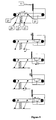
- Figure 7. Displacement of the double conveyor belt with the help of a projection in the belt of the double conveyor belt
- Figure 8. The double conveyor belt with a parallelogram
mechanism
- 1. The tray
- 2. The widened part of the tray
- 3. The plastic cover of the tray
- 4. The belt of the double conveyor belt
- 5. The support for the belt of the double conveyor belt
- 6. The opening
- 7. The motor
- 8. The shaft of the double conveyor belt
- 9. The food heater
- 10. The rotating support
- 11. The mobile part of the hatch of the food heater
- 12. The immobile part of the hatch of the food heater
- 13. The electromagnet
- 14. The moving needle
- 15. The plate made of magnetic material
- 16. The spring for the needle
- 17. The spring for the chain
- 18. The projection in the belt of the double conveyor belt
- 19. The immobile part of the projection response
- 20. The horizontal axis of rotation of the double conveyor belt
- 21. The parallelogram mechanism
-
- Example 1. The
food heater 9 is created in the form of an oven which has arotating support 10. The double conveyor belt is driven by acylindrical shaft 8 connected to themotor 7. The double conveyor belt has a horizontalrotating shaft 20. Theshaft 8 of the double conveyor belt is connected by aspring 17 to a fixed base. In the lower part of the belt of the double conveyor belt there is aprojection 18 positioned with the possibility of interacting with theimmobile response part 19. The projection and the response part are located in such a way that after displacement of the tray within the oven the projection starts to interact with the response part. This leads to the turning of the double conveyor belt around itshorizontal shaft 20. The movement of the belt of the double conveyor belt ends at the moment when the tray starts to rest on the rotating support, and between the widened part of the tray and the belt of the double conveyor belt a previously defined gap is created. After completing the heating of the tray the belt of the double conveyor belt starts to move in the opposite direction, theprojection 18 ceases to interact with theresponse part 19, the conveyor belt returns to the initial position (defined by the corresponding support) under the action of the spring, the tray ceases to interact with the rotating support and rests on the individual belts of the conveyor belt which displace it to the initial position. - Example 2. The
food heater 9 is created in the form of a microwave oven which has arotating support 10. The double conveyor belt is driven by a combinedshaft 8 connected to themotor 7. The double conveyor belt has aparallelogram mechanism 21 for the vertical movement of the conveyor belt and it has aspring 17 connected to a base. Thetray 1 is displaced to the double conveyor belt from the initial position of the store with the help of traditional methods. In the initial position, the device for perforating the covers of the trays performs the perforation of the cover of the tray. After that, the double conveyor belt displaces the tray within the food heater as far as the corresponding position defined by a special support (the rear part of theopening 6 of thesupport 5 of the double conveyor belt can be used as such a support). The mobile part of thehatch 11 is at that moment in the raised position. The mobile part of the hatch is lowered with the help of a special actuator in such a way that it starts to press on the double conveyor belt and lower it down to the position determined by the support when the tray is resting on the rotating support, and a previously defined gap is created between the widened part of the tray and the belts of the chain. The food heater switches on and the rotating support starts to move. When the heating is completed, the heater disconnects and the rotating support stops turning. The mobile part of thehatch 11 opens. In the meantime, the double conveyor belt rises up to the initial position defined by the support. The tray is withdrawn from the heater with the help of the double conveyor belt and the movement of the belts of the double conveyor belt is halted only after the tray is completely withdrawn from the belt of the double conveyor belt in the corresponding container.
Claims (8)
- Automatic food-heating device containing a body which houses a store for food with individual containers, a food heater, a window for delivery of food and a transport system for the individual conveyance of food containers from the store to the heater, and from the heater to the delivery window, characterized in that the heater has a rotating support for the food container, the transport system contains a double conveyor belt, whose individual belts are synchronised and arranged in parallel at a distance less than the minimum horizontal size of the container, but greater than the horizontal size of the rotating support for food in the heater, the individual conveyor belts are arranged symmetrically in relation to the axis of rotation of the rotating support, the double conveyor belt can move in the vertical direction, being limited in its upper part in such a way that the lower part of the container placed on the double conveyor belt is located higher than the upper part of the rotating support for food, and limited in its lower part in such a way that the container rests on the rotating support and does not touch the conveyor belt.
- The device according to claim 1, characterized in that the double conveyor belt can rotate around a horizontal shaft located outside the heater and orientated perpendicularly to the movement of the belt.
- The device according to claims 1 or 2, characterized in that the conveyor belt has a spring and a limit element, highlighted is the fact that in the absence of exterior actions the double conveyor belt rotates around the horizontal axis as far as the limit element, due to the influence of the spring.
- The device according to claims 1-3, characterized in that at least one of the individual belts of the conveyor belt includes a projection with the possibility of interaction with the response part, located in the base.
- The device according to claims 1,2, characterized in that the heater has a hatch located with the possibility of moving in the vertical direction and interacting with the double conveyor belt; the closed position of the hatch corresponds to the lowest position of the double conveyor belt.
- The device according to claims 1-5, characterized in that the transport system contains a device for carrying out perforation of the wrapping material for the food.
- A method of control of an automatic food-heating device consisting of the food being conserved in the store and being conveyed by the conveyor belt to the heater, it is heated and, with the help of the double conveyor belt, is transported to the delivery window which is differentiated in that, following the transfer of the food container to the heater, the double conveyor belt is lowered to the point at which the container comes into contact with the rotating support and ceases to interact with the double conveyor belt, the rotation of the food container is done with the help of the rotating support during the heating, at the end of the heating the food support stops rotating and the double conveyor belt is then raised up to the upper position until the food container rests on the double conveyor belt and the food container does not touch the rotating support, the food container is then conveyed to the delivery window.
- The method according to claim 7, characterized in that prior to heating the food container, the wrapping material for the food is perforated at one or several points.
Applications Claiming Priority (3)
| Application Number | Priority Date | Filing Date | Title |
|---|---|---|---|
| ES200201198A ES2223225B1 (en) | 2002-05-24 | 2002-05-24 | APPARATUS FOR AUTOMATIC HEATING OF EDIBLES. |
| ES200201198 | 2002-05-24 | ||
| PCT/ES2003/000245 WO2003099085A1 (en) | 2002-05-24 | 2003-05-23 | Automatic food-heating device |
Publications (1)
| Publication Number | Publication Date |
|---|---|
| EP1514501A1 true EP1514501A1 (en) | 2005-03-16 |
Family
ID=29558511
Family Applications (1)
| Application Number | Title | Priority Date | Filing Date |
|---|---|---|---|
| EP03725224A Withdrawn EP1514501A1 (en) | 2002-05-24 | 2003-05-23 | Automatic food-heating device |
Country Status (4)
| Country | Link |
|---|---|
| EP (1) | EP1514501A1 (en) |
| AU (1) | AU2003227777A1 (en) |
| ES (1) | ES2223225B1 (en) |
| WO (1) | WO2003099085A1 (en) |
Families Citing this family (1)
| Publication number | Priority date | Publication date | Assignee | Title |
|---|---|---|---|---|
| CN113545654B (en) * | 2021-08-17 | 2022-08-09 | 江南大学 | Cooking equipment for fresh food noodles |
Family Cites Families (4)
| Publication number | Priority date | Publication date | Assignee | Title |
|---|---|---|---|---|
| US3570391A (en) * | 1967-06-27 | 1971-03-16 | Rejlers Ingenjoersbyra Ab | Electronic or microwave furnace or oven |
| US3974353A (en) * | 1973-05-18 | 1976-08-10 | Teckton, Inc. | Conveyorized microwave oven |
| DE2503641A1 (en) * | 1974-02-01 | 1975-08-14 | Dca Food Ind | MICROWAVE SYSTEM AND ASSOCIATED CONTROL UNIT |
| US6201218B1 (en) * | 1998-10-08 | 2001-03-13 | The Frymaster Corporation | Food cooking apparatus with removable conveyor assembly and serpentine heater providing non-uniform heating |
-
2002
- 2002-05-24 ES ES200201198A patent/ES2223225B1/en not_active Expired - Fee Related
-
2003
- 2003-05-23 AU AU2003227777A patent/AU2003227777A1/en not_active Abandoned
- 2003-05-23 WO PCT/ES2003/000245 patent/WO2003099085A1/en not_active Ceased
- 2003-05-23 EP EP03725224A patent/EP1514501A1/en not_active Withdrawn
Non-Patent Citations (1)
| Title |
|---|
| See references of WO03099085A1 * |
Also Published As
| Publication number | Publication date |
|---|---|
| ES2223225B1 (en) | 2006-04-16 |
| ES2223225A1 (en) | 2005-02-16 |
| WO2003099085A1 (en) | 2003-12-04 |
| AU2003227777A1 (en) | 2003-12-12 |
Similar Documents
| Publication | Publication Date | Title |
|---|---|---|
| US3870193A (en) | Apparatus for heating and dispensing french fried potatoes | |
| US5144879A (en) | Automatic food dispenser | |
| EP0591510A1 (en) | An apparatus for dry-cooking food products | |
| CN110801147A (en) | Intelligence spiral shell powder culinary art robot | |
| KR102005480B1 (en) | Microwave cooker of vending machine of instant ramen | |
| JPH067127A (en) | Automatic cooker for hamburger | |
| US20190320846A1 (en) | Horizontal griddle with automatic dispensing | |
| KR101990686B1 (en) | Ramen and pizza complex vending system | |
| US5537915A (en) | Foodstuff dispensing machine | |
| US2838897A (en) | Wrapping machine | |
| JP2004508618A (en) | Dispenser for heated food | |
| Akinfiev et al. | Automatic food-heating device | |
| CN107886624B (en) | Automatic heating system and method and automatic vending machine | |
| US3872783A (en) | Frying apparatus | |
| KR100622782B1 (en) | Steam discharge device of pressure cooker | |
| CN111802414B (en) | Intelligent pancake cracker making and selling machine | |
| EP0792235A1 (en) | Method and apparatus for wrapping spherical objects | |
| KR200274281Y1 (en) | Automatic cooking machine | |
| CN119637218B (en) | A smart food cooking and serving machine | |
| JPH07334753A (en) | Automatic vending machine having incorporated microwave oven | |
| CN109516168B (en) | A dining table mechanism and automated kitchen system | |
| KR20230001868A (en) | vending machine for ramen | |
| WO2003099085A1 (en) | Automatic food-heating device | |
| US3853620A (en) | Method for automatically opening and emptying containers into a blending tank | |
| JPH0237491A (en) | Automatic vending machine for food exclusive for microwave oven |
Legal Events
| Date | Code | Title | Description |
|---|---|---|---|
| PUAI | Public reference made under article 153(3) epc to a published international application that has entered the european phase |
Free format text: ORIGINAL CODE: 0009012 |
|
| 17P | Request for examination filed |
Effective date: 20041220 |
|
| AK | Designated contracting states |
Kind code of ref document: A1 Designated state(s): AT BE BG CH CY CZ DE DK EE ES FI FR GB GR HU IE IT LI LU MC NL PT RO SE SI SK TR |
|
| AX | Request for extension of the european patent |
Extension state: AL LT LV MK |
|
| GRAP | Despatch of communication of intention to grant a patent |
Free format text: ORIGINAL CODE: EPIDOSNIGR1 |
|
| DAX | Request for extension of the european patent (deleted) | ||
| STAA | Information on the status of an ep patent application or granted ep patent |
Free format text: STATUS: THE APPLICATION IS DEEMED TO BE WITHDRAWN |
|
| 18D | Application deemed to be withdrawn |
Effective date: 20051025 |